EP1162633A1 - Verfahren zur Herstellung von Drilleitern - Google Patents
Verfahren zur Herstellung von Drilleitern Download PDFInfo
- Publication number
- EP1162633A1 EP1162633A1 EP01401153A EP01401153A EP1162633A1 EP 1162633 A1 EP1162633 A1 EP 1162633A1 EP 01401153 A EP01401153 A EP 01401153A EP 01401153 A EP01401153 A EP 01401153A EP 1162633 A1 EP1162633 A1 EP 1162633A1
- Authority
- EP
- European Patent Office
- Prior art keywords
- stack
- tool
- profile
- conductors
- spindle
- Prior art date
- Legal status (The legal status is an assumption and is not a legal conclusion. Google has not performed a legal analysis and makes no representation as to the accuracy of the status listed.)
- Granted
Links
Images
Classifications
-
- H—ELECTRICITY
- H02—GENERATION; CONVERSION OR DISTRIBUTION OF ELECTRIC POWER
- H02K—DYNAMO-ELECTRIC MACHINES
- H02K15/00—Processes or apparatus specially adapted for manufacturing, assembling, maintaining or repairing of dynamo-electric machines
- H02K15/04—Processes or apparatus specially adapted for manufacturing, assembling, maintaining or repairing of dynamo-electric machines of windings prior to their mounting into the machines
- H02K15/0414—Processes or apparatus specially adapted for manufacturing, assembling, maintaining or repairing of dynamo-electric machines of windings prior to their mounting into the machines the windings consisting of separate elements, e.g. bars, segments or half coils
-
- H—ELECTRICITY
- H01—ELECTRIC ELEMENTS
- H01B—CABLES; CONDUCTORS; INSULATORS; SELECTION OF MATERIALS FOR THEIR CONDUCTIVE, INSULATING OR DIELECTRIC PROPERTIES
- H01B13/00—Apparatus or processes specially adapted for manufacturing conductors or cables
- H01B13/02—Stranding-up
- H01B13/0278—Stranding machines comprising a transposing mechanism
-
- H—ELECTRICITY
- H02—GENERATION; CONVERSION OR DISTRIBUTION OF ELECTRIC POWER
- H02K—DYNAMO-ELECTRIC MACHINES
- H02K3/00—Details of windings
- H02K3/04—Windings characterised by the conductor shape, form or construction, e.g. with bar conductors
- H02K3/12—Windings characterised by the conductor shape, form or construction, e.g. with bar conductors arranged in slots
- H02K3/14—Windings characterised by the conductor shape, form or construction, e.g. with bar conductors arranged in slots with transposed conductors, e.g. twisted conductors
-
- Y—GENERAL TAGGING OF NEW TECHNOLOGICAL DEVELOPMENTS; GENERAL TAGGING OF CROSS-SECTIONAL TECHNOLOGIES SPANNING OVER SEVERAL SECTIONS OF THE IPC; TECHNICAL SUBJECTS COVERED BY FORMER USPC CROSS-REFERENCE ART COLLECTIONS [XRACs] AND DIGESTS
- Y10—TECHNICAL SUBJECTS COVERED BY FORMER USPC
- Y10T—TECHNICAL SUBJECTS COVERED BY FORMER US CLASSIFICATION
- Y10T29/00—Metal working
- Y10T29/49—Method of mechanical manufacture
- Y10T29/49002—Electrical device making
- Y10T29/49117—Conductor or circuit manufacturing
Definitions
- the invention relates to a method for producing twisted pairs according to the preamble of claim 1 and a device for producing twisted conductors according to Preamble of claim 5.
- GB-PS 969 086 is a device for producing a composite known electrical conductor, in which the isolated individual conductors of rectangular Cross-section in parallel stacks of a rocking tool run through. On the circumference of the strand formed from the stacked profile wires attack sliders, which on the lowest or uppermost profile conductor move the adjacent stack by cranking it. This process, the The twisting of angular profile conductors is called Röbel after the inventor Rub it, and the tool is called a rocking tool.
- the Röbelwerkmaschine In addition to the two sliders for moving the upper and lower profile wire the Röbelwerkmaschine also has two pushers in the adjacent stack, each of which push a stack of single conductors up or down. After completion this pushing process, the sliders engage to move the profile wires in the described way.
- crank length is the length from the beginning to at the end of a bend, relatively large. This will make the wrap property deteriorated especially in the case of stranded conductors with a large number of profiled wires.
- the tool elements are actuated by cams and eccentrics Synchronization takes place through a ring gear.
- crank length and thus the step and lay length of the wire conductor should be as short as possible keep and thus improve its windability, is from DE-A-39 23 448 Appeared device in which each slide a counter-holder on the opposite side of the conductor is assigned, which in the conveying direction of the Drilleiters offset to the slide and opposite to this across the drill conductor is slidably mounted and synchronized with the movement of the slide and pushers is driven.
- Slides, counterholders and pushers are operated by hydraulic or pneumatic actuators electronically controlled set in motion.
- the present invention has for its object to show a way with which the cycle time of the tools and thus the production speed can be increased.
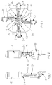
- FIGS. 1 to 3 Exemplary embodiments explained in more detail.
- FIG. 1 shows a view of a Röbelkopf in the production direction of the Röbelstab or Drilleiters 1.
- the twisted pair 1 consists of a plurality of sub-conductors 1 a, which in two Stack 1b and 1c are divided.
- the stack 1c is followed by for raking the partial conductor 1a moved up and the stack 1b down.
- FIG lowest partial conductor 1a of the stack 1b on the stack 1c and the uppermost partial conductor 1a of the Stack 1c moved to stack 1b.
- This method is known, it can either with an even or with an odd number of partial conductors 1a be performed.
- the stacks 1b and 1c are driven by the servomotors 2 and 3 postponed. Moving the partial conductors 1a onto the adjacent stacks 1b and 1c is done by the servomotors 4 and 5. By a short offset length of the partial conductor 1a To achieve, two further servomotors 6 and 7 are provided, which Counteract servomotors 4 and 5.
- Each of the servomotors 2 to 7 drives on the as described in more detail below Drill conductor 1 acting tool 8 to 13.
- the rotor 14 of the servo motor 2 is connected to a spindle 15 and drives it their longitudinal axis.
- the spindle 15 has a helical shape running groove or elevation or a helical thread.
- the tool 8 has an unspecified bore, the inner one Surface is adapted to the course of the groove or the thread.
- the tool 8 is guided in a guide 16 and thus secured against twisting.
- spindle 15 becomes a rotary movement into a translatory movement converted, d. H. the tool 8 is depending on the direction of rotation from or to the Cable ladder 1 moves.
Landscapes
- Engineering & Computer Science (AREA)
- Manufacturing & Machinery (AREA)
- Power Engineering (AREA)
- Processes Specially Adapted For Manufacturing Cables (AREA)
- Manufacture Of Motors, Generators (AREA)
- Ropes Or Cables (AREA)
- Wire Processing (AREA)
Abstract
Description
Claims (8)
- Verfahren zur Herstellung von Drilleitern durch Verröbeln von Profildrähten mit rechteckigem Querschnitt mit einer Führung für die in zwei parallelen Stapeln geförderten Profildrähte, bei welchem der jeweils zuunterst und zuoberst liegende Profilleiter auf den benachbarten Stapel unter Kröpfung desselben verschoben wird und der eine Stapel nach oben und der andere Stapel nach unten gedrückt wird, dadurch gekennzeichnet, daß das Verschieben der Profilleiter und das Drücken der Stapel durch Servomotoren erfolgt.
- Verfahren nach Anspruch 1, dadurch gekennzeichnet, daß jeder der Servomotoren jeweils eine Spindel antreibt.
- Verfahren nach Anspruch 2, dadurch gekennzeichnet, daß als Spindeln Kugelrollspindeln verwendet werden, welche die Drehbewegung der Servomotoren in translatorische Bewegungen umwandeln.
- Verfahren nach einem der Ansprüche 1 bis 3, dadurch gekennzeichnet, daß jeder Servomotor rechnergesteuert wird.
- Vorrichtung zur Herstellung von Drilleitern durch Verröbeln von Profildrähten mit rechteckigem Querschnitt, mit einer Führung für die in zwei parallelen Stapeln geförderten Profildrähte, in welcher der jeweils zuunterst und der zuoberst liegende Profilleiter auf den benachbarten Stapel unter Kröpfung desselben durch Werkzeuge verschoben wird und der eine Stapel nach oben und der andere Stapel nach unten ebenfalls durch Werkzeuge gedrückt wird, dadurch gekennzeichnet, daß jeweils ein Servomotor (2 bis 7) zum Antrieb für ein Werkzeug (8 bis 13) vorgesehen ist.
- Vorrichtung nach Anspruch 5, dadurch gekennzeichnet, daß der Rotor (14) jedes Servomotors (2 bis 7) mit einer Spindel (15) verbunden ist, daß jedes Werkzeug (8 bis 13) eine Bohrung aufweist, deren Oberfläche einen der Spindel (15) angepaßten Gewindegang aufweist und daß jedes Werkzeug (8 bis 13) in einer Führung (16) geführt ist.
- Vorrichtung nach Anspruch 6, dadurch gekennzeichnet, daß jedes Werkzeug (8 bis 13) eine Kugelrollspindel (15) aufweist.
- Vorrichtung nach einem der Ansprüche 5 bis 7, dadurch gekennzeichnet, daß ein Rechner vorgesehen ist, der den Antrieb der Servomotoren (2 bis 7) in Abhängigkeit von den Parametern für die Drilleiter (1) steuert.
Applications Claiming Priority (2)
| Application Number | Priority Date | Filing Date | Title |
|---|---|---|---|
| DE10027564A DE10027564A1 (de) | 2000-06-02 | 2000-06-02 | Verfahren zur Herstellung von Drilleitern |
| DE10027564 | 2000-06-02 |
Publications (2)
| Publication Number | Publication Date |
|---|---|
| EP1162633A1 true EP1162633A1 (de) | 2001-12-12 |
| EP1162633B1 EP1162633B1 (de) | 2005-07-20 |
Family
ID=7644593
Family Applications (1)
| Application Number | Title | Priority Date | Filing Date |
|---|---|---|---|
| EP01401153A Expired - Lifetime EP1162633B1 (de) | 2000-06-02 | 2001-05-04 | Verfahren und Vorrichtung zur Herstellung von Drilleitern |
Country Status (6)
| Country | Link |
|---|---|
| US (1) | US20020050057A1 (de) |
| EP (1) | EP1162633B1 (de) |
| JP (1) | JP2002042590A (de) |
| CN (1) | CN1189265C (de) |
| AT (1) | ATE300089T1 (de) |
| DE (2) | DE10027564A1 (de) |
Families Citing this family (13)
| Publication number | Priority date | Publication date | Assignee | Title |
|---|---|---|---|---|
| WO2005096322A1 (en) * | 2004-03-31 | 2005-10-13 | Industrial Research Limited | Composite superconductor cable produced by transposing planar subconductors |
| US7788893B2 (en) * | 2006-12-21 | 2010-09-07 | General Cable Superconductors Limited | Apparatus and method for producing composite cable |
| US8156637B2 (en) | 2006-12-21 | 2012-04-17 | General Cable Superconductors Limited | Apparatus for forming HTS continuous conductor elements |
| US7980051B2 (en) * | 2006-12-21 | 2011-07-19 | General Cable Superconductors Limited | Apparatus and method for producing composite cable |
| AT508621A1 (de) | 2009-07-22 | 2011-02-15 | Asta Elektrodraht Gmbh | Kontinuierlicher drillleiter |
| CN101913140B (zh) * | 2010-06-28 | 2011-11-16 | 河南省电力公司周口供电公司 | 输配电线路砼杆钢绞线制作平台 |
| CN104057000B (zh) * | 2014-06-23 | 2017-12-08 | 国家电网公司 | 母线扭弯工装 |
| KR101604840B1 (ko) * | 2015-11-17 | 2016-03-21 | (주)삼동 | 다수의 라이너 액츄에이터를 사용하는 연속전위권선 제조장치 및 제조방법 |
| CN107262634B (zh) * | 2017-08-04 | 2018-12-28 | 泉州台商投资区点优网络科技有限公司 | 一种电缆线自动扭转设备 |
| WO2019071187A1 (en) | 2017-10-06 | 2019-04-11 | Cargill, Incorporated | STABILIZED GLYCOSIDE COMPOSITIONS OF STEVIOL AND USES THEREOF |
| AU2020273144B2 (en) | 2019-04-06 | 2025-07-03 | Cargill, Incorporated | Methods for making botanical extract composition |
| CN110504071B (zh) * | 2019-08-28 | 2020-11-10 | 义乌市凡特塑料制品有限公司 | 一种可调节线束扭线装置 |
| CN116099954A (zh) * | 2022-12-16 | 2023-05-12 | 杭州电力设备制造有限公司 | 一种错线检测与折线装置 |
Citations (2)
| Publication number | Priority date | Publication date | Assignee | Title |
|---|---|---|---|---|
| WO1997032316A1 (en) * | 1996-02-28 | 1997-09-04 | Proteco Di Cappa Rasone Edda & C. S.A.S. | Transposing apparatus for the manufacture of c.t.c. conductors |
| JP2000069722A (ja) * | 1998-08-26 | 2000-03-03 | Fuji Electric Co Ltd | 回転電気機械の転位コイル用の製造装置および回転電気機械用の転位コイルの製造方法 |
Family Cites Families (4)
| Publication number | Priority date | Publication date | Assignee | Title |
|---|---|---|---|---|
| US3154112A (en) * | 1961-11-15 | 1964-10-27 | Gen Electric | Strand transposing mechanism |
| DE3923448A1 (de) * | 1989-07-15 | 1991-01-24 | Lackdraht Union Gmbh | Vorrichtung zum erzeugen von drilleitern |
| IT1247920B (it) * | 1991-05-13 | 1995-01-05 | Pirelli Cavi S P A Dir Proprie | Testa di estrusione per applicare rivestimenti in materiale polimerico su semilavorati di conformazione cilindrica allungata |
| DE19816189C2 (de) * | 1998-04-14 | 2000-03-09 | Kuehne & Vogel Gmbh | SZ-Verseilmaschine mit Einzelantrieben |
-
2000
- 2000-06-02 DE DE10027564A patent/DE10027564A1/de not_active Withdrawn
-
2001
- 2001-05-04 EP EP01401153A patent/EP1162633B1/de not_active Expired - Lifetime
- 2001-05-04 DE DE50106763T patent/DE50106763D1/de not_active Expired - Lifetime
- 2001-05-04 AT AT01401153T patent/ATE300089T1/de active
- 2001-05-29 CN CNB011208155A patent/CN1189265C/zh not_active Expired - Fee Related
- 2001-06-01 US US09/870,787 patent/US20020050057A1/en not_active Abandoned
- 2001-06-01 JP JP2001167235A patent/JP2002042590A/ja active Pending
Patent Citations (2)
| Publication number | Priority date | Publication date | Assignee | Title |
|---|---|---|---|---|
| WO1997032316A1 (en) * | 1996-02-28 | 1997-09-04 | Proteco Di Cappa Rasone Edda & C. S.A.S. | Transposing apparatus for the manufacture of c.t.c. conductors |
| JP2000069722A (ja) * | 1998-08-26 | 2000-03-03 | Fuji Electric Co Ltd | 回転電気機械の転位コイル用の製造装置および回転電気機械用の転位コイルの製造方法 |
Non-Patent Citations (1)
| Title |
|---|
| PATENT ABSTRACTS OF JAPAN vol. 2000, no. 06 22 September 2000 (2000-09-22) * |
Also Published As
| Publication number | Publication date |
|---|---|
| EP1162633B1 (de) | 2005-07-20 |
| US20020050057A1 (en) | 2002-05-02 |
| JP2002042590A (ja) | 2002-02-08 |
| DE50106763D1 (de) | 2005-08-25 |
| ATE300089T1 (de) | 2005-08-15 |
| CN1189265C (zh) | 2005-02-16 |
| DE10027564A1 (de) | 2001-12-06 |
| CN1326827A (zh) | 2001-12-19 |
Similar Documents
| Publication | Publication Date | Title |
|---|---|---|
| EP3381108B1 (de) | Verfahren zur herstellung einer spulenwicklung zum einlegen in radial offene nuten von statoren oder rotoren von elektromaschinen | |
| EP0968563B1 (de) | Verfahren und vorrichtung zum herstellen von wellenwicklungen für elektrische maschinen | |
| DE112016000469T5 (de) | Stator-herstellungs-gerät und stator-herstellungs-verfahren | |
| DE102010004781B4 (de) | Trenn- und Abisoliereinrichtung für eine Kabelverarbeitungsmaschine | |
| EP1162633B1 (de) | Verfahren und Vorrichtung zur Herstellung von Drilleitern | |
| WO2005002027A2 (de) | Verfahren und vorrichtung zum einführen von wellenwicklungen in rotor- und statorblechpakete elektrischer maschinen | |
| WO2017153502A1 (de) | Herstellungsverfahren für einen stator | |
| AT520311B1 (de) | Verfahren und Vorrichtung zur automatisierten Herstellung eines Stators einer elektrischen Maschine | |
| DE2001677A1 (de) | Wicklungsvorrichtung fuer die Staendernuten elektrischer Maschinen | |
| DE102014226224A1 (de) | Verfahren zum Formen zumindest eines U-förmigen Wickelelements für einen elektromagnetisch erregbaren Kern einer elektrischen Rotationsmaschine | |
| DE102017114021B4 (de) | Vorrichtung und Verfahren zum Bearbeiten mindestens eines Leitersegments eines Wicklungsträgers einer elektrischen Maschine | |
| EP2522451A1 (de) | Verfahren zum Ausformen eines Innengewindes sowie Kombination aus einem Grundkörper mit einer Ausnehmung und einem Gewindeschneider | |
| DE102019117966A1 (de) | Verfahren zur Herstellung einer Spulenwicklung zum Einlegen in radial offene Nuten von Statoren oder Rotoren von Elektromaschinen | |
| CH621020A5 (de) | ||
| DE102018106980A1 (de) | Vorrichtung und Verfahren zum Biegen von Draht für die Herstellung von Maschinenelementen elektrischer Maschinen | |
| EP3771078A1 (de) | Kranzanordnungs- und -fügevorrichtung sowie kranzanordnungs- und -fügeverfahren | |
| EP0222140B1 (de) | Verfahren und Vorrichtung zum Biegen einer Anzahl von nebeneinander und/oder übereinander liegenden, elektrisch isolierten stabförmigen Leitern | |
| AT520356A1 (de) | Verfahren und Vorrichtung zur automatisierten Herstellung einer Komponente eines Stators oder Rotors einer elektrischen Maschine | |
| EP1552593A1 (de) | Wickelmaschine sowie verfahren zur herstellung einer wicklung | |
| DE102014003602A1 (de) | Verfahren zum Herstellen einer Wicklung | |
| DE19817304B4 (de) | Verfahren und Vorrichtung zum Herstellen von Wellenwicklungen für elektrische Maschinen | |
| EP4175139B1 (de) | Vorrichtung und verfahren zum herstellen einer biegung einer wellenwicklung für eine spulenwicklung einer elektrischen maschine | |
| EP0408832B1 (de) | Vorrichtung zum Erzeugen von Drilleitern | |
| DE3343390C2 (de) | Verfahren zum Herstellen von Wellenwicklungen und Vorrichtung zum Durchführen dieses Verfahrens | |
| EP2269285A2 (de) | Verfahren und vorrichtung zur herstellung einer elektrischen wicklung |
Legal Events
| Date | Code | Title | Description |
|---|---|---|---|
| PUAI | Public reference made under article 153(3) epc to a published international application that has entered the european phase |
Free format text: ORIGINAL CODE: 0009012 |
|
| AK | Designated contracting states |
Kind code of ref document: A1 Designated state(s): AT BE CH CY DE DK ES FI FR GB GR IE IT LI LU MC NL PT SE TR |
|
| AX | Request for extension of the european patent |
Free format text: AL;LT;LV;MK;RO;SI |
|
| 17P | Request for examination filed |
Effective date: 20020111 |
|
| AKX | Designation fees paid |
Free format text: AT BE CH CY DE DK ES FI FR GB GR IE IT LI LU MC NL PT SE TR |
|
| 17Q | First examination report despatched |
Effective date: 20040701 |
|
| GRAP | Despatch of communication of intention to grant a patent |
Free format text: ORIGINAL CODE: EPIDOSNIGR1 |
|
| RTI1 | Title (correction) |
Free format text: MANUFACTURING METHOD AND APPARATUS FOR TRANSPOSED CONDUCTORS |
|
| GRAS | Grant fee paid |
Free format text: ORIGINAL CODE: EPIDOSNIGR3 |
|
| GRAA | (expected) grant |
Free format text: ORIGINAL CODE: 0009210 |
|
| AK | Designated contracting states |
Kind code of ref document: B1 Designated state(s): AT BE CH CY DE DK ES FI FR GB GR IE IT LI LU MC NL PT SE TR |
|
| PG25 | Lapsed in a contracting state [announced via postgrant information from national office to epo] |
Ref country code: FI Free format text: LAPSE BECAUSE OF FAILURE TO SUBMIT A TRANSLATION OF THE DESCRIPTION OR TO PAY THE FEE WITHIN THE PRESCRIBED TIME-LIMIT Effective date: 20050720 Ref country code: TR Free format text: LAPSE BECAUSE OF FAILURE TO SUBMIT A TRANSLATION OF THE DESCRIPTION OR TO PAY THE FEE WITHIN THE PRESCRIBED TIME-LIMIT Effective date: 20050720 Ref country code: NL Free format text: LAPSE BECAUSE OF FAILURE TO SUBMIT A TRANSLATION OF THE DESCRIPTION OR TO PAY THE FEE WITHIN THE PRESCRIBED TIME-LIMIT Effective date: 20050720 Ref country code: IE Free format text: LAPSE BECAUSE OF FAILURE TO SUBMIT A TRANSLATION OF THE DESCRIPTION OR TO PAY THE FEE WITHIN THE PRESCRIBED TIME-LIMIT Effective date: 20050720 |
|
| REG | Reference to a national code |
Ref country code: GB Ref legal event code: FG4D Free format text: NOT ENGLISH |
|
| REG | Reference to a national code |
Ref country code: CH Ref legal event code: EP |
|
| GBT | Gb: translation of ep patent filed (gb section 77(6)(a)/1977) |
Effective date: 20050720 |
|
| REG | Reference to a national code |
Ref country code: IE Ref legal event code: FG4D Free format text: LANGUAGE OF EP DOCUMENT: GERMAN |
|
| REF | Corresponds to: |
Ref document number: 50106763 Country of ref document: DE Date of ref document: 20050825 Kind code of ref document: P |
|
| PG25 | Lapsed in a contracting state [announced via postgrant information from national office to epo] |
Ref country code: DK Free format text: LAPSE BECAUSE OF FAILURE TO SUBMIT A TRANSLATION OF THE DESCRIPTION OR TO PAY THE FEE WITHIN THE PRESCRIBED TIME-LIMIT Effective date: 20051020 Ref country code: GR Free format text: LAPSE BECAUSE OF FAILURE TO SUBMIT A TRANSLATION OF THE DESCRIPTION OR TO PAY THE FEE WITHIN THE PRESCRIBED TIME-LIMIT Effective date: 20051020 Ref country code: SE Free format text: LAPSE BECAUSE OF FAILURE TO SUBMIT A TRANSLATION OF THE DESCRIPTION OR TO PAY THE FEE WITHIN THE PRESCRIBED TIME-LIMIT Effective date: 20051020 |
|
| PG25 | Lapsed in a contracting state [announced via postgrant information from national office to epo] |
Ref country code: ES Free format text: LAPSE BECAUSE OF FAILURE TO SUBMIT A TRANSLATION OF THE DESCRIPTION OR TO PAY THE FEE WITHIN THE PRESCRIBED TIME-LIMIT Effective date: 20051031 |
|
| PG25 | Lapsed in a contracting state [announced via postgrant information from national office to epo] |
Ref country code: PT Free format text: LAPSE BECAUSE OF FAILURE TO SUBMIT A TRANSLATION OF THE DESCRIPTION OR TO PAY THE FEE WITHIN THE PRESCRIBED TIME-LIMIT Effective date: 20051221 |
|
| NLV1 | Nl: lapsed or annulled due to failure to fulfill the requirements of art. 29p and 29m of the patents act | ||
| REG | Reference to a national code |
Ref country code: IE Ref legal event code: FD4D |
|
| PGFP | Annual fee paid to national office [announced via postgrant information from national office to epo] |
Ref country code: MC Payment date: 20060426 Year of fee payment: 6 |
|
| PGFP | Annual fee paid to national office [announced via postgrant information from national office to epo] |
Ref country code: CH Payment date: 20060427 Year of fee payment: 6 |
|
| ET | Fr: translation filed | ||
| PLBE | No opposition filed within time limit |
Free format text: ORIGINAL CODE: 0009261 |
|
| STAA | Information on the status of an ep patent application or granted ep patent |
Free format text: STATUS: NO OPPOSITION FILED WITHIN TIME LIMIT |
|
| PGFP | Annual fee paid to national office [announced via postgrant information from national office to epo] |
Ref country code: LU Payment date: 20060607 Year of fee payment: 6 |
|
| 26N | No opposition filed |
Effective date: 20060421 |
|
| PGFP | Annual fee paid to national office [announced via postgrant information from national office to epo] |
Ref country code: BE Payment date: 20060712 Year of fee payment: 6 |
|
| REG | Reference to a national code |
Ref country code: GB Ref legal event code: 732E |
|
| REG | Reference to a national code |
Ref country code: FR Ref legal event code: TP |
|
| BERE | Be: lapsed |
Owner name: NEXANS Effective date: 20070531 |
|
| REG | Reference to a national code |
Ref country code: CH Ref legal event code: PL |
|
| PG25 | Lapsed in a contracting state [announced via postgrant information from national office to epo] |
Ref country code: MC Free format text: LAPSE BECAUSE OF NON-PAYMENT OF DUE FEES Effective date: 20070531 |
|
| PG25 | Lapsed in a contracting state [announced via postgrant information from national office to epo] |
Ref country code: LI Free format text: LAPSE BECAUSE OF NON-PAYMENT OF DUE FEES Effective date: 20070531 Ref country code: CH Free format text: LAPSE BECAUSE OF NON-PAYMENT OF DUE FEES Effective date: 20070531 |
|
| PG25 | Lapsed in a contracting state [announced via postgrant information from national office to epo] |
Ref country code: BE Free format text: LAPSE BECAUSE OF NON-PAYMENT OF DUE FEES Effective date: 20070531 |
|
| REG | Reference to a national code |
Ref country code: FR Ref legal event code: CD |
|
| PG25 | Lapsed in a contracting state [announced via postgrant information from national office to epo] |
Ref country code: CY Free format text: LAPSE BECAUSE OF FAILURE TO SUBMIT A TRANSLATION OF THE DESCRIPTION OR TO PAY THE FEE WITHIN THE PRESCRIBED TIME-LIMIT Effective date: 20050720 |
|
| PG25 | Lapsed in a contracting state [announced via postgrant information from national office to epo] |
Ref country code: LU Free format text: LAPSE BECAUSE OF NON-PAYMENT OF DUE FEES Effective date: 20070504 |
|
| REG | Reference to a national code |
Ref country code: DE Ref legal event code: R082 Ref document number: 50106763 Country of ref document: DE Representative=s name: , Ref country code: DE Ref legal event code: R082 Ref document number: 50106763 Country of ref document: DE Representative=s name: CBDL PATENTANWAELTE, DE |
|
| REG | Reference to a national code |
Ref country code: FR Ref legal event code: PLFP Year of fee payment: 16 |
|
| REG | Reference to a national code |
Ref country code: FR Ref legal event code: PLFP Year of fee payment: 17 |
|
| PGFP | Annual fee paid to national office [announced via postgrant information from national office to epo] |
Ref country code: DE Payment date: 20170511 Year of fee payment: 17 Ref country code: GB Payment date: 20170517 Year of fee payment: 17 Ref country code: FR Payment date: 20170523 Year of fee payment: 17 |
|
| PGFP | Annual fee paid to national office [announced via postgrant information from national office to epo] |
Ref country code: IT Payment date: 20170517 Year of fee payment: 17 Ref country code: AT Payment date: 20170420 Year of fee payment: 17 |
|
| REG | Reference to a national code |
Ref country code: DE Ref legal event code: R119 Ref document number: 50106763 Country of ref document: DE |
|
| REG | Reference to a national code |
Ref country code: AT Ref legal event code: MM01 Ref document number: 300089 Country of ref document: AT Kind code of ref document: T Effective date: 20180504 |
|
| GBPC | Gb: european patent ceased through non-payment of renewal fee |
Effective date: 20180504 |
|
| PG25 | Lapsed in a contracting state [announced via postgrant information from national office to epo] |
Ref country code: AT Free format text: LAPSE BECAUSE OF NON-PAYMENT OF DUE FEES Effective date: 20180504 |
|
| PG25 | Lapsed in a contracting state [announced via postgrant information from national office to epo] |
Ref country code: FR Free format text: LAPSE BECAUSE OF NON-PAYMENT OF DUE FEES Effective date: 20180531 Ref country code: DE Free format text: LAPSE BECAUSE OF NON-PAYMENT OF DUE FEES Effective date: 20181201 Ref country code: IT Free format text: LAPSE BECAUSE OF NON-PAYMENT OF DUE FEES Effective date: 20180504 Ref country code: GB Free format text: LAPSE BECAUSE OF NON-PAYMENT OF DUE FEES Effective date: 20180504 |