EP1162575B1 - Werkzeug zur dreidimensionalen Analyse einer Zeichnung - Google Patents
Werkzeug zur dreidimensionalen Analyse einer Zeichnung Download PDFInfo
- Publication number
- EP1162575B1 EP1162575B1 EP01401404A EP01401404A EP1162575B1 EP 1162575 B1 EP1162575 B1 EP 1162575B1 EP 01401404 A EP01401404 A EP 01401404A EP 01401404 A EP01401404 A EP 01401404A EP 1162575 B1 EP1162575 B1 EP 1162575B1
- Authority
- EP
- European Patent Office
- Prior art keywords
- edge
- view
- selected edge
- faces
- edges
- Prior art date
- Legal status (The legal status is an assumption and is not a legal conclusion. Google has not performed a legal analysis and makes no representation as to the accuracy of the status listed.)
- Expired - Lifetime
Links
Images


Classifications
-
- G—PHYSICS
- G06—COMPUTING OR CALCULATING; COUNTING
- G06T—IMAGE DATA PROCESSING OR GENERATION, IN GENERAL
- G06T19/00—Manipulating three-dimensional [3D] models or images for computer graphics
-
- G—PHYSICS
- G06—COMPUTING OR CALCULATING; COUNTING
- G06T—IMAGE DATA PROCESSING OR GENERATION, IN GENERAL
- G06T2219/00—Indexing scheme for manipulating 3D models or images for computer graphics
- G06T2219/028—Multiple view windows (top-side-front-sagittal-orthogonal)
-
- G—PHYSICS
- G06—COMPUTING OR CALCULATING; COUNTING
- G06T—IMAGE DATA PROCESSING OR GENERATION, IN GENERAL
- G06T2219/00—Indexing scheme for manipulating 3D models or images for computer graphics
- G06T2219/20—Indexing scheme for editing of 3D models
- G06T2219/2012—Colour editing, changing, or manipulating; Use of colour codes
Definitions
- the present invention relates to computer software utility programs, and more specifically to programs in the field of computer-aided design (CAD), computer aided manufacturing (CAM), and computer aided engineering (CAE). More generally, it relates to the display of multiple views of an object as seen from different positions with respect to the object.
- CAD computer-aided design
- CAM computer aided manufacturing
- CAE computer aided engineering
- parts or objects can be designed using three dimensional modeling software.
- An object designed using such software is composed of a number of faces, each of which has a set of edges.
- the information related to the decomposition of a three dimensional (“3D") solid into faces, edges and vertices, and the logical relationships between these elements, is known as topological information, and is stored in topological journals.
- CAD/CAM/CAE In the field of CAD/CAM/CAE various tools are available to a designer for the purpose of facilitating the design and analysis of an object or part.
- a drawing is created to be sent to a machinist or supplier for the purpose of giving the machinist or supplier the information that is necessary to make the object.
- a drawing can contain various two dimensional projections of a part, such as for example, a top view, a left-side view, a right-side view, a bottom view, etc., and normally contains several different projected, cutting or detailed views of an object.
- These drawings are created so as to comply with various industry standards, such as ISO, JIS, and ANSI, for example, so that all the necessary information is provided to the machinist for making the part.
- the drawing is supplied in electronic format.
- the geometry represented is a wireframe representation of the 3D solid projected into a drawing view, and has no semantic (such as face or edge); it is a collection of line segments.
- the relationships between line segments in a drawing and edges or faces in a 3D solid are established through tables associating each line segment in a view to an edge. Face identification is then performed from edges through the topological journals.
- edges or faces in a drawing view it should be understood that what is referred to is line segments representing these edges or faces.
- Document JP-A-08 147498 describes an element selecting system for three-dimensional model.
- This system is constituted so as to be provided with a model display means which displays the two-dimensional view on a window and displays the three-dimensional view on another window, and an element selecting means which emphasis-displays the edge or plane on the designated two-dimensional view or three-dimensional view in accordance with the designation of the arbitrary edge or plane on the two-dimensional view or three-dimensional view, and simultaneously, emphasis-displays together the corresponding edge or plane on another three-dimensional view or two-dimensional view.
- the present invention provides a system, method, and apparatus for providing a visual tool showing correspondence between views of the same portion of an object in every view of a drawing and for enabling a faster and more accurate comprehension of the geometry of the displayed object by the user.
- a user may select a representation of an edge of an object.
- the edge of the object is automatically highlighted in each of the other views being displayed. In the preferred embodiment, this edge is also highlighted in a window where the object is represented in three dimensions.
- all edges of all faces of the object that adjoin the selected edge are also highlighted, both in the view selected by the user, and in each of the other views.
- the user may select a specific edge of an object in one of the views by moving a cursor over the edge.
- a cursor over the edge.
- it is highlighted in each of the other views being displayed.
- the edges and adjoining faces are highlighted differently so as not to confuse the user.
- the selected edge is highlighted in blue, and faces adjoining the selected edge are distinguished by highlighting each of their edges in red. This provides the user with much needed cross-referencing information between views, thus facilitating comprehension of the drawing.
- the computer 100 has a central processor 101 connected to a processor host bus 102 over which it provides data, address and control signals.
- the processors 101 may be any conventional general-purpose single-chip or multichip microprocessor such as a Pentium® series processor, a K6 processor, a MIPS® processor, a Power PC® processor or an ALPHA® processor.
- the processor 101 may be any conventional special purpose microprocessor such as a digital signal processor or a graphics processor.
- the microprocessor 101 can have conventional address, data, and control lines coupling it to a processor host bus 102.
- the computer 100 can include a system controller 103 having an integrated RAM memory controller 104.
- the system controller 103 can be connected to the host bus 102 and provide an interface to random access memory 105.
- the system controller 103 can also provide host bus to peripheral bus bridging functions.
- the controller 103 can thereby permit signals on the processor host bus 102 to be compatibly exchanged with signals on a primary peripheral bus 110.
- the peripheral bus 110 may be, for example, a Peripheral Component Interconnect (PCI) bus, an Industry Standard Architecture (ISA) bus, or a Micro-Channel bus.
- PCI Peripheral Component Interconnect
- ISA Industry Standard Architecture
- Micro-Channel bus Micro-Channel bus
- the controller 103 can thereby allow, for example, a processor 101 having a 64-bit 66 MHz interface and a 533 Mbytes/second data transfer rate to interface to a PCI bus 110 having a data path differing in data path bit width, clock speed, or data transfer rate.
- Accessory devices including, for example, a hard disk drive control interface 111 coupled to a hard disk drive 113, a video display controller 112 coupled to a video display 115, and a keyboard and mouse controller 121 can be coupled to a bus 120 and controlled by the processor 101.
- the computer system can include a connection to a computer system network, an intranet or an internet. Data and information may be sent and received over such a connection.
- the computer 100 can also include nonvolatile ROM memory 122 to store basic computer software routines.
- ROM 122 may include alterable memory, such as EEPROM (Electronically Erasable Programmable Read Only Memory), to store configuration data.
- BIOS routines 123 can be included in ROM 122 and provide basic computer initialization, systems testing, and input/output (I/O) services.
- the BIOS 123 can also include routines that allow an operating system to be "booted" from the disk 113. Examples of high-level operating systems are, the Microsoft Windows 98TM, Windows NTTM, UNIX, LINUX, the Apple MacOSTM operating system, or other operating system.
- An operating system may be fully loaded in the RAM memory 105 or may include portions in RAM memory 105, disk drive storage 113, or storage at a network location.
- the operating system can provide functionality to execute software applications, software systems and tools of software systems.
- Software functionality can access the video display controller 112 and other resources of the computer system 100 to display drawings and representations of objects on the video computer display 115.
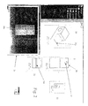
- FIG. 2 an example of a graphic display of an object according to the present invention is shown.
- the display shows depictions of the object from various perspectives.
- the object is shown as an isometric projection 20, and the front 21, left 22 and top 23 views are shown. It is to be understood that other views could also be shown, such as the right, back and bottom views.
- a three dimensional representation of the object is shown in a separate window 24 ("3D viewer"). In the three dimensional viewer, the object can be rotated in three dimensions according to the user's instructions to visualize the object from whatever perspective the user prefers.
- the vantage point of the 3D viewer realigns so that it matches that of the view on which the cursor is placed.
- This realignment feature may be turned on or off, at the user's preference.
- the user has placed a cursor 25 on the front view 21 and has positioned the cursor so that it points to an edge 26 of the object in the drawing.
- the selected edge 26 will be displayed in blue so as to highlight it in contrast to the other edges being displayed, although any manner of distinguishing the edge from other edges in the drawing are within the scope of the invention.
- the selected edge will be highlighted in each of the other displayed views. In Fig. 2 , these edges are denoted as 26a in the isometric view 20, 26b in the top view 23 and 26c in the 3D viewer.
- an edge is selected simply by moving the cursor over the desired edge in any view. In other words, no separate action, such as clicking a button on a mouse, is needed. In this way, highlighting of an edge in every view is done automatically and quickly. The user can quickly move the cursor from edge to edge, and view to view, and the highlighting in all the views will automatically change as the cursor moves from edge to edge in any view. It should be understood that the process by which the user selects an edge or feature can be accomplished in many other ways. For example, the addition of the clicking of a mouse to select an edge is within the scope of the invention, as well as keyboard input, pull-down menu options, or other means. It should also be understood that in the preferred embodiment, highlighting of the selected edge is accomplished not only in every view of the drawing, but also in the 3D viewer.
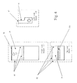
- Fig. 3 shows the isometric projection of Fig. 2 in enlarged form.
- the selected edge is 26a.
- Edge 26a which in the preferred embodiment of the invention becomes highlighted in blue as a result of the selection, is an edge of two adjoining faces, namely, faces 30 and 31.
- faces 30 and 31 are highlighted so as to provide more visual guidance to the user. Therefore, in Fig. 3 , the edges 37 of face 30 are highlighted in red, and the edges 38 of face 31 are also highlighted in red.
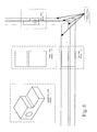
- Fig. 4 is an enlargement of the front, top and left views of Fig. 2 .
- the selected edge 26 appears in the front view (see 26) and top view (see 26b), but not in the left view.
- the selected edge is highlighted so as to distinguish it from the rest of the edges in the views.
- the visible edges of the faces adjoining the selected edge are highlighted in a manner so as to distinguish them from the selected edge as well as the rest of the edges. In the preferred embodiment, this is done by highlighting them in red.
- the three non-selected edges 41 of face 30 are highlighted in red.
- the three non-selected edges 42 of face 31 are highlighted in red.
- the one visible edge 42 of face 31 is red
- the one visible edge 41 of face 30 is red.
- the edge selected by the user in any view that is displayed, the edge selected by the user, if visible, will be colored blue, and the edges of adjoining faces, if visible, will be colored red. This provides the user with an immediate aid in distinguishing the features of the object, thereby enabling faster and more accurate comprehension of its geometry by the user.
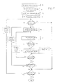
- Fig. 5 is a flow chart illustrating the preferred method used to determine highlighting in the preferred embodiment.
- Fig. 5 we begin with a drawing containing several views, and a 3D viewer showing the object in a separate window.
- a signal is received indicating that the cursor has moved 51
- an inquiry is made as to whether or not the cursor is on an edge of the object (step 52). If the answer is "no" then the system shows the position of the cursor relative to the object in each view.
- the position of the cursor can be represented by a simple cross or by a folding line.
- this view must be parallel to the view where the cursor is.
- a front view and a rear view are parallel
- a top view and a bottom view are parallel
- a right view and a left view are parallel.
- a folding line representing the track of the cursor is displayed in other cases, when views are not parallel (step 53).
- Fig. 6 is a graphic illustration showing folding lines between views. These folding lines link common edges of an object between views, and are another useful device for assisting the user in visualizing an object in three dimensions.
- step 54 an inquiry is made as to whether or not the selected edge is an edge of the current view (step 54).
- the current view is the view where the cursor was previously. If the answer is "no", then the current view changes so that the view selected by the user becomes the current view, and in addition, the 3D viewer realigns the 3D depiction of the object so that it is consonant with the selected view (step 55). It is to be understood that the resetting of the current view and the 3D viewer are each useful features of the preferred embodiment of the invention, which enhance the user interface, but need not be performed in every case.
- a generative view is a two dimensional view of the drawing that was automatically generated from the three dimensional model. Users may choose to create other views directly as a drawing, in which case the view is called non-generative, or "interactive.”
- step 56 If the selected view is a generative view (step 56, "yes"), then a method is employed, to be described below with reference to Fig. 7 , whereby the selected edge is highlighted in blue in every view, including the 3D viewer, and the edges of faces adjoining the selected edge are highlighted in red in every view, including the 3D viewer (step 58). All other edges remain un-highlighted.
- the details of the method of step 58 of the preferred embodiment of the invention are described with reference to Fig. 7 .
- step 56 In the event that the view is not a generative view (step 56, "no"), then the selected edge is highlighted in blue, and folding lines are displayed linking the end points of the selected edges and the corresponding edges in every view (step 57).
- Fig. 7 depicts the method of the present invention in flow chart form for highlighting the selected edge and edges of adjoining faces in every view. Therefore, according to the method of the invention, whenever it is discerned that the cursor is on an edge (step 70), a list of the faces adjoining the selected edge is obtained. This information is discerned from a database listing, for each edge, the faces that adjoin the edge (step 71). This list of faces, two faces in most cases, will be referred to as the "reference list”. In addition, a list of views in the drawing is obtained (step 72), and one of the views is selected as a starting point (step 73). The following process is then completed in iterative fashion for each view, using the reference list as a base.
- the initial inquiry that is made is whether or not a face of the reference list is displayed in the view. If not (step 74, "no"), that means that there is no edge displayed in the view that should be highlighted, in which case the highlighting portion of the method is skipped for this view, and the method proceeds to the next view (step 75). If there is a face of the reference list in the view (step 74, "yes"), then the first face in the "reference list" is selected, and its list of edges that are in the view is obtained from the database (step 76). For each of these edges, a list of faces adjoining the edge is obtained (step 77).
- This process is then repeated for the next face in the reference list. As indicated above, this process is repeated for each view. In addition, each time a new edge is selected by the user, the entire process as a whole is repeated.
- edges having correspondence to faces adjoining the selected edge will be eligible for highlighting. All other edges remain un-highlighted, or black in the preferred embodiment.
- the foregoing method can be applied to any object in any configuration capable of being defined by a CAD/CAM/CAE system, or any system used to display views of an object from varying viewpoints.
- the invention may be implemented in digital electronic circuitry, or in computer hardware, firmware, software, or in combinations of them.
- Apparatus of the invention may be implemented in a computer program product tangibly embodied in a machine-readable storage device for execution by a programmable processor; and method steps of the invention may be performed by a programmable processor executing a program of instructions to perform functions of the invention by operating on input data and generating output.
- the invention may advantageously be implemented in one or more computer programs that are executable on a programmable system including at least one programmable processor coupled to receive data and instructions from, and to transmit data and instructions to, a data storage system, at least one input device, and at least one output device.
- the application program may be implemented in a high-level procedural or object-oriented programming language, or in assembly or machine language if desired; and in any case, the language may be a compiled or interpreted language.
- a processor will receive instructions and data from a read-only memory and/or a random access memory.
- Storage devices suitable for tangibly embodying computer program instructions and data include all forms of nonvolatile memory, including by way of example semiconductor memory devices, such as EPROM, EEPROM, and flash memory devices; magnetic disks such as internal hard disks and removable disks; magneto-optical disks; and CD-ROM disks. Any of the foregoing may be supplemented by, or incorporated in, specially designed ASICs (application-specific integrated circuits).
- ASICs application-specific integrated circuits
Landscapes
- Engineering & Computer Science (AREA)
- Computer Graphics (AREA)
- Computer Hardware Design (AREA)
- General Engineering & Computer Science (AREA)
- Software Systems (AREA)
- Physics & Mathematics (AREA)
- General Physics & Mathematics (AREA)
- Theoretical Computer Science (AREA)
- Processing Or Creating Images (AREA)
- User Interface Of Digital Computer (AREA)
Claims (8)
- CAD/CAM-Computersystem-Bedienverfahren zur Verwendung mit einem System, das fähig ist, mehrere Ansichten eines Objekts aus verschiedenen Blickwinkeln anzuzeigen, wobei das Verfahren Folgendes umfasst:- Anzeigen mindestens einer Ansicht eines Objekts,- Empfangen (52, 70) einer Eingabe von einem Benutzer, die eine Darstellung eines Randes des Objekts auswählt,- Umgestalten (58, 79) des Aussehens der Darstellung des ausgewählten Randes des Objekts, um den ausgewählten Rand vom Rest des Objekts unterscheidbar zu machen,
dadurch gekennzeichnet, dass das Verfahren ferner folgende Schritte umfasst:- Identifizieren (71 - 76) aller Ränder aller an den ausgewählten Rand angrenzenden Flächen und- Umgestalten (58, 80) des Aussehens der Darstellung all dieser Ränder all der an den ausgewählten Rand angrenzenden Flächen in jeder der angezeigten Ansichten des Objekts, in der sie sichtbar sind. - Verfahren nach Anspruch 1, dadurch gekennzeichnet, dass der Schritt des Identifizierens von Rändern von Flächen, die an den ausgewählten Rand angrenzen, nach einer Liste von an den ausgewählten Rand angrenzenden Flächen ausgeführt wird, wobei die Liste aus einer Datenbank erkennt wird (71), die für jeden Rand die Flächen auflistet, die an den ausgewählten Rand angrenzen.
- Verfahren nach Anspruch 2, dadurch gekennzeichnet, dass der Schritt des Identifizierens von Rändern von Flächen, die an den ausgewählten Rand angrenzen, Folgendes umfasst:- Erhalten (71) der Liste von Flächen, die an den ausgewählten Rand angrenzen, aus einer Datenbank,- Speichern der Liste von Flächen und- Erhalten (76) einer Liste der Ränder für jede Fläche in der gespeicherten Liste aus der Datenbank.
- Verfahren nach Anspruch 1, 2 oder 3, dadurch gekennzeichnet, dass:- der Schritt des Umgestaltens des Aussehens der Darstellung des ausgewählten Randes des Objekts ausgeführt wird:- in der aktuellen Ansicht, um den ausgewählten Rand vom Rest des Objekts visuell unterscheidbar zu machen, und- in jeder anderen angezeigten Ansicht, in der er sichtbar ist, um den ausgewählten Rand vom Rest des Objekts visuell unterscheidbar zu machen,und dadurch gekennzeichnet, dass:- der Schritt des Umgestaltens des Aussehens der Darstellung der Ränder von Flächen des Objekts, die an den ausgewählten Rand angrenzen, ausgeführt wird:- in der aktuellen Ansicht und- in jeder anderen angezeigten Ansicht, in der sie sichtbar sind, um die angrenzenden Flächen vom Rest des Objekts und vom ausgewählten Rand visuell unterscheidbar zu machen.
- Verfahren nach einem der Ansprüche 1 bis 4, dadurch gekennzeichnet, dass der Schritt des Umgestaltens des Aussehens der Darstellung des ausgewählten Randes das Ändern seiner Anzeigefarbe umfasst.
- Verfahren nach einem der Ansprüche 1 bis 5, dadurch gekennzeichnet, dass das Verfahren nach dem Schritt des Empfangens einer Eingabe vom Benutzer ferner folgende Schritte umfasst:- Zugreifen auf eine Datenbank, die Informationen enthält, welche die dreidimensionale Gestaltung des Objekts betreffen, und- Bestimmen von Folgendem aus der Datenbank:- die Position der Darstellung des Randes des Objekts, die der Darstellung des vom Benutzer ausgewählten Randes entspricht, in jeder Ansicht und- die Position der Darstellung der Ränder von Flächen des Objekts, die an den ausgewählten Rand angrenzen, in jeder Ansicht,und dadurch gekennzeichnet, dass:- das Umgestalten des Aussehens der entsprechenden Darstellung des ausgewählten Randes des Objekts und der Darstellung der entsprechenden Ränder von Flächen des Objekts, die an den ausgewählten Rand angrenzen, in jeder Ansicht ausgeführt wird, in welcher sie sichtbar sind, um sie vom Rest des Objekts visuell unterscheidbar zu machen.
- Computerprogrammprodukt in einem maschinenlesbaren Speichergerät zum Ausführen durch einen programmierbaren Prozessor, umfassend Codemittel zum Umsetzen der Schritte nach einem der Ansprüche 1 bis 6.
- Cad/Cam-Vorrichtung, Folgendes umfassend:- ein Eingabegerät,- eine zentrale Recheneinheit,- ein Speichergerät zum Speichern von Daten und- ein Anzeigegerät,
wobei die zentrale Recheneinheit ein Anwendungsprogramm abarbeitet, das Code zum Umsetzen der Schritte nach einem der Ansprüche 1 bis 6 umfasst.
Applications Claiming Priority (2)
| Application Number | Priority Date | Filing Date | Title |
|---|---|---|---|
| US590977 | 1990-10-01 | ||
| US09/590,977 US6654027B1 (en) | 2000-06-09 | 2000-06-09 | Tool for three-dimensional analysis of a drawing |
Publications (3)
| Publication Number | Publication Date |
|---|---|
| EP1162575A2 EP1162575A2 (de) | 2001-12-12 |
| EP1162575A3 EP1162575A3 (de) | 2005-10-12 |
| EP1162575B1 true EP1162575B1 (de) | 2012-01-18 |
Family
ID=24364504
Family Applications (1)
| Application Number | Title | Priority Date | Filing Date |
|---|---|---|---|
| EP01401404A Expired - Lifetime EP1162575B1 (de) | 2000-06-09 | 2001-05-29 | Werkzeug zur dreidimensionalen Analyse einer Zeichnung |
Country Status (5)
| Country | Link |
|---|---|
| US (1) | US6654027B1 (de) |
| EP (1) | EP1162575B1 (de) |
| JP (1) | JP3762663B2 (de) |
| AT (1) | ATE542200T1 (de) |
| CA (1) | CA2349750C (de) |
Families Citing this family (31)
| Publication number | Priority date | Publication date | Assignee | Title |
|---|---|---|---|---|
| US7502027B1 (en) * | 1999-09-13 | 2009-03-10 | Solidworks Corporation | Electronic drawing viewer |
| JP2001337996A (ja) * | 2000-05-24 | 2001-12-07 | Canon Inc | 画像処理装置及びその制御方法並びに記憶媒体 |
| DE10031042A1 (de) * | 2000-06-26 | 2002-01-03 | Autodesk Inc | Erzeugen einer 2D-Ansicht eines 3D-Modells |
| AU2003285078A1 (en) * | 2002-10-31 | 2004-06-07 | Medtronic, Inc. | Distributed system for neurostimulation therapy programming |
| WO2004041351A1 (en) * | 2002-10-31 | 2004-05-21 | Medtronic, Inc. | Method and device for applying filter information to identify combinations of electrodes |
| US7933655B2 (en) * | 2002-10-31 | 2011-04-26 | Medtronic, Inc. | Neurostimulation therapy manipulation |
| DE60307882T2 (de) * | 2002-10-31 | 2007-03-15 | Medtronic, Inc., Minneapolis | Fehlersichere programmierung einer implantierbaren medizinischen vorrichtung |
| US7499048B2 (en) * | 2002-10-31 | 2009-03-03 | Medtronic, Inc. | Body region indication |
| EP1672548A1 (de) * | 2004-12-20 | 2006-06-21 | Dassault Systèmes | Prozess und System für die Darstellung eines Objektes in einer Ansicht mit Hilfe einer Produkt-Lebenszyklus-Verwaltungs-Datenbank |
| US7913190B2 (en) * | 2005-07-18 | 2011-03-22 | Dassault Systèmes | Method, system and software for visualizing 3D models |
| US7346408B2 (en) * | 2005-09-06 | 2008-03-18 | Esko Ip Nv | Two-dimensional graphics for incorporating on three-dimensional objects |
| CN100501749C (zh) * | 2005-09-08 | 2009-06-17 | 鸿富锦精密工业(深圳)有限公司 | 零件视图绘制系统及方法 |
| EP1804183B1 (de) * | 2005-12-30 | 2017-06-21 | Dassault Systèmes | Verfahren zur Auswahl von Objekten in einer PLM-Datenbank und Vorrichtung zur Implementierung dieses Verfahrens. |
| US7873237B2 (en) * | 2006-02-17 | 2011-01-18 | Dassault Systèmes | Degrading 3D information |
| US7724252B2 (en) * | 2006-08-14 | 2010-05-25 | Gaetano Mazzanti | Method for the editing of three-dimensional graphic models |
| US20080088621A1 (en) * | 2006-10-11 | 2008-04-17 | Jean-Jacques Grimaud | Follower method for three dimensional images |
| US8471873B2 (en) * | 2006-10-17 | 2013-06-25 | Oracle America, Inc. | Enhanced UI operations leveraging derivative visual representation |
| US20080297503A1 (en) * | 2007-05-30 | 2008-12-04 | John Dickinson | System and method for reconstructing a 3D solid model from a 2D line drawing |
| CN103370099B (zh) | 2011-02-18 | 2016-01-13 | 美敦力公司 | 具有可调节支架的医疗装置编程器 |
| US8532775B2 (en) | 2011-02-18 | 2013-09-10 | Medtronic, Inc. | Modular medical device programmer |
| CN102650998A (zh) * | 2011-02-28 | 2012-08-29 | 鸿富锦精密工业(深圳)有限公司 | 外观设计专利展示系统及方法 |
| JP5652495B2 (ja) * | 2012-07-31 | 2015-01-14 | キヤノンマーケティングジャパン株式会社 | 情報処理装置、その制御方法、及びプログラム |
| US9830405B2 (en) * | 2013-05-29 | 2017-11-28 | Siemens Product Lifecycle Management Software Inc. | System and method for providing sketch dimensions for a drawing view |
| EP2811463B1 (de) * | 2013-06-04 | 2018-11-21 | Dassault Systèmes | Entwurf eines 3D-modellierten Objekts mit 2D-Ansichten |
| EP2874118B1 (de) | 2013-11-18 | 2017-08-02 | Dassault Systèmes | Berechnung von Kameraparametern |
| EP3032495B1 (de) | 2014-12-10 | 2019-11-13 | Dassault Systèmes | Texturierung eines 3D-modellierten Objekts |
| EP3188033B1 (de) | 2015-12-31 | 2024-02-14 | Dassault Systèmes | Rekonstruktion eines 3d-modellierten objekts |
| US10055811B2 (en) | 2016-05-12 | 2018-08-21 | Caterpillar Inc. | System and method for generating interactive 2D projection of 3D model |
| EP3293705B1 (de) | 2016-09-12 | 2022-11-16 | Dassault Systèmes | 3d-rekonstruktion eines realen objekts aus einer tiefenkarte |
| US11429759B2 (en) * | 2019-11-18 | 2022-08-30 | Dassault Systemes Solidworks Corporation | Method for selecting multiple edges and faces in modeled object |
| US12400044B2 (en) * | 2020-02-13 | 2025-08-26 | Mitsubishi Electric Corporation | Dimension creation device, dimension creation method, and recording medium |
Family Cites Families (7)
| Publication number | Priority date | Publication date | Assignee | Title |
|---|---|---|---|---|
| NL8600831A (nl) * | 1986-04-02 | 1987-11-02 | Oce Nederland Bv | Werkwijze voor het opwekken en bewerken van modellen van twee- of driedimensionale objecten in een computer en voor het weergeven van die modellen op een display. |
| JPH08147498A (ja) * | 1994-11-22 | 1996-06-07 | Pfu Ltd | 3次元モデルの要素選択方式 |
| US6016147A (en) * | 1995-05-08 | 2000-01-18 | Autodesk, Inc. | Method and system for interactively determining and displaying geometric relationships between three dimensional objects based on predetermined geometric constraints and position of an input device |
| US5815154A (en) * | 1995-12-20 | 1998-09-29 | Solidworks Corporation | Graphical browser system for displaying and manipulating a computer model |
| US6256595B1 (en) * | 1998-03-04 | 2001-07-03 | Amada Company, Limited | Apparatus and method for manually selecting, displaying, and repositioning dimensions of a part model |
| US6285369B1 (en) * | 1998-05-12 | 2001-09-04 | Autodesk, Inc. | Electronic notebook for maintaining design information |
| US6295069B1 (en) * | 1998-08-18 | 2001-09-25 | Alventive, Inc. | Three dimensional computer graphics tool facilitating movement of displayed object |
-
2000
- 2000-06-09 US US09/590,977 patent/US6654027B1/en not_active Expired - Lifetime
-
2001
- 2001-05-29 AT AT01401404T patent/ATE542200T1/de active
- 2001-05-29 EP EP01401404A patent/EP1162575B1/de not_active Expired - Lifetime
- 2001-06-06 CA CA002349750A patent/CA2349750C/en not_active Expired - Lifetime
- 2001-06-11 JP JP2001175309A patent/JP3762663B2/ja not_active Expired - Lifetime
Also Published As
| Publication number | Publication date |
|---|---|
| EP1162575A3 (de) | 2005-10-12 |
| EP1162575A2 (de) | 2001-12-12 |
| US6654027B1 (en) | 2003-11-25 |
| JP3762663B2 (ja) | 2006-04-05 |
| CA2349750A1 (en) | 2001-12-09 |
| ATE542200T1 (de) | 2012-02-15 |
| JP2002042173A (ja) | 2002-02-08 |
| CA2349750C (en) | 2005-01-04 |
Similar Documents
| Publication | Publication Date | Title |
|---|---|---|
| EP1162575B1 (de) | Werkzeug zur dreidimensionalen Analyse einer Zeichnung | |
| EP1035464B1 (de) | Auswahlnavigator | |
| US6904393B2 (en) | Apparatus and method for manually selecting, displaying, and repositioning dimensions of a part model | |
| CA2358172C (en) | Annotation management | |
| US6219049B1 (en) | Mate inferencing | |
| US7737966B2 (en) | Method, apparatus, and system for processing geometric data of assembled parts | |
| US20030071810A1 (en) | Simultaneous use of 2D and 3D modeling data | |
| JP2004288170A (ja) | 三次元モデル検索方法及びシステム | |
| US10169493B2 (en) | Method for manipulating a computer aided design (CAD) model, computer program product and server therefore | |
| KR20080044827A (ko) | 컴퓨터로 만든 드로잉(drawing) 환경에서의 객체 간결합 | |
| TWI292540B (en) | Semiconductor test data analysis system, method for displaying therein, and method for analyzing semiconductor test data implemented therein | |
| US7420556B2 (en) | Information processing method and information processing apparatus | |
| US20080062195A1 (en) | Method for coordinated drawing review of realted cad drawings | |
| EP1116190B1 (de) | Verbindungsinferenzsystem und verfahren | |
| US7554544B2 (en) | Just-in-time user interface layout | |
| JPH11296571A (ja) | 干渉チェック装置およびそのプログラム記録媒体 | |
| Tching et al. | IM-sgi: An interface model for shape grammar implementations | |
| CN120407833B (zh) | 结合智能图层分级技术的cad图纸显示方法及系统 | |
| US20040049306A1 (en) | Simplified model creation assisting apparatus | |
| JPH06149962A (ja) | メニュー表示方式 | |
| WO2001090923A2 (en) | Method and apparatus for simplified dimensioning of mechanical design | |
| Davies et al. | Towards integration: draughting and 3-D modelling | |
| CA2351977A1 (en) | Automated item selection for computer programs | |
| JPH09114652A (ja) | 曖昧さを含む要求仕様記述方法 |
Legal Events
| Date | Code | Title | Description |
|---|---|---|---|
| PUAI | Public reference made under article 153(3) epc to a published international application that has entered the european phase |
Free format text: ORIGINAL CODE: 0009012 |
|
| AK | Designated contracting states |
Kind code of ref document: A2 Designated state(s): AT BE CH CY DE DK ES FI FR GB GR IE IT LI LU MC NL PT SE TR |
|
| AX | Request for extension of the european patent |
Free format text: AL;LT;LV;MK;RO;SI |
|
| PUAL | Search report despatched |
Free format text: ORIGINAL CODE: 0009013 |
|
| AK | Designated contracting states |
Kind code of ref document: A3 Designated state(s): AT BE CH CY DE DK ES FI FR GB GR IE IT LI LU MC NL PT SE TR |
|
| AX | Request for extension of the european patent |
Extension state: AL LT LV MK RO SI |
|
| 17P | Request for examination filed |
Effective date: 20060328 |
|
| AKX | Designation fees paid |
Designated state(s): AT BE CH CY DE DK ES FI FR GB GR IE IT LI LU MC NL PT SE TR |
|
| 17Q | First examination report despatched |
Effective date: 20060823 |
|
| REG | Reference to a national code |
Ref country code: DE Ref legal event code: R079 Ref document number: 60145982 Country of ref document: DE Free format text: PREVIOUS MAIN CLASS: G06T0017400000 Ipc: G06T0019000000 |
|
| GRAP | Despatch of communication of intention to grant a patent |
Free format text: ORIGINAL CODE: EPIDOSNIGR1 |
|
| RIC1 | Information provided on ipc code assigned before grant |
Ipc: G06T 19/00 20110101AFI20110824BHEP |
|
| GRAS | Grant fee paid |
Free format text: ORIGINAL CODE: EPIDOSNIGR3 |
|
| GRAA | (expected) grant |
Free format text: ORIGINAL CODE: 0009210 |
|
| AK | Designated contracting states |
Kind code of ref document: B1 Designated state(s): AT BE CH CY DE DK ES FI FR GB GR IE IT LI LU MC NL PT SE TR |
|
| REG | Reference to a national code |
Ref country code: GB Ref legal event code: FG4D |
|
| REG | Reference to a national code |
Ref country code: CH Ref legal event code: EP |
|
| REG | Reference to a national code |
Ref country code: AT Ref legal event code: REF Ref document number: 542200 Country of ref document: AT Kind code of ref document: T Effective date: 20120215 Ref country code: IE Ref legal event code: FG4D |
|
| REG | Reference to a national code |
Ref country code: DE Ref legal event code: R096 Ref document number: 60145982 Country of ref document: DE Effective date: 20120315 |
|
| REG | Reference to a national code |
Ref country code: SE Ref legal event code: TRGR |
|
| REG | Reference to a national code |
Ref country code: NL Ref legal event code: VDEP Effective date: 20120118 |
|
| PG25 | Lapsed in a contracting state [announced via postgrant information from national office to epo] |
Ref country code: NL Free format text: LAPSE BECAUSE OF FAILURE TO SUBMIT A TRANSLATION OF THE DESCRIPTION OR TO PAY THE FEE WITHIN THE PRESCRIBED TIME-LIMIT Effective date: 20120118 Ref country code: BE Free format text: LAPSE BECAUSE OF FAILURE TO SUBMIT A TRANSLATION OF THE DESCRIPTION OR TO PAY THE FEE WITHIN THE PRESCRIBED TIME-LIMIT Effective date: 20120118 |
|
| PG25 | Lapsed in a contracting state [announced via postgrant information from national office to epo] |
Ref country code: GR Free format text: LAPSE BECAUSE OF FAILURE TO SUBMIT A TRANSLATION OF THE DESCRIPTION OR TO PAY THE FEE WITHIN THE PRESCRIBED TIME-LIMIT Effective date: 20120419 Ref country code: PT Free format text: LAPSE BECAUSE OF FAILURE TO SUBMIT A TRANSLATION OF THE DESCRIPTION OR TO PAY THE FEE WITHIN THE PRESCRIBED TIME-LIMIT Effective date: 20120518 Ref country code: FI Free format text: LAPSE BECAUSE OF FAILURE TO SUBMIT A TRANSLATION OF THE DESCRIPTION OR TO PAY THE FEE WITHIN THE PRESCRIBED TIME-LIMIT Effective date: 20120118 |
|
| REG | Reference to a national code |
Ref country code: AT Ref legal event code: MK05 Ref document number: 542200 Country of ref document: AT Kind code of ref document: T Effective date: 20120118 |
|
| PG25 | Lapsed in a contracting state [announced via postgrant information from national office to epo] |
Ref country code: CY Free format text: LAPSE BECAUSE OF FAILURE TO SUBMIT A TRANSLATION OF THE DESCRIPTION OR TO PAY THE FEE WITHIN THE PRESCRIBED TIME-LIMIT Effective date: 20120118 |
|
| PG25 | Lapsed in a contracting state [announced via postgrant information from national office to epo] |
Ref country code: DK Free format text: LAPSE BECAUSE OF FAILURE TO SUBMIT A TRANSLATION OF THE DESCRIPTION OR TO PAY THE FEE WITHIN THE PRESCRIBED TIME-LIMIT Effective date: 20120118 |
|
| PLBE | No opposition filed within time limit |
Free format text: ORIGINAL CODE: 0009261 |
|
| STAA | Information on the status of an ep patent application or granted ep patent |
Free format text: STATUS: NO OPPOSITION FILED WITHIN TIME LIMIT |
|
| 26N | No opposition filed |
Effective date: 20121019 |
|
| PG25 | Lapsed in a contracting state [announced via postgrant information from national office to epo] |
Ref country code: MC Free format text: LAPSE BECAUSE OF NON-PAYMENT OF DUE FEES Effective date: 20120531 |
|
| REG | Reference to a national code |
Ref country code: CH Ref legal event code: PL |
|
| PG25 | Lapsed in a contracting state [announced via postgrant information from national office to epo] |
Ref country code: AT Free format text: LAPSE BECAUSE OF FAILURE TO SUBMIT A TRANSLATION OF THE DESCRIPTION OR TO PAY THE FEE WITHIN THE PRESCRIBED TIME-LIMIT Effective date: 20120118 Ref country code: CH Free format text: LAPSE BECAUSE OF NON-PAYMENT OF DUE FEES Effective date: 20120531 Ref country code: LI Free format text: LAPSE BECAUSE OF NON-PAYMENT OF DUE FEES Effective date: 20120531 |
|
| REG | Reference to a national code |
Ref country code: DE Ref legal event code: R097 Ref document number: 60145982 Country of ref document: DE Effective date: 20121019 |
|
| REG | Reference to a national code |
Ref country code: IE Ref legal event code: MM4A |
|
| PG25 | Lapsed in a contracting state [announced via postgrant information from national office to epo] |
Ref country code: IE Free format text: LAPSE BECAUSE OF NON-PAYMENT OF DUE FEES Effective date: 20120529 Ref country code: ES Free format text: LAPSE BECAUSE OF FAILURE TO SUBMIT A TRANSLATION OF THE DESCRIPTION OR TO PAY THE FEE WITHIN THE PRESCRIBED TIME-LIMIT Effective date: 20120429 |
|
| PG25 | Lapsed in a contracting state [announced via postgrant information from national office to epo] |
Ref country code: TR Free format text: LAPSE BECAUSE OF FAILURE TO SUBMIT A TRANSLATION OF THE DESCRIPTION OR TO PAY THE FEE WITHIN THE PRESCRIBED TIME-LIMIT Effective date: 20120118 |
|
| PG25 | Lapsed in a contracting state [announced via postgrant information from national office to epo] |
Ref country code: LU Free format text: LAPSE BECAUSE OF NON-PAYMENT OF DUE FEES Effective date: 20120529 |
|
| REG | Reference to a national code |
Ref country code: FR Ref legal event code: PLFP Year of fee payment: 16 |
|
| REG | Reference to a national code |
Ref country code: FR Ref legal event code: CD Owner name: DASSAULT SYSTEMES, FR Effective date: 20170227 Ref country code: FR Ref legal event code: CJ Effective date: 20170227 |
|
| REG | Reference to a national code |
Ref country code: FR Ref legal event code: PLFP Year of fee payment: 17 |
|
| REG | Reference to a national code |
Ref country code: DE Ref legal event code: R082 Ref document number: 60145982 Country of ref document: DE Representative=s name: HORN KLEIMANN WAITZHOFER PATENTANWAELTE PARTG , DE Ref country code: DE Ref legal event code: R081 Ref document number: 60145982 Country of ref document: DE Owner name: DASSAULT SYSTEMES S.E., FR Free format text: FORMER OWNER: DASSAULT SYSTEMES S.A., SURESNES, FR |
|
| REG | Reference to a national code |
Ref country code: FR Ref legal event code: PLFP Year of fee payment: 18 |
|
| PGFP | Annual fee paid to national office [announced via postgrant information from national office to epo] |
Ref country code: FR Payment date: 20200522 Year of fee payment: 20 Ref country code: DE Payment date: 20200520 Year of fee payment: 20 |
|
| PGFP | Annual fee paid to national office [announced via postgrant information from national office to epo] |
Ref country code: IT Payment date: 20200528 Year of fee payment: 20 Ref country code: SE Payment date: 20200527 Year of fee payment: 20 Ref country code: GB Payment date: 20200527 Year of fee payment: 20 |
|
| REG | Reference to a national code |
Ref country code: DE Ref legal event code: R071 Ref document number: 60145982 Country of ref document: DE |
|
| REG | Reference to a national code |
Ref country code: GB Ref legal event code: PE20 Expiry date: 20210528 |
|
| REG | Reference to a national code |
Ref country code: SE Ref legal event code: EUG |
|
| PG25 | Lapsed in a contracting state [announced via postgrant information from national office to epo] |
Ref country code: GB Free format text: LAPSE BECAUSE OF EXPIRATION OF PROTECTION Effective date: 20210528 |
|
| P01 | Opt-out of the competence of the unified patent court (upc) registered |
Effective date: 20230527 |