EP1162341A1 - Floor sealing for a door leaf - Google Patents
Floor sealing for a door leaf Download PDFInfo
- Publication number
- EP1162341A1 EP1162341A1 EP01105667A EP01105667A EP1162341A1 EP 1162341 A1 EP1162341 A1 EP 1162341A1 EP 01105667 A EP01105667 A EP 01105667A EP 01105667 A EP01105667 A EP 01105667A EP 1162341 A1 EP1162341 A1 EP 1162341A1
- Authority
- EP
- European Patent Office
- Prior art keywords
- profile
- sealing element
- sealing
- floor seal
- seal according
- Prior art date
- Legal status (The legal status is an assumption and is not a legal conclusion. Google has not performed a legal analysis and makes no representation as to the accuracy of the status listed.)
- Granted
Links
Images

Classifications
-
- E—FIXED CONSTRUCTIONS
- E06—DOORS, WINDOWS, SHUTTERS, OR ROLLER BLINDS IN GENERAL; LADDERS
- E06B—FIXED OR MOVABLE CLOSURES FOR OPENINGS IN BUILDINGS, VEHICLES, FENCES OR LIKE ENCLOSURES IN GENERAL, e.g. DOORS, WINDOWS, BLINDS, GATES
- E06B7/00—Special arrangements or measures in connection with doors or windows
- E06B7/16—Sealing arrangements on wings or parts co-operating with the wings
- E06B7/18—Sealing arrangements on wings or parts co-operating with the wings by means of movable edgings, e.g. draught sealings additionally used for bolting, e.g. by spring force or with operating lever
- E06B7/20—Sealing arrangements on wings or parts co-operating with the wings by means of movable edgings, e.g. draught sealings additionally used for bolting, e.g. by spring force or with operating lever automatically withdrawn when the wing is opened, e.g. by means of magnetic attraction, a pin or an inclined surface, especially for sills
- E06B7/21—Sealing arrangements on wings or parts co-operating with the wings by means of movable edgings, e.g. draught sealings additionally used for bolting, e.g. by spring force or with operating lever automatically withdrawn when the wing is opened, e.g. by means of magnetic attraction, a pin or an inclined surface, especially for sills with sealing strip movable in plane of wing
Landscapes
- Engineering & Computer Science (AREA)
- Civil Engineering (AREA)
- Structural Engineering (AREA)
- Specific Sealing Or Ventilating Devices For Doors And Windows (AREA)
- Seal Device For Vehicle (AREA)
Abstract
Description
Die Erfindung betrifft eine Bodendichtung für ein Türblatt, mit einem im wesentlichen umgekehrt U-förmigen Einbauprofil, das in einer Nut an der Unterseite des Türblatts befestigbar ist, mit einer im Einbauprofil geführten Schiene, die mit Hilfe einer beim Schließen der Tür betätigten Mechanik gegen Federkraft aus einer nach oben zurückgezogenen Ruhestellung in eine abgesenkte Dichtstellung bewegbar ist, und mit einem an der Schiene befestigten Abdichtelement aus elastischem Material.The invention relates to a floor seal for a door leaf, with an essentially reversed U-shaped mounting profile, which is in a groove at the bottom of the Door leaf can be fastened, with a rail guided in the installation profile, which with the help a mechanism operated against spring force when closing the door from one to retracted rest position at the top can be moved into a lowered sealing position, and with an elastic sealing element attached to the rail Material.
Solche insgesamt schienenförmigen Dichtanordnungen für die Unterseite der Türblätter von (schwellenlosen) Türen sind vielfältig bekannt. Sie dienen im geschlossenen Zustand der Tür dem Abdichten des Luftspalts zwischen dem Türblatt und dem Fußboden gegen den Durchtritt von Geräuschen, Gerüchen, Rauch etc. Gemeinsam ist allen Türbodendichtungen dieser Art, dass die Abdichtleiste eine zufriedenstellende Dichtwirkung zwischen dem Fußboden und der von der Mechanik beim Schließen der Tür im wesentlichen vertikal bewegten Schiene - an der das Abdichtelement befestigt ist - herstellt. Es bleibt jedoch ein Luft- und damit Durchtrittspalt zwischen der Schiene und dem sie dreiseitig umgebenden Einbauprofil. Man hat daher unterschiedliche Maßnahmen zum Schließen dieses Spalts vorgeschlagen. Sie bestehen beispielsweise aus separaten Dichtleisten zwischen der Schiene und dem Einbauprofil bis zu Verlängerungsschenkeln des Abdichtelements, welche sich zwischen dem Einbauprofil und der Schiene nach oben erstrecken und an den Innenseiten der Einbauprofil-Schenkel anliegen (EP-B1-0 338 974). Derartige Maßnahmen vergrößern aber den konstruktiven Aufwand und gefährden die dauerhafte Funktion der automatischen Türbodendichtung, weil es zu starker Reibung an dem bzw. den Abdichtelement(en) und leicht zu Verklemmungen zwischen der Schiene und dem Einbauprofil kommt. Ausserdem muss entweder die Schiene schmaler ausgeführt werden, was die Verkantungsgefahr erhöht, oder das Einbauprofil breiter, was wegen der relativ geringen Dicke von Türblättern meist problematisch ist.Such overall rail-shaped sealing arrangements for the underside of the door leaves of (thresholdless) doors are widely known. They serve in the closed Condition of the door sealing the air gap between the door leaf and the floor against the passage of noises, smells, smoke etc. Common to all door floor seals of this type is that the sealing strip is a satisfactory sealing effect between the floor and that of the mechanics when closing the door essentially vertically moving rail - on which the Sealing element is attached - manufactures. However, there remains an air gap and thus a passage between the rail and the mounting profile surrounding it on three sides. Different measures to close this gap have therefore been proposed. For example, they consist of separate sealing strips between the Rail and the installation profile up to extension legs of the sealing element, which extend upwards between the mounting profile and the rail and lie on the inside of the mounting profile legs (EP-B1-0 338 974). Such However, measures increase the design effort and endanger it permanent function of the automatic door floor seal because it is too strong Friction on the sealing element (s) and easy to jam comes between the rail and the mounting profile. In addition, either Rail are made narrower, which increases the risk of jamming, or that Installation profile wider, which is mostly due to the relatively small thickness of door leaves is problematic.
Vor diesem Hintergrund liegt der Erfindung die Aufgabe zugrunde, eine mit geringem Aufwand herstellbare, funktionssichere und vollständig abdichtende automatische Türbodendichtung anzugeben.Against this background, the invention has for its object one with little Effortless, reliable and completely sealing automatic Specify door seal.
Diese Aufgabe wird erfindungsgemäß dadurch gelöst, dass das Abdichtelement mindestens einen Schenkel des Einbauprofils mit einem flachleistenförmigen Fortsatz umfasst und auf der Aussenseite des Schenkels anliegt. Weil das Einbauprofil im Türblatt fest und damit abgedichtet gehalten ist, gibt es auf diese Weise - weil das Abdichtelement das Einbauprofil mindestens auf einer Seite umgreift - im Bereich des Türblatts keine "Luftbrücke" mehr, d.h. keine Durchlaßschlitz-Kombination für Luft und von dieser übertragene Geräusche, Gerüche u. dgl. Zugleich ist eine genaue, reibungsarme und klemmfreie Führung der Schiene im Einbauprofil möglich; deshalb können sowohl das Einbauprofil als auch die Schiene relativ schmal gehalten werden, so dass die für die Fortsätze des Abdichtelements, welche die Schenkel des Einbauprofils umgreifen, erforderliche Verbreiterung der Türblattnut zur Verfügung steht. Schließlich ist der Austausch - etwa wegen Verschleisses - des aussen am Einbauprofil anliegenden Abdichtelements wesentlich einfacher zu bewerkstelligen als der eines innen anliegenden (einstückigen oder zweigeteilten) Abdichtelements.This object is achieved in that the sealing element at least one leg of the mounting profile with a flat bar Includes extension and rests on the outside of the leg. Because the installation profile in the door leaf and thus sealed, there is in this way - because the sealing element surrounds the installation profile on at least one side - No more "airlift" in the area of the door leaf, i.e. no passage slot combination for air and noises, smells, etc. transmitted by it the like At the same time, the rail is guided precisely, with little friction and without jamming Installation profile possible; therefore both the mounting profile and the rail can are kept relatively narrow, so that the for the extensions of the sealing element, which encompass the legs of the installation profile, required widening of the Door leaf groove is available. After all, the exchange is - perhaps because of wear - The sealing element that lies against the outside of the installation profile is essential easier to accomplish than that of an inside (one-piece or two-part) sealing element.
Von besonderem Vorteil ist ferner, dass das das Einbauprofil umgreifende Abdichtelement die Anpassung der Dichtungsqualität mit Hilfe unterschiedlich ausgebildeter Abdichtelemente im Zusammenwirken mit einer einzigen (das Einbauprofil und die Schiene einschließenden) Dichtungsmechanik ermöglicht, was einen erheblichen Rationalisierungseffekt und damit Kostenersparnisse mit sich bringt. So ist vorzugsweise vorgesehen, dass zwei flachleistenförmige Fortsätze beide Schenkel des Einbauprofils umfassen. Ferner kann der oder jeder Fortsatz des Abdichtelements aus einem flachen Hohlkammerprofil mit zwei parallelen Wandungen bestehen, was insbesondere die Schalldämmung wesentlich verbessert.It is also of particular advantage that the sealing element encompassing the installation profile the adjustment of the seal quality with the help of differently trained Sealing elements in cooperation with a single (the installation profile and the sealing mechanism, which includes the rail, which makes a considerable Rationalization effect and thus cost savings. So is preferably provided that two flat bar-shaped extensions both legs of the installation profile. Furthermore, the or each extension of the sealing element consist of a flat hollow section with two parallel walls, which in particular significantly improves sound insulation.
Eine Weiterbildung besteht darin, dass der/jeder Fortsatz sich parallel zum Schenkel des Einbauprofils erstreckt und mit einer Abkröpfung seines freien Randes aussenseitig am Schenkel anliegt. Eine stärkere Anpressung des Fortsatzes an die Aussenseite des Schenkels ergibt sich, wenn ein an der Wurzel des Fortsatzes am Abdichtelement ansetzender Stützschenkel sich schräg nach aussen und unten erstreckt; beim Bewegen des Abdichtelements in die Dichtstellung schwenkt dieser Stützschenkel den Fortsatz an den Schenkel des Einbauprofils im Sinne größerer Dichtwirkung heran. Es ist schließlich vorteilhaft, die einzelnen Abschnitte des Abdichtelements ihren jeweiligen Aufgaben dadurch optimal anzupassen, dass das Abdichtelement über seinen Querschnitt unterschiedliche Materialelastizitäten und -härten aufweist.A further development is that the / each extension is parallel to the leg of the built-in profile and with an offset of its free edge on the outside rests on the thigh. A stronger pressure of the extension on the Outside of the leg arises when a at the root of the extension Support leg attaching sealing element is inclined outwards and downwards extends; when moving the sealing element into the sealing position, it pivots Support leg the extension to the leg of the mounting profile in the sense of larger Sealing effect. Finally, it is advantageous to the individual sections of the Sealing element to optimally adapt to their respective tasks in that the Sealing element over its cross section different material elasticities and - has hardening.
Die Zeichnung veranschaulicht die Erfindung an Ausführungsbeispielen, darin zeigt:
- Fig. 1
- eine bevorzugte Ausführungsform der insgesamt schienenförmigen Tür-Bodendichtung im Querschnitt (ohne Türblatt) in der angehobenen Ruhestellung des Abdichtelements;
- Fig. 2
- eine der Fig. 1 entsprechende Darstellung in der abgesenkten Dichtstellung;
- Fig. 3
- eine (dem Stand der Technik zuzurechnende) Bodendichtung ohne das Einbauprofil umgreifende Fortsätze;
- Fig. 4
- eine erfindungsgemäße Bodendichtung mit einseitig umgreifendem Fortsatz des Abdichtelements;
- Fig. 5
- eine den Fig. 1 und 2 entsprechende Darstellung dieses Ausführungsbeispiels;
- Fig. 6
- eine Bodendichtung mit Fortsätzen in Form doppelwandiger Hohlkammerprofile;
- Fig. 7
- eine Bodendichtung gemäß Fig. 1 und 5 im Einbauzustand (Türblatt-Querschnitt hier und in den folgenden Fig. angedeutet);
- Fig. 8
- ein den Fig. 1 und 2 entsprechendes Ausführungsbeispiel der Bodendichtung mit abgewandeltem Einbauprofil;
- Fig. 9
- ein ebenfalls den Fig. 1 und 2 entsprechendes Ausführungsbeispiel mit einem andersartig abgewandelten Einbauprofil; und
- Fig. 10
- eine weitere Abwandlung des Einbauprofils.
- Fig. 1
- a preferred embodiment of the overall rail-shaped door bottom seal in cross section (without door leaf) in the raised rest position of the sealing element;
- Fig. 2
- a representation corresponding to Figure 1 in the lowered sealing position.
- Fig. 3
- a base seal (to be attributed to the prior art) without projections encompassing the installation profile;
- Fig. 4
- a floor seal according to the invention with a one-sided extension of the sealing element;
- Fig. 5
- a representation corresponding to Figures 1 and 2 of this embodiment.
- Fig. 6
- a floor seal with extensions in the form of double-walled hollow chamber profiles;
- Fig. 7
- a floor seal according to Figures 1 and 5 in the installed state (door leaf cross-section indicated here and in the following figures);
- Fig. 8
- 1 and 2 corresponding embodiment of the floor seal with a modified installation profile;
- Fig. 9
- an also corresponding to Figures 1 and 2 embodiment with a differently modified installation profile. and
- Fig. 10
- a further modification of the installation profile.
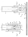
In einem Einbauprofil 1 (üblicherweise aus stranggepresstem Aluminium hergestellt),
welches einen umgekehrt U-förmigen Querschnitt hat und eine der Breite
des (nicht dargestellten) Türblatts entsprechende Länge aufweist, führt im Innern
eine - regelmäßig ebenfalls als Aluminium-Strangpressprofil ausgeführte -
Schiene 2. Diese ist, wie Fig. 2 im Vergleich zu Fig. 1 verdeutlicht, vertikal beweglich,
und zwischen dem Einbauprofil 1 und der Schiene 2 ist eine - nicht dargestellte,
aber hinlänglich bekannte - Mechanik angeordnet, welche beim Schließen
der Tür die Schiene 2 nach unten aus dem Einbauprofil 1 gegen Federkraft herausdrückt;
wird die Tür wieder geöffnet, zieht die Feder die Schiene 2 zurück.In an installation profile 1 (usually made from extruded aluminum),
which has an inverted U-shaped cross section and one of the width
of the (not shown) door leaf has the appropriate length, leads inside
one - also regularly designed as an extruded aluminum profile -
An der Schiene 2 ist ein im Ganzen mit 3 bezeichnetes Abdichtprofil angebracht;
im Beispiel mit der T-förmigen Leiste 4 in eine entsprechend geformte Nut 5 der
Schiene 2 eingeschoben. Auch das Abdichtprofil 3 erstreckt sich ebenso wie die
Schiene 2 und das Einbauprofil 1 über die gesamte Breite des Türblatts. Gefertigt
ist das Abdichtprofil 3 aus einem elastischen Material, wie Gummi, Kunststoff
o. dgl., wobei je nach Einsatzzweck der nachfolgend zu beschreibenden Abschnitte
unterschiedliche bzw. unterschiedlich elastische, harte oder weiche etc. Werkstoffe
eingesetzt und einstückig miteinander zum Abdichtelement 3 verbunden sein
können.On the
An die T-förmige Leiste 4 des Abdichtelements 3 schließt sich nach unten hin ein
Zentralabschnitt 6 an, welcher weiter nach unten von einem Bodenkontakt-Abschnitt
7 von im wesentlichen elliptischem Querschnitt gefolgt ist. Hohlkammern
8 und 9 erhöhen die Elastizität in Andruckrichtung des Abdichtelements.At the T-shaped
Beidseitig des Abschnitts 7 erstrecken sich Fortsätze 10 in Form von Flachleisten
nach oben und liegen jeweils mit einer Abkröpfung 11 an der Aussenseite der
Schenkel 1a des Einbauprofils 1 an.
Ebenfalls von den Seiten des Abschnitts 7 des Abdichtelements 3 ausgehend erstrecken
sich Stützschenkel 12 jeweils nach aussen und unten. Wird das Abdichtelement
3 von der Schiene 2 aus der in Fig. 1 dargestellten Ruhestellung in die in
Fig. 2 dargestellte (beginnende) Abdichtstellung - und im allgemeinen auch etwas
über die dargestellte Abdichtstellung hinaus - gegen den Boden 13 des von der Tür
unterteilten Raumes bewegt, so schwenken die Stützschenkel 12 die leistenförmigen
Fortsätze 10 mit ihren Abkröpfungen 1 1 gegen die Aussenseiten der Schenkel
1 a des Einbauprofils 1 und verstärken auf diese Weise die Abdichtung des Abdichtelements
3 gegenüber dem Einbauprofil 1 (welches seinerseits fest und ohne
jegliche Luft- und Schallbrücke im Türblatt befestigt ist).Also extend from the sides of the
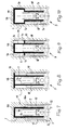
Die Fig. 3 bis 6 veranschaulichen, wie mit derselben Kombination aus Einbauprofil
1 und Schiene 2 (zuzüglich der nicht dargestellten Federmechanik zwischen
beiden) unterschiedliche Abdichtelemente 3 verwendet werden können, so dass
auf diese Weise - allein mit Hilfe eines anderen Abdichtelements 3 - unterschiedlichen
Anforderungen an die Qualität der Abdichtung Rechnung getragen werden
kann. Alle Darstellungen zeigen die Türbodendichtung in der zurückgezogenen
Ruhestellung, jedoch ist gestrichelt angedeutet, in welcher Lage sich das jeweilige
Abdichtelement 3 befindet, wenn die Abdichtstellung eingenommen wird.3 to 6 illustrate how with the same combination of mounting
Die in Fig. 3 gezeigte Türbodendichtung stellt praktisch den Stand der Technik dar
und wurde hier nur aufgenommen, um zu zeigen, dass die in Rede stehende
Konstruktion auch die Verwendung mit einem ganz einfachen, herkömmlichen
Abdichtelement 3 erlaubt. Während Fig. 5 das Ausführungsbeispiel der Fig. 1 und
2 wiederholt, zeigt Fig. 4 eine weniger anspruchsvolle Ausbildung, indem das
Abdichtelement 3 nur einen Fortsatz 10 aufweist, mit dem es an der Aussenseite
des einen Schenkels 1 a des Einbauprofils 1 anliegt. Demgegenüber sind die beidseitigen
Fortsätze 10 des Ausführungsbeispiels in Fig. 6 doppelwandig mit Hohlkammern
14 ausgebildet, und die Stützschenkel 12 gehen in die jeweils äussere
Wandung 10a der Fortsätze 10 über.The door floor seal shown in Fig. 3 represents practically the prior art
and was only included here to show that the one in question
Construction also use with a very simple,
Fig. 7 veranschaulicht den Einbau einer Türbodendichtung gemäß den Fig. 1 bzw.
5 in ein nur angedeutetes Türblatt 15. Die dafür im Türblatt 15 üblicherweise
vorgesehene Nut 16 hat einen verbreiterten Abschnitt 16a, so dass im (dargestellten)
Ruhezustand die Fortsätze 10 des Abdichtelements 3 Raum finden. Die Fig. 8
und 10 zeigen abgewandelte Querschnitte des Einbauprofils 1, und zwar ist die
bodenseitig im Türblatt 15 vorgesehene Nut über ihre ganze Tiefe mit der Breite der
Nut 16a in Fig. 7 ausgeführt. Dafür kragt der Steg 1b des Einbauprofils 1 beim
Ausführungsbeispiel der Fig. 8 seitlich über die Schenkel 1a aus, so dass die
Zentrierung der Dichtung im Türblatt gesichert ist. Gleiches gilt für das Ausführungsbeispiel
der Fig. 9, jedoch sind dort separate Ansätze 1c am Einbauprofil 1
vorgesehen. Im Falle der Fig. 10 ist das Einbauprofil 1 - unter Beibehaltung seiner
U-Förmigkeit - in seinem (im Ruhezustand) oberhalb der Fortsätze 10 befindlichen
Abschnitt auf die Breite der Nut 16a beidseitig ausgeweitet.FIG. 7 illustrates the installation of a door floor seal according to FIG. 1 or
5 in a
Claims (8)
Applications Claiming Priority (2)
| Application Number | Priority Date | Filing Date | Title |
|---|---|---|---|
| DE20005376U DE20005376U1 (en) | 2000-03-22 | 2000-03-22 | Floor seal for a door leaf |
| DE20005376U | 2000-03-22 |
Publications (2)
| Publication Number | Publication Date |
|---|---|
| EP1162341A1 true EP1162341A1 (en) | 2001-12-12 |
| EP1162341B1 EP1162341B1 (en) | 2003-01-29 |
Family
ID=7939212
Family Applications (1)
| Application Number | Title | Priority Date | Filing Date |
|---|---|---|---|
| EP01105667A Expired - Lifetime EP1162341B1 (en) | 2000-03-22 | 2001-03-07 | Floor sealing for a door leaf |
Country Status (3)
| Country | Link |
|---|---|
| EP (1) | EP1162341B1 (en) |
| AT (1) | ATE231947T1 (en) |
| DE (2) | DE20005376U1 (en) |
Cited By (6)
| Publication number | Priority date | Publication date | Assignee | Title |
|---|---|---|---|---|
| EP1460232A1 (en) * | 2003-03-19 | 2004-09-22 | Manfred Kross | Floor sealing of a door leaf |
| EP1905938A2 (en) | 2006-09-19 | 2008-04-02 | Planet GDZ AG | Door seal |
| WO2010057226A1 (en) * | 2008-11-12 | 2010-05-20 | Zwelakhe Winston Mahlangu | The door sealer |
| EP2378050A1 (en) | 2010-04-16 | 2011-10-19 | Luigi Geron | Automatic sealing for doors or windows leaves |
| WO2014029877A1 (en) * | 2012-08-23 | 2014-02-27 | Planet Gdz Ag | Door seal with two sealing planes |
| CN104895472A (en) * | 2014-11-17 | 2015-09-09 | 阿特玛无限公司 | Door sealing device |
Families Citing this family (5)
| Publication number | Priority date | Publication date | Assignee | Title |
|---|---|---|---|---|
| AT510200B1 (en) * | 2010-08-13 | 2012-05-15 | Christian Pfeifhofer | FLEXIBLE ROOM VENTILATION SYSTEM |
| CH705344A1 (en) * | 2011-08-02 | 2013-02-15 | Planet Gdz Ag | Seal for a barrier-free door. |
| EP2629027A1 (en) | 2012-02-14 | 2013-08-21 | Christian Pfeifhofer | Flexible room ventilation system |
| DE202015103304U1 (en) | 2015-06-23 | 2016-09-30 | Manfred Kross | Door leaf seal with roll seal |
| CN111734276B (en) * | 2020-06-22 | 2022-03-15 | 台州中穗科技有限公司 | Closed heat insulation window |
Citations (3)
| Publication number | Priority date | Publication date | Assignee | Title |
|---|---|---|---|---|
| DE900492C (en) * | 1952-02-02 | 1953-12-28 | Hans Willi | Closing device on a door without a threshold |
| US3871133A (en) * | 1974-01-14 | 1975-03-18 | Jr Chester W Ellingson | Door bottom weather sealing structure |
| EP0338974A2 (en) * | 1988-04-19 | 1989-10-25 | " Planet" Matthias Jaggi | Sealing-arrangement for doors without sill |
Family Cites Families (5)
| Publication number | Priority date | Publication date | Assignee | Title |
|---|---|---|---|---|
| DE1707395U (en) * | 1955-04-23 | 1955-09-22 | Heinz F W Suppus | DEVICE FOR SEALING AND CLOSING FLAP OPENINGS, IN PARTICULAR WINDOWS. |
| CH544212A (en) * | 1972-11-06 | 1973-11-15 | Isenegger Bernhard | Door seal |
| DE3012660C2 (en) * | 1980-04-01 | 1985-09-05 | Fa. F. Athmer, 5760 Arnsberg | Device for sealing the lower gap of a threshold-free door |
| DE3809669C2 (en) * | 1988-03-23 | 1996-10-24 | Weisschaedel Geb Weckesser Hed | Sealing device for doors |
| DE9301241U1 (en) * | 1993-01-29 | 1993-04-22 | Fa. F. Athmer, 5760 Arnsberg, De |
-
2000
- 2000-03-22 DE DE20005376U patent/DE20005376U1/en not_active Expired - Lifetime
-
2001
- 2001-03-07 EP EP01105667A patent/EP1162341B1/en not_active Expired - Lifetime
- 2001-03-07 AT AT01105667T patent/ATE231947T1/en active
- 2001-03-07 DE DE50100092T patent/DE50100092D1/en not_active Expired - Lifetime
Patent Citations (3)
| Publication number | Priority date | Publication date | Assignee | Title |
|---|---|---|---|---|
| DE900492C (en) * | 1952-02-02 | 1953-12-28 | Hans Willi | Closing device on a door without a threshold |
| US3871133A (en) * | 1974-01-14 | 1975-03-18 | Jr Chester W Ellingson | Door bottom weather sealing structure |
| EP0338974A2 (en) * | 1988-04-19 | 1989-10-25 | " Planet" Matthias Jaggi | Sealing-arrangement for doors without sill |
Cited By (9)
| Publication number | Priority date | Publication date | Assignee | Title |
|---|---|---|---|---|
| EP1460232A1 (en) * | 2003-03-19 | 2004-09-22 | Manfred Kross | Floor sealing of a door leaf |
| EP1905938A2 (en) | 2006-09-19 | 2008-04-02 | Planet GDZ AG | Door seal |
| WO2010057226A1 (en) * | 2008-11-12 | 2010-05-20 | Zwelakhe Winston Mahlangu | The door sealer |
| EP2378050A1 (en) | 2010-04-16 | 2011-10-19 | Luigi Geron | Automatic sealing for doors or windows leaves |
| WO2014029877A1 (en) * | 2012-08-23 | 2014-02-27 | Planet Gdz Ag | Door seal with two sealing planes |
| CN104736790A (en) * | 2012-08-23 | 2015-06-24 | 普兰特Gdz股份公司 | Door seal with two sealing planes |
| JP2015531036A (en) * | 2012-08-23 | 2015-10-29 | プラネット ゲーデーツェット アーゲー | Door seal with two sealing surfaces |
| US10196854B2 (en) | 2012-08-23 | 2019-02-05 | Planet Gdz Ag | Door seal with two sealing planes |
| CN104895472A (en) * | 2014-11-17 | 2015-09-09 | 阿特玛无限公司 | Door sealing device |
Also Published As
| Publication number | Publication date |
|---|---|
| ATE231947T1 (en) | 2003-02-15 |
| EP1162341B1 (en) | 2003-01-29 |
| DE20005376U1 (en) | 2001-07-26 |
| DE50100092D1 (en) | 2003-03-06 |
Similar Documents
| Publication | Publication Date | Title |
|---|---|---|
| DE3153293C2 (en) | Automatically pressing sealing arrangement for the window pane of a vertically movable vehicle window | |
| DE19516530B4 (en) | Sealing device, in particular for door leaves | |
| EP3259428B1 (en) | Sealing device for window and door elements | |
| DE19645802C1 (en) | Lamella window for vertical facade | |
| EP1162341B1 (en) | Floor sealing for a door leaf | |
| EP0718456A1 (en) | Closing device for window, door and the like | |
| DE202009014785U1 (en) | sliding door | |
| EP1460232B1 (en) | Floor sealing in a door leaf | |
| EP2050918B1 (en) | Lowering seal with passage opening | |
| EP3768931B1 (en) | Sealing unit | |
| DE102006007672A1 (en) | Sealing arrangement for window or door, has adjusting unit for adjustment of different gap sizes in crease transverse direction | |
| DE19806405A1 (en) | One-way door excluder seal release of two door edge strips | |
| CH627228A5 (en) | Automatic door seal for doors without thresholds | |
| EP0784144A1 (en) | Magnetic door seal and associated profiles for its manufacture | |
| DE10035378B4 (en) | Sealing arrangement for a thresholdless door | |
| EP2088277B1 (en) | Seal assembly for a door without a threshold | |
| EP1279791B1 (en) | Drop door seal | |
| EP2072744B1 (en) | Architrave profile for a lifting sliding door | |
| EP2143868B1 (en) | Quickly mountable seal which can be reduced in size, in particular automatically retractable floor-seal | |
| DE2805258B2 (en) | Cover plate for a rail attached to the edge of a pane, in particular an all-glass door | |
| DE4207108C2 (en) | window | |
| EP0982456A2 (en) | Single panelled overhead door with a counterbalancing device using a lever mechanism | |
| EP1762691B1 (en) | Seal for a door or window corner | |
| DE202004005162U1 (en) | Device for sealing the lower space of a door or window comprises a housing arranged in the lower area of a door or window and having a holding rail for receiving a gasket and spring clip | |
| DE4417350C2 (en) | Isolation device for a building opening |
Legal Events
| Date | Code | Title | Description |
|---|---|---|---|
| PUAI | Public reference made under article 153(3) epc to a published international application that has entered the european phase |
Free format text: ORIGINAL CODE: 0009012 |
|
| AK | Designated contracting states |
Kind code of ref document: A1 Designated state(s): AT CH DE IT LI Kind code of ref document: A1 Designated state(s): AT BE CH CY DE DK ES FI FR GB GR IE IT LI LU MC NL PT SE TR |
|
| AX | Request for extension of the european patent |
Free format text: AL;LT;LV;MK;RO;SI |
|
| 17P | Request for examination filed |
Effective date: 20011127 |
|
| GRAH | Despatch of communication of intention to grant a patent |
Free format text: ORIGINAL CODE: EPIDOS IGRA |
|
| AKX | Designation fees paid |
Free format text: AT CH DE IT LI |
|
| GRAH | Despatch of communication of intention to grant a patent |
Free format text: ORIGINAL CODE: EPIDOS IGRA |
|
| GRAA | (expected) grant |
Free format text: ORIGINAL CODE: 0009210 |
|
| AK | Designated contracting states |
Designated state(s): AT CH DE IT LI |
|
| REG | Reference to a national code |
Ref country code: CH Ref legal event code: EP |
|
| REG | Reference to a national code |
Ref country code: CH Ref legal event code: NV Representative=s name: ZIMMERLI, WAGNER & PARTNER AG |
|
| REG | Reference to a national code |
Ref country code: IE Ref legal event code: FG4D Free format text: GERMAN |
|
| REF | Corresponds to: |
Ref document number: 50100092 Country of ref document: DE Date of ref document: 20030306 Kind code of ref document: P |
|
| REG | Reference to a national code |
Ref country code: IE Ref legal event code: FD4D Ref document number: 1162341E Country of ref document: IE |
|
| PLBE | No opposition filed within time limit |
Free format text: ORIGINAL CODE: 0009261 |
|
| STAA | Information on the status of an ep patent application or granted ep patent |
Free format text: STATUS: NO OPPOSITION FILED WITHIN TIME LIMIT |
|
| 26N | No opposition filed |
Effective date: 20031030 |
|
| REG | Reference to a national code |
Ref country code: CH Ref legal event code: PUE Owner name: PLANET GDZ AG Free format text: KROSS GMBH#KUHLENSTUECK 8#58644 ISERLOHN (DE) -TRANSFER TO- PLANET GDZ AG#EIGENTALSTRASSE 7#8309 NUERENSDORF (CH) Ref country code: CH Ref legal event code: PUE Owner name: KROSS GMBH Free format text: KROSS, MANFRED#KUHLENSTUECK 8#58644 ISERLOHN (DE) -TRANSFER TO- KROSS GMBH#KUHLENSTUECK 8#58644 ISERLOHN (DE) Ref country code: CH Ref legal event code: NV Representative=s name: ISLER & PEDRAZZINI AG |
|
| REG | Reference to a national code |
Ref country code: CH Ref legal event code: PCAR Free format text: ISLER & PEDRAZZINI AG;POSTFACH 1772;8027 ZUERICH (CH) |
|
| REG | Reference to a national code |
Ref country code: CH Ref legal event code: PFA Owner name: PLANET GDZ AG Free format text: PLANET GDZ AG#EIGENTALSTRASSE 7#8309 NUERENSDORF (CH) -TRANSFER TO- PLANET GDZ AG#NEUSTADTSTRASSE 2#8317 TAGELSWANGEN (CH) |
|
| PGFP | Annual fee paid to national office [announced via postgrant information from national office to epo] |
Ref country code: AT Payment date: 20200225 Year of fee payment: 20 Ref country code: DE Payment date: 20200225 Year of fee payment: 20 Ref country code: IT Payment date: 20200221 Year of fee payment: 20 |
|
| PGFP | Annual fee paid to national office [announced via postgrant information from national office to epo] |
Ref country code: CH Payment date: 20200313 Year of fee payment: 20 |
|
| REG | Reference to a national code |
Ref country code: DE Ref legal event code: R071 Ref document number: 50100092 Country of ref document: DE |
|
| REG | Reference to a national code |
Ref country code: CH Ref legal event code: PL |
|
| REG | Reference to a national code |
Ref country code: AT Ref legal event code: MK07 Ref document number: 231947 Country of ref document: AT Kind code of ref document: T Effective date: 20210307 |