EP1161626B1 - Sauganlage für eine brennkraftmaschine - Google Patents
Sauganlage für eine brennkraftmaschine Download PDFInfo
- Publication number
- EP1161626B1 EP1161626B1 EP00915123A EP00915123A EP1161626B1 EP 1161626 B1 EP1161626 B1 EP 1161626B1 EP 00915123 A EP00915123 A EP 00915123A EP 00915123 A EP00915123 A EP 00915123A EP 1161626 B1 EP1161626 B1 EP 1161626B1
- Authority
- EP
- European Patent Office
- Prior art keywords
- module
- air distributor
- intake manifold
- flange
- modules
- Prior art date
- Legal status (The legal status is an assumption and is not a legal conclusion. Google has not performed a legal analysis and makes no representation as to the accuracy of the status listed.)
- Expired - Lifetime
Links
Images

Classifications
-
- F—MECHANICAL ENGINEERING; LIGHTING; HEATING; WEAPONS; BLASTING
- F02—COMBUSTION ENGINES; HOT-GAS OR COMBUSTION-PRODUCT ENGINE PLANTS
- F02M—SUPPLYING COMBUSTION ENGINES IN GENERAL WITH COMBUSTIBLE MIXTURES OR CONSTITUENTS THEREOF
- F02M35/00—Combustion-air cleaners, air intakes, intake silencers, or induction systems specially adapted for, or arranged on, internal-combustion engines
- F02M35/10—Air intakes; Induction systems
- F02M35/1034—Manufacturing and assembling intake systems
- F02M35/10347—Moulding, casting or the like
-
- B—PERFORMING OPERATIONS; TRANSPORTING
- B29—WORKING OF PLASTICS; WORKING OF SUBSTANCES IN A PLASTIC STATE IN GENERAL
- B29C—SHAPING OR JOINING OF PLASTICS; SHAPING OF MATERIAL IN A PLASTIC STATE, NOT OTHERWISE PROVIDED FOR; AFTER-TREATMENT OF THE SHAPED PRODUCTS, e.g. REPAIRING
- B29C45/00—Injection moulding, i.e. forcing the required volume of moulding material through a nozzle into a closed mould; Apparatus therefor
- B29C45/14—Injection moulding, i.e. forcing the required volume of moulding material through a nozzle into a closed mould; Apparatus therefor incorporating preformed parts or layers, e.g. injection moulding around inserts or for coating articles
- B29C45/14336—Coating a portion of the article, e.g. the edge of the article
-
- F—MECHANICAL ENGINEERING; LIGHTING; HEATING; WEAPONS; BLASTING
- F02—COMBUSTION ENGINES; HOT-GAS OR COMBUSTION-PRODUCT ENGINE PLANTS
- F02M—SUPPLYING COMBUSTION ENGINES IN GENERAL WITH COMBUSTIBLE MIXTURES OR CONSTITUENTS THEREOF
- F02M35/00—Combustion-air cleaners, air intakes, intake silencers, or induction systems specially adapted for, or arranged on, internal-combustion engines
- F02M35/10—Air intakes; Induction systems
- F02M35/10006—Air intakes; Induction systems characterised by the position of elements of the air intake system in direction of the air intake flow, i.e. between ambient air inlet and supply to the combustion chamber
- F02M35/10078—Connections of intake systems to the engine
- F02M35/10085—Connections of intake systems to the engine having a connecting piece, e.g. a flange, between the engine and the air intake being foreseen with a throttle valve, fuel injector, mixture ducts or the like
-
- F—MECHANICAL ENGINEERING; LIGHTING; HEATING; WEAPONS; BLASTING
- F02—COMBUSTION ENGINES; HOT-GAS OR COMBUSTION-PRODUCT ENGINE PLANTS
- F02M—SUPPLYING COMBUSTION ENGINES IN GENERAL WITH COMBUSTIBLE MIXTURES OR CONSTITUENTS THEREOF
- F02M35/00—Combustion-air cleaners, air intakes, intake silencers, or induction systems specially adapted for, or arranged on, internal-combustion engines
- F02M35/10—Air intakes; Induction systems
- F02M35/10091—Air intakes; Induction systems characterised by details of intake ducts: shapes; connections; arrangements
- F02M35/10111—Substantially V-, C- or U-shaped ducts in direction of the flow path
-
- F—MECHANICAL ENGINEERING; LIGHTING; HEATING; WEAPONS; BLASTING
- F02—COMBUSTION ENGINES; HOT-GAS OR COMBUSTION-PRODUCT ENGINE PLANTS
- F02M—SUPPLYING COMBUSTION ENGINES IN GENERAL WITH COMBUSTIBLE MIXTURES OR CONSTITUENTS THEREOF
- F02M35/00—Combustion-air cleaners, air intakes, intake silencers, or induction systems specially adapted for, or arranged on, internal-combustion engines
- F02M35/10—Air intakes; Induction systems
- F02M35/10314—Materials for intake systems
- F02M35/10321—Plastics; Composites; Rubbers
-
- F—MECHANICAL ENGINEERING; LIGHTING; HEATING; WEAPONS; BLASTING
- F02—COMBUSTION ENGINES; HOT-GAS OR COMBUSTION-PRODUCT ENGINE PLANTS
- F02M—SUPPLYING COMBUSTION ENGINES IN GENERAL WITH COMBUSTIBLE MIXTURES OR CONSTITUENTS THEREOF
- F02M35/00—Combustion-air cleaners, air intakes, intake silencers, or induction systems specially adapted for, or arranged on, internal-combustion engines
- F02M35/10—Air intakes; Induction systems
- F02M35/1034—Manufacturing and assembling intake systems
- F02M35/10354—Joining multiple sections together
- F02M35/1036—Joining multiple sections together by welding, bonding or the like
-
- F—MECHANICAL ENGINEERING; LIGHTING; HEATING; WEAPONS; BLASTING
- F02—COMBUSTION ENGINES; HOT-GAS OR COMBUSTION-PRODUCT ENGINE PLANTS
- F02M—SUPPLYING COMBUSTION ENGINES IN GENERAL WITH COMBUSTIBLE MIXTURES OR CONSTITUENTS THEREOF
- F02M35/00—Combustion-air cleaners, air intakes, intake silencers, or induction systems specially adapted for, or arranged on, internal-combustion engines
- F02M35/10—Air intakes; Induction systems
- F02M35/104—Intake manifolds
- F02M35/116—Intake manifolds for engines with cylinders in V-arrangement or arranged oppositely relative to the main shaft
-
- B—PERFORMING OPERATIONS; TRANSPORTING
- B29—WORKING OF PLASTICS; WORKING OF SUBSTANCES IN A PLASTIC STATE IN GENERAL
- B29C—SHAPING OR JOINING OF PLASTICS; SHAPING OF MATERIAL IN A PLASTIC STATE, NOT OTHERWISE PROVIDED FOR; AFTER-TREATMENT OF THE SHAPED PRODUCTS, e.g. REPAIRING
- B29C45/00—Injection moulding, i.e. forcing the required volume of moulding material through a nozzle into a closed mould; Apparatus therefor
- B29C45/14—Injection moulding, i.e. forcing the required volume of moulding material through a nozzle into a closed mould; Apparatus therefor incorporating preformed parts or layers, e.g. injection moulding around inserts or for coating articles
- B29C45/14336—Coating a portion of the article, e.g. the edge of the article
- B29C2045/1445—Coating a portion of the article, e.g. the edge of the article injecting a part onto a blow moulded object
-
- B—PERFORMING OPERATIONS; TRANSPORTING
- B29—WORKING OF PLASTICS; WORKING OF SUBSTANCES IN A PLASTIC STATE IN GENERAL
- B29C—SHAPING OR JOINING OF PLASTICS; SHAPING OF MATERIAL IN A PLASTIC STATE, NOT OTHERWISE PROVIDED FOR; AFTER-TREATMENT OF THE SHAPED PRODUCTS, e.g. REPAIRING
- B29C65/00—Joining or sealing of preformed parts, e.g. welding of plastics materials; Apparatus therefor
- B29C65/02—Joining or sealing of preformed parts, e.g. welding of plastics materials; Apparatus therefor by heating, with or without pressure
- B29C65/06—Joining or sealing of preformed parts, e.g. welding of plastics materials; Apparatus therefor by heating, with or without pressure using friction, e.g. spin welding
-
- B—PERFORMING OPERATIONS; TRANSPORTING
- B29—WORKING OF PLASTICS; WORKING OF SUBSTANCES IN A PLASTIC STATE IN GENERAL
- B29C—SHAPING OR JOINING OF PLASTICS; SHAPING OF MATERIAL IN A PLASTIC STATE, NOT OTHERWISE PROVIDED FOR; AFTER-TREATMENT OF THE SHAPED PRODUCTS, e.g. REPAIRING
- B29C66/00—General aspects of processes or apparatus for joining preformed parts
- B29C66/01—General aspects dealing with the joint area or with the area to be joined
- B29C66/32—Measures for keeping the burr form under control; Avoiding burr formation; Shaping the burr
- B29C66/322—Providing cavities in the joined article to collect the burr
-
- B—PERFORMING OPERATIONS; TRANSPORTING
- B29—WORKING OF PLASTICS; WORKING OF SUBSTANCES IN A PLASTIC STATE IN GENERAL
- B29C—SHAPING OR JOINING OF PLASTICS; SHAPING OF MATERIAL IN A PLASTIC STATE, NOT OTHERWISE PROVIDED FOR; AFTER-TREATMENT OF THE SHAPED PRODUCTS, e.g. REPAIRING
- B29C66/00—General aspects of processes or apparatus for joining preformed parts
- B29C66/50—General aspects of joining tubular articles; General aspects of joining long products, i.e. bars or profiled elements; General aspects of joining single elements to tubular articles, hollow articles or bars; General aspects of joining several hollow-preforms to form hollow or tubular articles
- B29C66/51—Joining tubular articles, profiled elements or bars; Joining single elements to tubular articles, hollow articles or bars; Joining several hollow-preforms to form hollow or tubular articles
- B29C66/54—Joining several hollow-preforms, e.g. half-shells, to form hollow articles, e.g. for making balls, containers; Joining several hollow-preforms, e.g. half-cylinders, to form tubular articles
-
- B—PERFORMING OPERATIONS; TRANSPORTING
- B29—WORKING OF PLASTICS; WORKING OF SUBSTANCES IN A PLASTIC STATE IN GENERAL
- B29L—INDEXING SCHEME ASSOCIATED WITH SUBCLASS B29C, RELATING TO PARTICULAR ARTICLES
- B29L2031/00—Other particular articles
- B29L2031/748—Machines or parts thereof not otherwise provided for
- B29L2031/749—Motors
- B29L2031/7492—Intake manifold
-
- F—MECHANICAL ENGINEERING; LIGHTING; HEATING; WEAPONS; BLASTING
- F05—INDEXING SCHEMES RELATING TO ENGINES OR PUMPS IN VARIOUS SUBCLASSES OF CLASSES F01-F04
- F05C—INDEXING SCHEME RELATING TO MATERIALS, MATERIAL PROPERTIES OR MATERIAL CHARACTERISTICS FOR MACHINES, ENGINES OR PUMPS OTHER THAN NON-POSITIVE-DISPLACEMENT MACHINES OR ENGINES
- F05C2225/00—Synthetic polymers, e.g. plastics; Rubber
- F05C2225/08—Thermoplastics
Definitions
- the invention relates to a suction system made of plastic, the in an internal combustion engine via an air supply for the combustion air provided in the internal combustion engine distributed to individual combustion chambers of the internal combustion engine.
- the invention also relates to a method of manufacture such a suction system.
- Such a suction system usually has an air distributor on that to the air supply to the internal combustion engine is connected and in which the supplied Collects air or distributes it to individual suction pipes.
- These suction pipes open into the air distributor at one end and at the other end to the respectively assigned combustion chamber Internal combustion engine. It is expedient for the connection of the suction pipes to the combustion chambers or to the engine block Internal combustion engine provided a flange with the respective Suction pipes is connected.
- a suction system is known from EP 0 155 685 A2 Air distributor is connected to flanges via suction pipes, which in turn on cylinder banks of an internal combustion engine are attached.
- the suction pipes are made in two parts and each consist of a U-shaped upper Pipe section connected to the side of the air distributor is, and from a substantially unbent Extension section connected to the respective flange is.
- the suction pipes are guided so that adjacent suction pipes below the air distributor cross.
- a known suction system is, for example, from two complementary Half parts formed, each by an injection molding process are made and have complex shapes. Both half parts each have a half-shell-like Part of the suction pipes. Only through the connection the suction pipes are completely formed in both halves.
- a welding process is used to connect the two half parts, in particular a friction welding process, where completely around the half parts and around each Intake pipe half-shell, all-round weld collar connected to each other become.
- the well-known suction system can therefore not be special compact internal combustion engine can be used.
- At least one is the suction pipe fully containing complex section, one-piece as an injection molded component using a core melt process manufactured.
- This suction system can be due to the missing Weld collars are designed so that they are also for relative compact internal combustion engines can be used. however is an injection molding with a core melt process expensive.
- the present invention addresses the problem an embodiment for a suction system of the type mentioned specify the relatively inexpensive to different Installation situations, motor types or the like. be adjusted can.
- the invention is based on the general idea of the individual Components of the suction system, at least the air distributor, the suction pipes and the flange, each as one piece
- To train modules in the manner of a modular system to any configuration of the suction system with each other can be connected.
- various Intake manifold modules, air distribution modules and flange modules provided or are produced, the respective connection points or interfaces standardized so far are that the different modules are diverse with each other can be combined.
- each Intake manifold module can be designed as a blow part, i.e. the intake manifold module is then one made by a blow molding process Component. So that the intake manifold module manufactured as a blow part can be made of plastic, which has a corresponding viscosity.
- One as a blow part trained intake manifold module has a particularly high quality internal surface, which causes the flow of the Intake manifold modules can be optimally designed.
- a blow molding process can be particularly inexpensive for training different forms of the manufactured Blow part can be varied. The production is accordingly different variants of the intake manifold module and thus the suction system relatively inexpensive.
- each Flange module can be designed as a molded part, i.e. the Flange module is an injection molded one Component, this flange module being formed thereby is that it is injected onto the associated intake manifold modules , in addition, the respective pipe end of the respective Intake manifold module is shaped so that between the intake manifold module and the flange module a positive Forms connection.
- a positive connection is particularly achieved in that the pipe cross section in the direction of extension expanded, the molded material of the flange includes this cross-sectional expansion and embeds.
- the measure according to the invention will Flange module with the associated already during its manufacture Intake manifold modules connected, so that additional assembly steps omitted.
- two flange modules can be provided be, each a cylinder bank of the internal combustion engine are assigned, the intake manifold modules being arranged side by side and alternately with the one flange module and with are connected to the other flange module.
- each flange module along one side of the air distribution module extend parallel to it, the associated Intake manifold modules in an area facing away from this side of the air distribution module are connected to it.
- the air distribution module is modular is constructed and from a one-piece air distributor upper module and from a one-piece air distributor lower module there, the intake manifold modules preferably with are connected to the upper air distributor module.
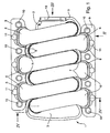
- FIGS. 2 has an inventive Suction system 1 an air distribution module 2, which has a modular structure is and from one according to FIGS. 2, 3, 4 upper one-piece Air distributor upper part module 3 and according to 2, 3, 4 lower one-piece air distributor lower module 4 exists.
- the air distributor upper module 3 and that Air distributor lower part module 4 each point outwards protruding, all-round collar or collar 5 on which the two modules 3 and 4 are connected are.
- each one-piece intake manifold module 6 connected or with the air distributor upper module 3 and thus connected to the air distribution module 2.
- Any of these Intake manifold module 6 is a cylinder, not shown Assigned to the internal combustion engine and used for air supply the associated combustion chamber. While the air distribution modules 6 at its one pipe end 7 with the air distribution module 2 are connected, they are with their other Pipe end 8 connected to a flange module 9, which at the Internal combustion engine is attachable. For this purpose points the flange module 9 corresponding mounting openings 10.
- the Suction system 1 configured for a 6-cylinder V engine, see above that accordingly two flange modules 9 are provided.
- the flange modules 9 each extend along one side of the air distribution module 2.
- the six intake manifold modules 6 are arranged side by side and alternating with the one or connected to the other flange module 9.
- the intake manifold modules 6 of each flange module 9 are each in an area facing the other flange module 9 of the air distributor module 2 to the air distributor module 2 connected, whereby adjacent intake manifold modules 6 above of the air distribution module 2 parallel to each other and to each other run along.
- FIGS. 1 to 3 is a particularly compact design for the suction system 1.
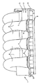
- receptacles 11 are left in which an injection valve 12 can be mounted, which is indicated in FIG. 4 is.
- the air distributor upper part module 3 is also at one Front of the suction system 1 equipped with a connection 13, with which the suction system 1 to an air supply Internal combustion engine is connectable.
- the through this air supply air supplied to the suction system 1 first penetrates into the air distribution module 2, is collected there and then distributed to the individual intake manifold modules 6, from where the air supplied finally into the combustion chambers of the internal combustion engine arrives.
- the suction system 1 according to the invention is produced preferably as follows:
- the intake manifold modules 6 are replaced by a suitable one Manufacturing processes, e.g. Blow molding or injection molding, manufactured. By producing them as separate modules it is possible to make the shape of the intake manifold modules 6 relative easy to vary, for example the pipe diameter, the radius of curvature and the tube length in this way to different configurations of the internal combustion engine be adjusted. Parallel to the manufacture of the intake manifold modules 6 can the air distributor upper module 3 and the air distributor lower module 4 separately, e.g. through a conventional Injection molding processes are made.
- a suitable one Manufacturing processes e.g. Blow molding or injection molding
- the intake manifold modules each assigned to a flange module 9 6 are then at least with their pipe ends 8 in an injection mold inserted and aligned if necessary. in the An injection molding process can then follow, in which the respective flange module 9 is formed. It is the respective flange 9 associated pipe end 8 of the intake manifold modules 6 designed so that it is in the spraying process on both sides, i.e. with respect to the intake manifold module 6 inside and outside, is bordered by the material of the flange module 9. In addition, the wall thickness of the intake manifold module expands 6 in this pipe end 8, so that there is a total highly effective anchoring of the intake manifold module 6 in the flange module 9 trains.
- the tube end 8 is thus at least form-fitting connected to the flange module 9.
- the Plastics of the two modules 6 and 9 in the connection area fused together in the manner of a welding process. The plastics are chosen to be compatible.
- the nested Sockets 7 and 14 can then be connected to one another, preferably a welding process is used to a most intimate, preferably cohesive or chemical connection between the intake manifold module 6 and the Form air distribution module 2.
- An adhesive connection can also be used or a shrink connection or a combination various connection techniques are trained.
- intake manifold modules 6 can be aligned Suction system components are carried out.
- the air distributor lower part module 4 can be equipped with a conventional friction welding process on the air distributor upper part module 3 can be connected. It is clear that the connection of the two modules 3 and 4 of the air distribution module 2 can be carried out here in advance, so that accordingly the complete air distribution module 2 with the intake manifold modules 6 is connected.
Landscapes
- Engineering & Computer Science (AREA)
- Mechanical Engineering (AREA)
- Chemical & Material Sciences (AREA)
- Combustion & Propulsion (AREA)
- General Engineering & Computer Science (AREA)
- Manufacturing & Machinery (AREA)
- Lubrication Details And Ventilation Of Internal Combustion Engines (AREA)
- Cylinder Crankcases Of Internal Combustion Engines (AREA)
- Injection Moulding Of Plastics Or The Like (AREA)
- Characterised By The Charging Evacuation (AREA)
Priority Applications (1)
| Application Number | Priority Date | Filing Date | Title |
|---|---|---|---|
| EP04003211A EP1422415B1 (de) | 1999-03-08 | 2000-03-02 | Sauganlage für eine Brennkraftmaschine |
Applications Claiming Priority (3)
| Application Number | Priority Date | Filing Date | Title |
|---|---|---|---|
| DE19909850 | 1999-03-08 | ||
| DE19909850A DE19909850A1 (de) | 1999-03-08 | 1999-03-08 | Sauganlage für eine Brennkraftmaschine |
| PCT/DE2000/000585 WO2000053919A1 (de) | 1999-03-08 | 2000-03-02 | Sauganlage für eine brennkraftmaschine |
Related Child Applications (2)
| Application Number | Title | Priority Date | Filing Date |
|---|---|---|---|
| EP04003211A Division EP1422415B1 (de) | 1999-03-08 | 2000-03-02 | Sauganlage für eine Brennkraftmaschine |
| EP04003211.2 Division-Into | 2004-02-12 |
Publications (2)
| Publication Number | Publication Date |
|---|---|
| EP1161626A1 EP1161626A1 (de) | 2001-12-12 |
| EP1161626B1 true EP1161626B1 (de) | 2004-10-13 |
Family
ID=7899906
Family Applications (2)
| Application Number | Title | Priority Date | Filing Date |
|---|---|---|---|
| EP04003211A Expired - Lifetime EP1422415B1 (de) | 1999-03-08 | 2000-03-02 | Sauganlage für eine Brennkraftmaschine |
| EP00915123A Expired - Lifetime EP1161626B1 (de) | 1999-03-08 | 2000-03-02 | Sauganlage für eine brennkraftmaschine |
Family Applications Before (1)
| Application Number | Title | Priority Date | Filing Date |
|---|---|---|---|
| EP04003211A Expired - Lifetime EP1422415B1 (de) | 1999-03-08 | 2000-03-02 | Sauganlage für eine Brennkraftmaschine |
Country Status (6)
| Country | Link |
|---|---|
| US (1) | US6581561B1 (enExample) |
| EP (2) | EP1422415B1 (enExample) |
| JP (1) | JP2002539359A (enExample) |
| DE (3) | DE19909850A1 (enExample) |
| ES (2) | ES2279238T3 (enExample) |
| WO (1) | WO2000053919A1 (enExample) |
Families Citing this family (15)
| Publication number | Priority date | Publication date | Assignee | Title |
|---|---|---|---|---|
| DE10051116A1 (de) * | 2000-10-14 | 2002-04-25 | Mann & Hummel Filter | Saugrohr für eine Brennkraftmaschine mit mindestens zwei verschweißten Schalen |
| WO2002040846A1 (en) * | 2000-11-17 | 2002-05-23 | Hitachi, Ltd. | Intake module, members of the module, and electronic controlled throttle device for internal combustion engine |
| DE10063568A1 (de) * | 2000-12-20 | 2002-07-04 | Mahle Gmbh | Kühlkanalkolben für einen Dieselmotor mit Direkteinspritzung mit einem Kolbendurchmesser von 100 mm |
| FR2819557B1 (fr) * | 2001-01-17 | 2003-09-19 | Mark Iv Systemes Moteurs Sa | Collecteur ou repartiteur d'admission pour moteur thermique et procede de fabrication |
| JP2006125227A (ja) * | 2004-10-27 | 2006-05-18 | Toyota Motor Corp | 合成樹脂製吸気マニホールドの溶着構造 |
| US7216620B1 (en) * | 2006-02-13 | 2007-05-15 | Mann & Hummel Gmbh | Engine lower intake manifold and method for making the same |
| US8181620B2 (en) * | 2008-08-11 | 2012-05-22 | Mark IV Systems Moteurs USA, Inc. | Modular intake manifold |
| US8074616B2 (en) * | 2008-08-11 | 2011-12-13 | Mark Iv Systemes Moteurs Usa, Inc. | Engine air intake manifold having a shell |
| DE102010019752A1 (de) | 2010-05-07 | 2011-11-10 | Daimler Ag | Verbrennungskraftmaschine |
| US8751800B1 (en) | 2011-12-12 | 2014-06-10 | Google Inc. | DRM provider interoperability |
| JP5949809B2 (ja) * | 2014-02-28 | 2016-07-13 | トヨタ自動車株式会社 | 吸気管、及び吸気管の成形方法 |
| US10208721B2 (en) | 2017-03-15 | 2019-02-19 | Brp-Rotax Gmbh & Co. Kg | Method and system for manufacturing a family of intake manifolds for a family of internal combustion engines |
| USD893551S1 (en) * | 2019-05-19 | 2020-08-18 | Deepmotor, Inc. | Intake manifold |
| USD907665S1 (en) * | 2019-05-19 | 2021-01-12 | Deepmotor, Inc. | Intake manifold |
| USD962291S1 (en) | 2021-08-06 | 2022-08-30 | Deepmotor Inc | Intake manifold |
Family Cites Families (21)
| Publication number | Priority date | Publication date | Assignee | Title |
|---|---|---|---|---|
| US4649871A (en) * | 1984-03-22 | 1987-03-17 | Mazda Motor Corporation | Intake system for V-type engine |
| US4643137A (en) * | 1984-04-09 | 1987-02-17 | Mazda Motor Corporation | Engine construction |
| DE3437102A1 (de) * | 1984-10-10 | 1986-04-10 | Audi AG, 8070 Ingolstadt | Saugrohranlage fuer mehrzylinder-brennkraftmaschinen |
| US4829944A (en) * | 1986-06-25 | 1989-05-16 | Showa Aluminum Corporation | Intake manifold and process for producing same |
| JP3384492B2 (ja) * | 1992-02-05 | 2003-03-10 | 富士重工業株式会社 | 樹脂製吸気管の製造方法 |
| DE4212807A1 (de) * | 1992-04-16 | 1993-10-21 | Bayerische Motoren Werke Ag | Kunststoffsauganlage für Brennkraftmaschinen |
| CA2073935C (en) * | 1992-05-01 | 2000-10-17 | Changize Sadr | Method for molding manifold for automotive vehicle |
| DE4216255A1 (de) * | 1992-05-16 | 1993-11-18 | Mann & Hummel Filter | Ansaugrohr und Verfahren zu dessen Herstellung |
| US5273010A (en) * | 1992-08-28 | 1993-12-28 | General Motors Corporation | Intake manifold |
| FR2697293B1 (fr) * | 1992-10-26 | 1994-11-10 | Solex | Dispositif d'alimentation à tubulure intégrée. |
| JPH07197865A (ja) * | 1993-12-29 | 1995-08-01 | Yamaha Motor Co Ltd | V型多気筒エンジンの吸気装置 |
| US5636605A (en) * | 1994-06-22 | 1997-06-10 | Toyota Jidosha K.K. | Composite intake manifold for an internal combustion engine |
| JP3352572B2 (ja) * | 1995-09-07 | 2002-12-03 | ダイハツ工業株式会社 | 多気筒内燃機関における吸気装置 |
| US5651338A (en) * | 1996-03-26 | 1997-07-29 | Pacheco; Allan A. | Adjustable induction manifold system |
| JPH09291859A (ja) * | 1996-04-30 | 1997-11-11 | Suzuki Motor Corp | 船外機の吸気装置 |
| US5715782A (en) * | 1996-08-29 | 1998-02-10 | Genral Motors Corporation | Composite molded butterfly valve for an internal combustion engine |
| DE19647184A1 (de) * | 1996-11-14 | 1998-05-20 | Mann & Hummel Filter | Ansaugmodul für einen Verbrennungsmotor |
| JPH1162741A (ja) * | 1997-08-08 | 1999-03-05 | Suzuki Motor Corp | エンジンの吸気マニホルド |
| KR100331454B1 (ko) | 1998-09-01 | 2002-04-09 | 신구 이이치 | 다기통 내연기관에 있어서의 관성과급식 흡기매니폴드의 구조및 이 흡기매니폴드에 있어서의 브랜치파이프의 접합방법 |
| JP3394192B2 (ja) | 1998-09-01 | 2003-04-07 | ジー・ピー・ダイキョー株式会社 | 合成樹脂製インテークマニホールド及びその製造方法 |
| JP2000199461A (ja) * | 1998-12-29 | 2000-07-18 | Suzuki Motor Corp | 内燃機関の吸気装置 |
-
1999
- 1999-03-08 DE DE19909850A patent/DE19909850A1/de not_active Withdrawn
-
2000
- 2000-03-02 DE DE2000508232 patent/DE50008232D1/de not_active Expired - Lifetime
- 2000-03-02 US US09/914,972 patent/US6581561B1/en not_active Expired - Fee Related
- 2000-03-02 EP EP04003211A patent/EP1422415B1/de not_active Expired - Lifetime
- 2000-03-02 DE DE50013911T patent/DE50013911D1/de not_active Expired - Lifetime
- 2000-03-02 EP EP00915123A patent/EP1161626B1/de not_active Expired - Lifetime
- 2000-03-02 JP JP2000604121A patent/JP2002539359A/ja active Pending
- 2000-03-02 WO PCT/DE2000/000585 patent/WO2000053919A1/de not_active Ceased
- 2000-03-02 ES ES04003211T patent/ES2279238T3/es not_active Expired - Lifetime
- 2000-03-02 ES ES00915123T patent/ES2228487T3/es not_active Expired - Lifetime
Also Published As
| Publication number | Publication date |
|---|---|
| DE50013911D1 (de) | 2007-02-08 |
| EP1422415A3 (de) | 2005-05-18 |
| US6581561B1 (en) | 2003-06-24 |
| EP1422415A2 (de) | 2004-05-26 |
| JP2002539359A (ja) | 2002-11-19 |
| ES2279238T3 (es) | 2007-08-16 |
| DE50008232D1 (de) | 2004-11-18 |
| ES2228487T3 (es) | 2005-04-16 |
| DE19909850A1 (de) | 2000-09-14 |
| EP1161626A1 (de) | 2001-12-12 |
| EP1422415B1 (de) | 2006-12-27 |
| WO2000053919A1 (de) | 2000-09-14 |
Similar Documents
| Publication | Publication Date | Title |
|---|---|---|
| EP1161626B1 (de) | Sauganlage für eine brennkraftmaschine | |
| EP0489238B1 (de) | Ansaugverteiler für eine Brennkraftmaschine | |
| DE102004015926B4 (de) | Einlassverteiler aus Harz | |
| EP0640177B1 (de) | Ansaugrohr und verfahren zu dessen herstellung | |
| EP2399019B1 (de) | Wasserabscheider, insbesondere für kraftstoffzuführsysteme von brennkraftmaschinen in kraftfahrzeugen | |
| EP0953101B1 (de) | Ansaugeinrichtung aus thermoplastischem kunststoff | |
| EP0835374B1 (de) | Ansaugeinrichtung aus thermoplastischem kunststoff | |
| WO1999002327A1 (de) | Kunststoffbehälter und verfahren zu seiner herstellung | |
| EP0891486B1 (de) | Ansaugsystem für einen verbrennungsmotor | |
| DE102016012534A1 (de) | System und Verfahren zum Herstellen von Bauteilen aus faserverstärktem Kunststoff | |
| EP2000659B1 (de) | Ansaugsystem | |
| EP1270917B1 (de) | Zwischenflanschsystem für eine direkteinspritzende Brennkraftmaschine | |
| EP1117924A1 (de) | Kraftstoffhochdruckspeicher | |
| EP1277947B1 (de) | Befestigungsvorrichtung für einen Ansaugverteiler | |
| DE19753390A1 (de) | Stapelförmig angeordneter, schneckenförmiger Krümmer | |
| EP0709557B1 (de) | Vorrichtung zum Einblasen von Luft in ein Abgasrohr | |
| DE60002018T2 (de) | Zentrale Luftzufuhr für luftunterstütztes Brennstoffeinspritzventil | |
| EP1279804B1 (de) | Luftansaugkanalsystem für Brennkraftmaschinen | |
| DE4310187C2 (de) | Rohrschelle | |
| DE10251406B4 (de) | Saugmodul für einen Verbrennungsmotor | |
| WO2002101226A1 (de) | Ansaugkrümmer, inbesondere für brennkraftmaschinen | |
| DE9314371U1 (de) | Rohrzusammenführung | |
| DE102004035648B4 (de) | Kraftstoffzuführung für einen Brennkraftmotor mit Direkteinspritzung | |
| WO2007003442A1 (de) | Ansaugsystem einer brennkraftmaschine | |
| DE4240470A1 (en) | IC engine with improved carburation - has heated insert body with flow-parallel channels, behind each injection valve set at angle to flow direction of valve |
Legal Events
| Date | Code | Title | Description |
|---|---|---|---|
| PUAI | Public reference made under article 153(3) epc to a published international application that has entered the european phase |
Free format text: ORIGINAL CODE: 0009012 |
|
| 17P | Request for examination filed |
Effective date: 20010420 |
|
| AK | Designated contracting states |
Kind code of ref document: A1 Designated state(s): AT BE CH CY DE DK ES FI FR GB GR IE IT LI LU MC NL PT SE |
|
| RAP1 | Party data changed (applicant data changed or rights of an application transferred) |
Owner name: MAHLE FILTERSYSTEME GMBH Owner name: DR.ING. H.C. F. PORSCHE AKTIENGESELLSCHAFT |
|
| RIN1 | Information on inventor provided before grant (corrected) |
Inventor name: SCHNEIDER, HORST Inventor name: KACHLER, GUENTER Inventor name: STEHLIG, JUERGEN Inventor name: DIETERLE, FRANK Inventor name: DRESPLING, HANS-PETER Inventor name: BRODESSER, KAY Inventor name: JENSEN, HANS Inventor name: KELM, JOACHIM |
|
| 17Q | First examination report despatched |
Effective date: 20030422 |
|
| GRAP | Despatch of communication of intention to grant a patent |
Free format text: ORIGINAL CODE: EPIDOSNIGR1 |
|
| RBV | Designated contracting states (corrected) |
Designated state(s): DE ES FR GB |
|
| GRAS | Grant fee paid |
Free format text: ORIGINAL CODE: EPIDOSNIGR3 |
|
| GRAA | (expected) grant |
Free format text: ORIGINAL CODE: 0009210 |
|
| AK | Designated contracting states |
Kind code of ref document: B1 Designated state(s): DE ES FR GB |
|
| REG | Reference to a national code |
Ref country code: GB Ref legal event code: FG4D Free format text: NOT ENGLISH |
|
| REG | Reference to a national code |
Ref country code: IE Ref legal event code: FG4D Free format text: GERMAN |
|
| REF | Corresponds to: |
Ref document number: 50008232 Country of ref document: DE Date of ref document: 20041118 Kind code of ref document: P |
|
| REG | Reference to a national code |
Ref country code: ES Ref legal event code: FG2A Ref document number: 2228487 Country of ref document: ES Kind code of ref document: T3 |
|
| REG | Reference to a national code |
Ref country code: IE Ref legal event code: FD4D |
|
| PLBE | No opposition filed within time limit |
Free format text: ORIGINAL CODE: 0009261 |
|
| STAA | Information on the status of an ep patent application or granted ep patent |
Free format text: STATUS: NO OPPOSITION FILED WITHIN TIME LIMIT |
|
| ET | Fr: translation filed | ||
| 26N | No opposition filed |
Effective date: 20050714 |
|
| PGFP | Annual fee paid to national office [announced via postgrant information from national office to epo] |
Ref country code: ES Payment date: 20100308 Year of fee payment: 11 |
|
| PGFP | Annual fee paid to national office [announced via postgrant information from national office to epo] |
Ref country code: FR Payment date: 20110401 Year of fee payment: 12 |
|
| PGFP | Annual fee paid to national office [announced via postgrant information from national office to epo] |
Ref country code: GB Payment date: 20110321 Year of fee payment: 12 |
|
| GBPC | Gb: european patent ceased through non-payment of renewal fee |
Effective date: 20120302 |
|
| REG | Reference to a national code |
Ref country code: FR Ref legal event code: ST Effective date: 20121130 |
|
| PG25 | Lapsed in a contracting state [announced via postgrant information from national office to epo] |
Ref country code: FR Free format text: LAPSE BECAUSE OF NON-PAYMENT OF DUE FEES Effective date: 20120402 Ref country code: GB Free format text: LAPSE BECAUSE OF NON-PAYMENT OF DUE FEES Effective date: 20120302 |
|
| REG | Reference to a national code |
Ref country code: ES Ref legal event code: FD2A Effective date: 20131029 |
|
| PG25 | Lapsed in a contracting state [announced via postgrant information from national office to epo] |
Ref country code: ES Free format text: LAPSE BECAUSE OF NON-PAYMENT OF DUE FEES Effective date: 20110303 |
|
| PGFP | Annual fee paid to national office [announced via postgrant information from national office to epo] |
Ref country code: DE Payment date: 20160531 Year of fee payment: 17 |
|
| REG | Reference to a national code |
Ref country code: DE Ref legal event code: R119 Ref document number: 50008232 Country of ref document: DE |
|
| PG25 | Lapsed in a contracting state [announced via postgrant information from national office to epo] |
Ref country code: DE Free format text: LAPSE BECAUSE OF NON-PAYMENT OF DUE FEES Effective date: 20171003 |