EP1160633A1 - Replenisher mechanism for a development station of a reproduction apparatus - Google Patents
Replenisher mechanism for a development station of a reproduction apparatus Download PDFInfo
- Publication number
- EP1160633A1 EP1160633A1 EP01110047A EP01110047A EP1160633A1 EP 1160633 A1 EP1160633 A1 EP 1160633A1 EP 01110047 A EP01110047 A EP 01110047A EP 01110047 A EP01110047 A EP 01110047A EP 1160633 A1 EP1160633 A1 EP 1160633A1
- Authority
- EP
- European Patent Office
- Prior art keywords
- particulate material
- housing
- pivot rod
- paddle
- delivery tube
- Prior art date
- Legal status (The legal status is an assumption and is not a legal conclusion. Google has not performed a legal analysis and makes no representation as to the accuracy of the status listed.)
- Withdrawn
Links
- 230000007246 mechanism Effects 0.000 title claims abstract description 57
- 238000011161 development Methods 0.000 title description 14
- 239000011236 particulate material Substances 0.000 claims abstract description 95
- 239000012528 membrane Substances 0.000 claims abstract description 26
- 238000004891 communication Methods 0.000 claims abstract description 11
- 238000005054 agglomeration Methods 0.000 claims abstract description 7
- 230000002776 aggregation Effects 0.000 claims abstract description 7
- 238000004519 manufacturing process Methods 0.000 claims abstract description 5
- 239000002245 particle Substances 0.000 claims description 35
- 239000000463 material Substances 0.000 claims description 23
- 238000007906 compression Methods 0.000 claims description 5
- 230000006835 compression Effects 0.000 claims description 5
- 230000000712 assembly Effects 0.000 claims 3
- 238000000429 assembly Methods 0.000 claims 3
- 238000007789 sealing Methods 0.000 claims 2
- 230000009471 action Effects 0.000 description 3
- 230000015572 biosynthetic process Effects 0.000 description 2
- 230000000694 effects Effects 0.000 description 2
- 238000005516 engineering process Methods 0.000 description 2
- 229920000642 polymer Polymers 0.000 description 2
- 238000012546 transfer Methods 0.000 description 2
- 239000000853 adhesive Substances 0.000 description 1
- 230000001070 adhesive effect Effects 0.000 description 1
- 230000007423 decrease Effects 0.000 description 1
- 230000007547 defect Effects 0.000 description 1
- 230000006866 deterioration Effects 0.000 description 1
- 238000010586 diagram Methods 0.000 description 1
- 230000009977 dual effect Effects 0.000 description 1
- 230000005684 electric field Effects 0.000 description 1
- 238000009472 formulation Methods 0.000 description 1
- 230000001939 inductive effect Effects 0.000 description 1
- 239000002184 metal Substances 0.000 description 1
- 239000000203 mixture Substances 0.000 description 1
- 238000012986 modification Methods 0.000 description 1
- 230000004048 modification Effects 0.000 description 1
- 229920002379 silicone rubber Polymers 0.000 description 1
- 238000003756 stirring Methods 0.000 description 1
- 238000013519 translation Methods 0.000 description 1
Images

Classifications
-
- G—PHYSICS
- G03—PHOTOGRAPHY; CINEMATOGRAPHY; ANALOGOUS TECHNIQUES USING WAVES OTHER THAN OPTICAL WAVES; ELECTROGRAPHY; HOLOGRAPHY
- G03G—ELECTROGRAPHY; ELECTROPHOTOGRAPHY; MAGNETOGRAPHY
- G03G15/00—Apparatus for electrographic processes using a charge pattern
- G03G15/06—Apparatus for electrographic processes using a charge pattern for developing
- G03G15/08—Apparatus for electrographic processes using a charge pattern for developing using a solid developer, e.g. powder developer
- G03G15/0822—Arrangements for preparing, mixing, supplying or dispensing developer
- G03G15/0877—Arrangements for metering and dispensing developer from a developer cartridge into the development unit
-
- G—PHYSICS
- G03—PHOTOGRAPHY; CINEMATOGRAPHY; ANALOGOUS TECHNIQUES USING WAVES OTHER THAN OPTICAL WAVES; ELECTROGRAPHY; HOLOGRAPHY
- G03G—ELECTROGRAPHY; ELECTROPHOTOGRAPHY; MAGNETOGRAPHY
- G03G15/00—Apparatus for electrographic processes using a charge pattern
- G03G15/06—Apparatus for electrographic processes using a charge pattern for developing
- G03G15/08—Apparatus for electrographic processes using a charge pattern for developing using a solid developer, e.g. powder developer
- G03G15/0822—Arrangements for preparing, mixing, supplying or dispensing developer
- G03G15/0848—Arrangements for testing or measuring developer properties or quality, e.g. charge, size, flowability
- G03G15/0856—Detection or control means for the developer level
- G03G15/086—Detection or control means for the developer level the level being measured by electro-magnetic means
-
- G—PHYSICS
- G03—PHOTOGRAPHY; CINEMATOGRAPHY; ANALOGOUS TECHNIQUES USING WAVES OTHER THAN OPTICAL WAVES; ELECTROGRAPHY; HOLOGRAPHY
- G03G—ELECTROGRAPHY; ELECTROPHOTOGRAPHY; MAGNETOGRAPHY
- G03G2215/00—Apparatus for electrophotographic processes
- G03G2215/08—Details of powder developing device not concerning the development directly
- G03G2215/0888—Arrangements for detecting toner level or concentration in the developing device
Definitions
- This invention relates in general to a replenisher mechanism for a development station of a reproduction apparatus, and more particularly to an electrographic reproduction apparatus development station where the replenisher mechanism for resupplying of marking particle material to a reproduction apparatus development station prevents agglomeration of the particulate material.
- a latent image charge pattern is formed on a uniformly charged charge-retentive or photoconductive member having dielectric characteristics (hereinafter referred to as the dielectric support member).
- Pigmented marking particles are attracted to the latent image charge pattern to develop such image on the dielectric support member.
- a receiver member such as a sheet of paper, transparency or other medium, is then brought into contact with the dielectric support member, and an electric field applied to transfer the marking particle developed image to the receiver member from the dielectric support member. After transfer, the receiver member bearing the transferred image is transported away from the dielectric support member, and the image is fixed (fused) to the receiver member by heat and pressure to form a permanent reproduction thereon.
- Marking particle material is very cohesive which can readily agglomerate in hoppers to produce structures commonly referred to as stable ratholes and bridges. Such stable ratholes or bridges prevent uniform delivery of marking particles to the exit point from the hopper. This results in variations in concentration of the marking particles in the development station of the reproduction apparatus which can ultimately lead to image defects in the copies made by the reproduction apparatus. Marking particles also tends to stick to surfaces (even vertical surfaces) of the hopper making sensing the level of marking particles in the hopper difficult.
- the marking particle material can form agglomerates or flakes through either cohesive or adhesive forces. Marking particle agglomerates formed cohesively are classified as hard or soft, Hard agglomerates cannot be broken up by the action of development station mixing, while soft agglomerates can be so broken up. On the other hand, marking particle flakes are pieces of melted or softened marking particles that have adhered together and hardened. Both the agglomerates and the flakes can be transferred to the dielectric support member of the reproduction apparatus and result in the formation of unwanted (undesirable) artifacts, or spots of marking particles, on copies made by the reproduction apparatus that render the copies unacceptable.
- the marking particle material hoppers generally include level sensors to monitor the level of particulate material in the hopper so as to determine when the material has to be replenished.
- Level sensors may include piezoelectric, capacitive, or inductive proximity sensors.
- the internal mechanical mixing elements and/or additional mechanical wipers are used to clear marking particles away from level sensors for accurate level reading.
- these internal mechanical mechanisms whether being used to break up agglomerates or clear the level sensors, can in and of themselves cause flakes and agglomerates.
- An alternative to internal mechanical mixing elements for preventing particulate material from agglomerating involves the use of flexible walls for the particulate material-containing hopper.
- Such flexible wall technology has been used in other industries before for feeding large amounts of cohesive materials.
- These flexible wall hoppers generally have a paddle on either side thereof. The paddles pivot from their midpoints to flex the flexible walls in order to break up the ratholes and bridges.
- the flexible wall hoppers in common commercial use now appear to rely on large paddle actuations to insure good particulate material flow.
- paddle action is not suitable for use in marking particle material hoppers due to compression of the marking particles in the bottom part of the hopper. This would result in agglomerate and flake production.
- this invention is directed to an external device to actuate the flexible membrane of a flexible wall of a replenisher mechanism particulate material housing to substantially completely break up the bridging of marking particles in the housing.
- the replenisher mechanism includes a housing having a sensor for sensing the level of particulate material within the housing, pair of spaced end walls, and a pair of spaced side walls. At least a portion of the side walls are flexible.
- An interface provides flow communication of particulate material between a particulate material receptacle and the housing, and a delivery assembly provides flow communication of particulate material between the housing and a remote reservoir.
- At least one paddle assembly is operatively associated with at least one of the flexible side walls for moving such side wall in a manner to substantially prevent agglomeration and flake production in the particulate material within the housing.
- the paddle assembly includes a first pivot rod mounted in fixed spatial relation to the housing, a paddle supported on the first pivot rod, a second pivot rod carried by the paddle.
- a reciprocating actuator arm is connected to the second pivot rod to selectively move the paddle about the first pivot rod.
- a lever is pivotably mounted on the second pivot rod, whereby when the paddle is rotated about the first pivot rod by reciprocation of the actuator arm, the lever rotates about the second pivot rod providing movement of the flexible membrane adjacent to the first pivot rod causing the breaking of any particulate material bridges at that point.
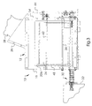
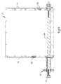
- the replenisher mechanism 10 includes a particulate material housing 12.
- the housing 12 has a pair of end walls 14, 16 spaced substantially parallel to one another. Connected to, and extending between, the end walls14, 16 are side walls 18, 20.
- the side walls 18, 20 are spaced from one another so as to be further apart at the top of the side walls and closer together at the bottom of the side walls.
- the replenisher mechanism 10 has an interface 26 mounted on the top of the housing 12 thereof.
- the interface 26 provides for connection to a particulate material receptacle 28 to enable selective flow communication for the particulate material between the receptacle and the housing 12 of the replenisher mechanism.
- the interface 26 has an angled entrance associated with the particulate material receptacle 28 to allow the particulate material to flow out of the receptacle reliably. Without this angled mounting, particulate material would most likely flow out of the receptacle very slowly and may form a bridge, thereby stopping particle flow all together.
- the housing 12 includes a particulate material delivery assembly 30 to provide selective flow communication for the particulate material between the housing 12 and a remote reservoir 32 (see FIG. 3), such as a development station of a typical electrographic reproduction apparatus (not shown). The delivery assembly 30 will be described more fully hereinbelow.
- the replenisher mechanism 10 utilizes flexible membranes on the angled sides of the particulate material housing 12, the membranes being alternately compressed with paddles which pivot from a point near their respective bottoms to push against the particulate material inside the housing.
- the moving particles act to fill in ratholes and collapse bridges that are formed during material delivery.
- the paddles are moved in tandem such that the particulate material is never being compressed between the paddles.
- This tandem actuation of the flexible membranes by two paddles provide movement of the particulate material inside the housing without mechanical intervention inside the housing, thus reducing the propensity of the particles to form agglomerates and flakes while insuring that material bridges and ratholes do not form.
- each of the side walls 18, 20 is respectively formed of a flexible membrane 18a, 20a.
- the important aspect of the formulation of the material of the flexible membrane is that it does not chemically (or otherwise) interact with the particulate material in the housing to negatively effect the particulate material or cause deterioration of the flexible membrane itself.
- the particulate material is polymer marking particles for developing electrostatic images in a reproduction apparatus.
- the material of the flexible membranes is made, for example, from silicon rubber that is known to be safe to use with electrostatic image development polymer marking particles.
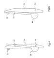
- the flexible membranes 18, 20 are periodically gently flexed respectively by paddles 22, 24.
- the flexible membranes are active across the whole length of the housing side walls 18, 20 allowing actuation even at the corners of the end walls 14, 16.
- the paddles 22, 24 are moved in tandem so that marking particle material in the housing 12 is never squeezed between the flexible membranes. This decreases the probability of formation of marking particle agglomerates.
- the paddles 22, 24 are respectively supported on pivot rods 34, 36.
- the pivot rods 34, 36 are, in turn, mounted in fixed spatial relation to the housing 12 of the replenisher mechanism 10.
- An actuator arm 38 is connected to pivot rods 40, 42 respectively associated with the paddles 22, 24.
- the arm 38 is reciprocated in any well known manner, by for example a cam mounted on a drive sprocket 44.
- the paddles 22, 24 move in tandem such that when one paddle is moving in a direction to flex the associated membrane in toward the housing 12, the other paddle is moving in a direction to enable the associated membrane to flex away from the housing.
- the replenisher mechanism 12 further includes levers 46, 48 to insure that particulate material cannot form a bridge near the pivot rods 34, 36 of the paddles.
- the levers 46, 48 are respectively pivotably mounted on the pivot rods 40, 42.
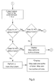
- sensing of the level of particulate material in the housing 12 of the replenisher mechanism 10 is accomplished by providing a plurality of level sensors 56, 58 (see FIGS. 1, 2, and 9).
- the level sensors 56, 58 are used to indicate when to add particulate material to the housing 12. This is important aspect of this invention in that the housing may hold over two receptacles of particulate material, and if material is added too soon an overflow may result.
- the level sensors 56, 58 are, for example, of the piezoelectric type with the sensing surface being a flat diaphragm.
- the level sensors 56, 58 are respectively located on the end wall 14, 16 of the housing 12. Each sensor is at a different elevation. The sensors must also be mounted flush or slightly protruded from the end walls so as not to allow a gap that material can become trapped in thus giving false indication of particulate material level.
- Multiple level sensors are used to give the a more accurate picture of how much particulate material is left in the housing of the replenisher mechanism 10.
- a signal may be generated indicating that one receptacle of particulate material may be supplied to the housing 12.
- the second (lower) of the sensors for example, sensor 56 on the end wall 14
- a signal may be generated indicating that more than one receptacle of particulate material may be supplied to the housing 12.
- FIG. 6 A logic flowchart for this dual mode of sensing of particulate material level is shown in FIG. 6.
- the replenisher mechanism 10 including two incorporating moveable membrane to gently agitate the bulk of marking particles in the hopper with the help of two paddles, negates the tendency of particulate material to form bridges and ratholes. Furthermore, it keeps the bulk of the material moving across the face of the level sensors, without the need for additional internal mechanical mechanisms, such as wipers or agitators, to keep the level sensors cleaned, insuring that the sensors are able to properly sense the presence of marking particles.
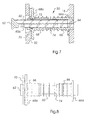
- the particulate material delivery assembly 30 of the replenisher mechanism 10 is best shown in FIGS. 7-9.
- the delivery assembly 30 includes a delivery tube 60 sealed at one end by a cap 62, and having an opening 60a adjacent to the end cap 62.
- the delivery tube 60 is adapted to accommodate a feed screw 64, which in operation advances particulate material from the housing 12 into the reservoir 32 through the tube.
- the delivery tube 60 supports an adapter member 66 and a slider member 68.
- the adapter member 66 has a flange 66a which is attached to the end wall 16 to properly locate the delivery tube 60 with respect to the feed screw 64.
- the slider member 68 has a flange 68a including a face seal 70.
- the slider member 68 has an internal diameter larger than the external diameter of the delivery tub 60 such that the slider member is free to slide on the delivery tube and move to accommodate any offset between the longitudinal axes of the delivery tube and the slider member.
- a seal 72 prevents particulate material leakage between the delivery tube 60 and the slider member 68.
- a compression spring 74 is located between the flanges 66a and 68a to urge the slider into engagement with the end cap 62 (see FIG. 8).
- the slider member 68 is positively urged into engagement with the end cap 62 by the compression spring 74. As such, the delivery tube 60 is sealed so that particulate material cannot leak out of the replenisher housing.
- the slider member 68 is urged by contact of the face seal 70 of the flange 68a with the reservoir 32, in a direction to uncover the opening 60a. This will provide particulate material flow communication via the delivery tube between the replenisher mechanism housing 12 and the reservoir 32.
- the relationship between the slider member 68 and the delivery tube 60 is such that any angular misalignment between the reservoir 32 of the development station and the replenisher mechanism 10 can be accommodated. Further, the delivery assembly 30 enables removal of the reservoir without moving the replenisher mechanism and insures that particulate material will not escape from the replenisher mechanism when the reservoir is removed.
- the flexible membranes and housing may be replaced by a flexible, v-shaped particulate material-containing bottle.
- the paddle actuation would then be applied to the bottle directly. This would require a small reservoir of particulate material to be kept below the bottle in a U-shaped channel which holds the material delivery auger to allow for bottle changes without interruption of particle delivery.
Landscapes
- Physics & Mathematics (AREA)
- General Physics & Mathematics (AREA)
- Filling Or Emptying Of Bunkers, Hoppers, And Tanks (AREA)
- Dry Development In Electrophotography (AREA)
Applications Claiming Priority (2)
| Application Number | Priority Date | Filing Date | Title |
|---|---|---|---|
| US09/574,036 US6298207B1 (en) | 2000-05-18 | 2000-05-18 | Replenisher mechanism for a development station of a reproduction apparatus |
| US574036 | 2000-05-18 |
Publications (1)
| Publication Number | Publication Date |
|---|---|
| EP1160633A1 true EP1160633A1 (en) | 2001-12-05 |
Family
ID=24294422
Family Applications (1)
| Application Number | Title | Priority Date | Filing Date |
|---|---|---|---|
| EP01110047A Withdrawn EP1160633A1 (en) | 2000-05-18 | 2001-04-27 | Replenisher mechanism for a development station of a reproduction apparatus |
Country Status (3)
| Country | Link |
|---|---|
| US (1) | US6298207B1 (enExample) |
| EP (1) | EP1160633A1 (enExample) |
| JP (1) | JP4541590B2 (enExample) |
Families Citing this family (1)
| Publication number | Priority date | Publication date | Assignee | Title |
|---|---|---|---|---|
| US6526236B1 (en) * | 2001-11-13 | 2003-02-25 | Nexpress Solutions Llc | Replenisher mechanism for a reproduction apparatus development station with continuous monitoring of remaining marking particle material |
Citations (4)
| Publication number | Priority date | Publication date | Assignee | Title |
|---|---|---|---|---|
| US4000833A (en) * | 1975-03-06 | 1977-01-04 | Itek Corporation | Toner dispensing apparatus |
| US4260073A (en) * | 1978-08-23 | 1981-04-07 | International Business Machines Corporation | Virgin toner and used toner supply apparatus and method |
| US4418643A (en) * | 1981-08-03 | 1983-12-06 | Ragen Precision Industries, Inc. | Feed hopper assembly for particulate material and printer |
| US5755358A (en) * | 1996-07-01 | 1998-05-26 | Xerox Corporation | Toner level detection system |
Family Cites Families (10)
| Publication number | Priority date | Publication date | Assignee | Title |
|---|---|---|---|---|
| CA1224241A (en) * | 1984-12-24 | 1987-07-14 | Sotos M. Theodoulou | Toner transfer apparatus |
| JPH0363678A (ja) * | 1989-08-01 | 1991-03-19 | Canon Inc | 粉粒体の補給容器 |
| JPH0433052U (enExample) * | 1990-07-12 | 1992-03-18 | ||
| JPH04152369A (ja) * | 1990-10-16 | 1992-05-26 | Canon Inc | 画像形成装置及びこの装置に着脱自在なプロセスカートリッジ |
| JPH0529059U (ja) * | 1991-09-27 | 1993-04-16 | 日立金属株式会社 | トナー補給装置 |
| JPH05204244A (ja) * | 1992-01-23 | 1993-08-13 | Ricoh Co Ltd | 画像形成装置 |
| EP0607528B1 (en) * | 1992-12-03 | 1997-04-16 | Eastman Kodak Company | Toner container and receiving apparatus therefor |
| JP3434085B2 (ja) * | 1995-06-30 | 2003-08-04 | 株式会社リコー | 現像剤供給装置 |
| JPH1063072A (ja) * | 1996-08-22 | 1998-03-06 | Tec Corp | 現像装置 |
| JP3739061B2 (ja) * | 1996-09-19 | 2006-01-25 | 株式会社リコー | トナー収納容器および画像形成装置 |
-
2000
- 2000-05-18 US US09/574,036 patent/US6298207B1/en not_active Expired - Fee Related
-
2001
- 2001-04-27 EP EP01110047A patent/EP1160633A1/en not_active Withdrawn
- 2001-05-18 JP JP2001149934A patent/JP4541590B2/ja not_active Expired - Fee Related
Patent Citations (4)
| Publication number | Priority date | Publication date | Assignee | Title |
|---|---|---|---|---|
| US4000833A (en) * | 1975-03-06 | 1977-01-04 | Itek Corporation | Toner dispensing apparatus |
| US4260073A (en) * | 1978-08-23 | 1981-04-07 | International Business Machines Corporation | Virgin toner and used toner supply apparatus and method |
| US4418643A (en) * | 1981-08-03 | 1983-12-06 | Ragen Precision Industries, Inc. | Feed hopper assembly for particulate material and printer |
| US5755358A (en) * | 1996-07-01 | 1998-05-26 | Xerox Corporation | Toner level detection system |
Also Published As
| Publication number | Publication date |
|---|---|
| JP2002014532A (ja) | 2002-01-18 |
| US6298207B1 (en) | 2001-10-02 |
| JP4541590B2 (ja) | 2010-09-08 |
Similar Documents
| Publication | Publication Date | Title |
|---|---|---|
| CA2018500C (en) | Toner metering apparatus | |
| TWI570528B (zh) | 具有用於碳粉位準感測的落下片之影像成形裝置的可置換單元 | |
| EP1560076B1 (en) | Toner container cartridge and refilling apparatus | |
| EP0368598B1 (en) | A toner recovery device | |
| JPH03269462A (ja) | トナーレベル検出装置 | |
| EP0666516B1 (en) | Development unit for electrophotographic copier | |
| US10571827B2 (en) | Developer replenishing device, developer device, and image forming device having a vibration plate that engages an agitation member | |
| JP2004029813A (ja) | 電子写真式印刷装置における排トナーのための攪拌および橋状物形成防止デバイス | |
| US8437680B2 (en) | Developer and image forming apparatus including the same | |
| US6298207B1 (en) | Replenisher mechanism for a development station of a reproduction apparatus | |
| CN101261472A (zh) | 显影装置及图像形成装置 | |
| US5797073A (en) | Toner container with biased closure | |
| CN100480883C (zh) | 显影装置和图像形成装置 | |
| EP0604191B1 (en) | Developing device and image forming apparatus | |
| JPS6122366A (ja) | 現像装置 | |
| US6640061B2 (en) | Sensing system for detecting a full condition within a waste developer system | |
| JPH0822187A (ja) | 画像形成装置 | |
| KR20050050459A (ko) | 현상카트리지 및 이를 구비한 전자사진방식 화상형성장치 | |
| US5755358A (en) | Toner level detection system | |
| JPH08211716A (ja) | 現像装置 | |
| JP2599994B2 (ja) | 現像剤の検知装置 | |
| CN105814494B (zh) | 成像装置 | |
| JP2534262Y2 (ja) | 現像剤搬送装置 | |
| JPH0223865B2 (enExample) | ||
| JPS6328437Y2 (enExample) |
Legal Events
| Date | Code | Title | Description |
|---|---|---|---|
| PUAI | Public reference made under article 153(3) epc to a published international application that has entered the european phase |
Free format text: ORIGINAL CODE: 0009012 |
|
| AK | Designated contracting states |
Kind code of ref document: A1 Designated state(s): BE CH DE FR GB LI NL Kind code of ref document: A1 Designated state(s): AT BE CH CY DE DK ES FI FR GB GR IE IT LI LU MC NL PT SE TR |
|
| AX | Request for extension of the european patent |
Free format text: AL;LT;LV;MK;RO;SI |
|
| 17P | Request for examination filed |
Effective date: 20011018 |
|
| AKX | Designation fees paid |
Free format text: BE CH DE FR GB LI NL |
|
| RAP1 | Party data changed (applicant data changed or rights of an application transferred) |
Owner name: EASTMAN KODAK COMPANY |
|
| STAA | Information on the status of an ep patent application or granted ep patent |
Free format text: STATUS: THE APPLICATION IS DEEMED TO BE WITHDRAWN |
|
| 18D | Application deemed to be withdrawn |
Effective date: 20060712 |