EP1160041A2 - Sägespänenabdichtungsvorrichtung - Google Patents
Sägespänenabdichtungsvorrichtung Download PDFInfo
- Publication number
- EP1160041A2 EP1160041A2 EP01850080A EP01850080A EP1160041A2 EP 1160041 A2 EP1160041 A2 EP 1160041A2 EP 01850080 A EP01850080 A EP 01850080A EP 01850080 A EP01850080 A EP 01850080A EP 1160041 A2 EP1160041 A2 EP 1160041A2
- Authority
- EP
- European Patent Office
- Prior art keywords
- transporter
- wood
- pieces
- sheet
- sheets
- Prior art date
- Legal status (The legal status is an assumption and is not a legal conclusion. Google has not performed a legal analysis and makes no representation as to the accuracy of the status listed.)
- Withdrawn
Links
Images

Classifications
-
- B—PERFORMING OPERATIONS; TRANSPORTING
- B23—MACHINE TOOLS; METAL-WORKING NOT OTHERWISE PROVIDED FOR
- B23Q—DETAILS, COMPONENTS, OR ACCESSORIES FOR MACHINE TOOLS, e.g. ARRANGEMENTS FOR COPYING OR CONTROLLING; MACHINE TOOLS IN GENERAL CHARACTERISED BY THE CONSTRUCTION OF PARTICULAR DETAILS OR COMPONENTS; COMBINATIONS OR ASSOCIATIONS OF METAL-WORKING MACHINES, NOT DIRECTED TO A PARTICULAR RESULT
- B23Q11/00—Accessories fitted to machine tools for keeping tools or parts of the machine in good working condition or for cooling work; Safety devices specially combined with or arranged in, or specially adapted for use in connection with, machine tools
- B23Q11/08—Protective coverings for parts of machine tools; Splash guards
- B23Q11/0866—Protective coverings for parts of machine tools; Splash guards using covering means adaptable to the workpieces, e.g. curtains or bristles
-
- B—PERFORMING OPERATIONS; TRANSPORTING
- B23—MACHINE TOOLS; METAL-WORKING NOT OTHERWISE PROVIDED FOR
- B23D—PLANING; SLOTTING; SHEARING; BROACHING; SAWING; FILING; SCRAPING; LIKE OPERATIONS FOR WORKING METAL BY REMOVING MATERIAL, NOT OTHERWISE PROVIDED FOR
- B23D59/00—Accessories specially designed for sawing machines or sawing devices
- B23D59/006—Accessories specially designed for sawing machines or sawing devices for removing or collecting chips
-
- B—PERFORMING OPERATIONS; TRANSPORTING
- B23—MACHINE TOOLS; METAL-WORKING NOT OTHERWISE PROVIDED FOR
- B23Q—DETAILS, COMPONENTS, OR ACCESSORIES FOR MACHINE TOOLS, e.g. ARRANGEMENTS FOR COPYING OR CONTROLLING; MACHINE TOOLS IN GENERAL CHARACTERISED BY THE CONSTRUCTION OF PARTICULAR DETAILS OR COMPONENTS; COMBINATIONS OR ASSOCIATIONS OF METAL-WORKING MACHINES, NOT DIRECTED TO A PARTICULAR RESULT
- B23Q11/00—Accessories fitted to machine tools for keeping tools or parts of the machine in good working condition or for cooling work; Safety devices specially combined with or arranged in, or specially adapted for use in connection with, machine tools
- B23Q11/08—Protective coverings for parts of machine tools; Splash guards
- B23Q11/0891—Protective coverings for parts of machine tools; Splash guards arranged between the working area and the operator
Definitions
- the present invention concerns a device in sawmills for separating two areas as described in the preamble to Claim 1.
- Pieces of wood, transported transversely on transporters, are cut in, for example, trimming saws and raw sorting plants at sawmills.
- the cutting process which is performed with cutting equipment of various models with one or more crosscutting saws, results in sawdust being spread in the surrounding areas. This impacts negatively on the environment and contaminates machinery.
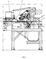
- FIG. 1 illustrates examples of two versions of the invention built into a cutting unit stationed at a sawmill
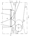
- Fig. 2 illustrates one of the versions of the invention applied downward from the cross-cutting saws
- Fig. 3 illustrates another version of the invention located forward from the cross-cutting saw.
- a cutting unit is illustrated in Fig. 1, through which pieces of wood 1 are transported transversely on a multiple section transporter in the cutting unit, generally designated 2.
- 6 designates pushers mounted on the transporter for moving the pieces of wood 1.
- Concerning the cutting station reference is made in this conjunction to Swedish patent application 9900044-0, whereby a more detailed description of the illustrated cutting unit is not necessary here.
- 3 designates adjacent mounted crosscutting saws, from which the majority of sawdust is collected in a sawdust channel 4 in the transporter.
- Figs. 1 and 2 illustrate a version of the invention in the form of a U-shaped sheet 5, which is suspended across the transporter 2.
- the sheet 5 has buckles or channels 7 along its two edges in which carrying and stiffening bodies, such as continuous flat irons 8, are inserted and suspended from e.g. a detachable cartridge 9, supported from a frame 11 attached to the cutting unit stand 10.
- the sag or bulge 12 of the U-shaped sheet 5 drops so low that it will reach the transporter 2 and between chains of applied cover plates 13 of known type and consequently also the pieces of wood 1 on the transporter 2. During transport, these pieces will consequently be pulled under the sheet 5, which, due to its form, will be in continuous contact with the pieces of wood 1 passing beneath.
- Figs. 1 and 3 illustrate another version of the invention located forward of the crosscutting saws 3.
- the invention illustrated here comprises two pieces of continuous, U-shaped sheet 5' stretched across the transporter 2.
- the design of these adjacent sheets 5' is the same as the single sheet 5 as illustrated in Fig.2.
- hoops 8 Into the buckles or channels 7 of the sheets are inserted hoops 8, which are inserted and suspended from, for example, a detachable cartridge 9 attached to the cutting unit's sawdust channel 4.
- a piece of wood 1 is placed under the existing downward sheet 5', the bulge 12 of which will drag against the piece of wood on its way past the sheet without the sheet lifting from the piece of wood.
- the aforementioned cover plates are also present at this location but have not been illustrated.
- the location of, for example, the U-shaped sheets 5' in relation to the cross-cut saws 3 is such that the sheets 5' will seal against a piece of wood 1 while a preceding piece of wood is being cut, thereby achieving optimum sealing effect from the sheets both during and in between cutting operations.
- the sheets 5 and 5' respectively can easily be attached and detached using a suitably designed cartridge and the flat irons 8 inserted in buckles or channels 7.
- the sheets will follow the motion of the pieces of wood in a pliant manner and will not be thrown up, as are conventional types of seal when speed is increased to, for example, a rate of 160. It is to be implied that the sealing effect can be improved by arranging more than two consecutive sealing sheets. In certain cases, it may be suitable to divide the sealing sheet hanging across the transporter into several pieces.
Landscapes
- Engineering & Computer Science (AREA)
- Mechanical Engineering (AREA)
- Dry Formation Of Fiberboard And The Like (AREA)
- Fish Paste Products (AREA)
- Debarking, Splitting, And Disintegration Of Timber (AREA)
- Attitude Control For Articles On Conveyors (AREA)
Applications Claiming Priority (2)
| Application Number | Priority Date | Filing Date | Title |
|---|---|---|---|
| SE0001654 | 2000-05-05 | ||
| SE0001654A SE0001654L (sv) | 2000-05-05 | 2000-05-05 | Anordning vid sågverk för avskiljning av två områden från varandra |
Publications (2)
| Publication Number | Publication Date |
|---|---|
| EP1160041A2 true EP1160041A2 (de) | 2001-12-05 |
| EP1160041A3 EP1160041A3 (de) | 2003-11-19 |
Family
ID=20279553
Family Applications (1)
| Application Number | Title | Priority Date | Filing Date |
|---|---|---|---|
| EP01850080A Withdrawn EP1160041A3 (de) | 2000-05-05 | 2001-05-02 | Sägespänenabdichtungsvorrichtung |
Country Status (2)
| Country | Link |
|---|---|
| EP (1) | EP1160041A3 (de) |
| SE (1) | SE0001654L (de) |
Cited By (1)
| Publication number | Priority date | Publication date | Assignee | Title |
|---|---|---|---|---|
| NL2005941C2 (nl) * | 2010-12-30 | 2012-07-03 | Fico Bv | Afdichting van een zaagmachine voor het separeren van elektronische componenten en zaagmachine voorzien van een dergelijke afdichting. |
Family Cites Families (5)
| Publication number | Priority date | Publication date | Assignee | Title |
|---|---|---|---|---|
| FR1587214A (de) * | 1967-11-09 | 1970-03-13 | ||
| DE3200314A1 (de) * | 1982-01-08 | 1983-07-21 | Klaus 3500 Kassel Sichelschmidt | "schutzvorrichtung fuer rotierend angetriebene, spanabhebende werkzeuge" |
| DE3322013A1 (de) * | 1983-01-28 | 1984-08-02 | VEB Bau Dessau, DDR 4502 Dessau | Einrichtung zum entfernen von emissionen an werkzeugmaschinen |
| CA2185466C (en) * | 1996-09-12 | 1997-09-30 | Michel St-Pierre | Saw trimmer and method for trimming lumber pieces |
| SE511984C2 (sv) * | 1999-01-11 | 2000-01-10 | Renholmens Mek Verkstad Ab | Förfarande och anordning för kapning av virkesstycken |
-
2000
- 2000-05-05 SE SE0001654A patent/SE0001654L/ unknown
-
2001
- 2001-05-02 EP EP01850080A patent/EP1160041A3/de not_active Withdrawn
Cited By (3)
| Publication number | Priority date | Publication date | Assignee | Title |
|---|---|---|---|---|
| NL2005941C2 (nl) * | 2010-12-30 | 2012-07-03 | Fico Bv | Afdichting van een zaagmachine voor het separeren van elektronische componenten en zaagmachine voorzien van een dergelijke afdichting. |
| WO2012091559A1 (en) * | 2010-12-30 | 2012-07-05 | Fico B.V. | Seal for a sawing machine for separating electronic components and sawing machine provided with such a seal |
| US9644748B2 (en) | 2010-12-30 | 2017-05-09 | Besi Netherlands B.V. | Seal for a sawing machine for separating electronic components and sawing machine provided with such a seal |
Also Published As
| Publication number | Publication date |
|---|---|
| EP1160041A3 (de) | 2003-11-19 |
| SE0001654D0 (sv) | 2000-05-05 |
| SE514583C2 (sv) | 2001-03-19 |
| SE0001654L (sv) | 2001-03-19 |
Similar Documents
| Publication | Publication Date | Title |
|---|---|---|
| JPS6296239A (ja) | シ−ト素材を給送するコンベア式の真空テ−ブル | |
| DE69426339D1 (de) | Gerät zum Abdecken von Leitungen mit rotiernder Zuführvorrichtung | |
| EP1537966A3 (de) | Vorrichtung zum Schneiden von Brotlaiben sowie von anderen Backwaren | |
| DE3872043D1 (de) | Abdichtungssystem an einem foerderergestuetzten vakuumtisch fuer eine schneidvorrichtung. | |
| US20110083538A1 (en) | Band saw | |
| IT1294630B1 (it) | Macchina automatica elettronica taglia/spacca legna | |
| EP1160041A2 (de) | Sägespänenabdichtungsvorrichtung | |
| IT1228658B (it) | Dispositivo per la sezionatura ed l'accatastamento di rivette in legno. | |
| SE430233B (sv) | Tetningsanordning och forfarande for framstellning av en tetningsanordning vid en kedjesag avsedd for sagning av harda material sasom betong | |
| US3262475A (en) | Wood saws with holes for disposing of the saw dust | |
| KR102147137B1 (ko) | 두개의 띠톱을 이용한 왕복 절단형 띠톱 기계 | |
| ES2186392T3 (es) | Proceso para la subdivision de una cinta o cordon largo de un producto de goma en porciones individuales y dispositivo para llevar a cabo dicho proceso. | |
| GB2011773A (en) | Apparatus for Harvesting Mushrooms Cultivated on a Flat Bed | |
| EP1129831A3 (de) | Hochgeschwindigkeitssägekette | |
| SE8307213D0 (sv) | Sagmaskin | |
| ATE318235T1 (de) | Vorrichtung zum binden von palettierten produkten | |
| EP1260328A3 (de) | Trennmaschine | |
| WO2004011353A3 (fr) | Dispositif pour conditionner des bandes continues de materiau telles que les lisieres generees sur des unites de thermoformage | |
| ATE48063T1 (de) | Futteraufbereitungsmaschine. | |
| CN210213016U (zh) | 一种袋装物料划包机构 | |
| DE602004024120D1 (de) | Anordnung in verbindung mit einer querschneidesäge einer erntemaschine | |
| EP0095613A3 (de) | Maschine zum Zerschneiden und Wiedergewinnen der Rückstände beim Fällen von Bäumen | |
| US136216A (en) | Improvement in sawing-machines | |
| SU1184670A1 (ru) | Многопильна раскр жевочна установка | |
| JPS5845842Y2 (ja) | ツインバンドソ−製材機に於ける木材搬送装置 |
Legal Events
| Date | Code | Title | Description |
|---|---|---|---|
| PUAI | Public reference made under article 153(3) epc to a published international application that has entered the european phase |
Free format text: ORIGINAL CODE: 0009012 |
|
| AK | Designated contracting states |
Kind code of ref document: A2 Designated state(s): AT BE CH CY DE DK ES FI FR GB GR IE IT LI LU MC NL PT SE TR |
|
| AX | Request for extension of the european patent |
Free format text: AL;LT PAYMENT 20010502;LV PAYMENT 20010502;MK;RO;SI |
|
| PUAL | Search report despatched |
Free format text: ORIGINAL CODE: 0009013 |
|
| AK | Designated contracting states |
Kind code of ref document: A3 Designated state(s): AT BE CH CY DE DK ES FI FR GB GR IE IT LI LU MC NL PT SE TR |
|
| AX | Request for extension of the european patent |
Extension state: AL LT LV MK RO SI |
|
| RIC1 | Information provided on ipc code assigned before grant |
Ipc: 7B 23Q 11/08 B Ipc: 7B 23D 59/00 A |
|
| 17P | Request for examination filed |
Effective date: 20031212 |
|
| GRAP | Despatch of communication of intention to grant a patent |
Free format text: ORIGINAL CODE: EPIDOSNIGR1 |
|
| AKX | Designation fees paid |
Designated state(s): AT DE FI |
|
| AXX | Extension fees paid |
Extension state: LV Payment date: 20010502 Extension state: LT Payment date: 20010502 |
|
| STAA | Information on the status of an ep patent application or granted ep patent |
Free format text: STATUS: THE APPLICATION IS DEEMED TO BE WITHDRAWN |
|
| 18D | Application deemed to be withdrawn |
Effective date: 20040904 |