EP1159866A1 - Mähgerät mit zwei Mähköpfen - Google Patents
Mähgerät mit zwei Mähköpfen Download PDFInfo
- Publication number
- EP1159866A1 EP1159866A1 EP01110996A EP01110996A EP1159866A1 EP 1159866 A1 EP1159866 A1 EP 1159866A1 EP 01110996 A EP01110996 A EP 01110996A EP 01110996 A EP01110996 A EP 01110996A EP 1159866 A1 EP1159866 A1 EP 1159866A1
- Authority
- EP
- European Patent Office
- Prior art keywords
- mowing head
- mowing
- head
- working
- mower according
- Prior art date
- Legal status (The legal status is an assumption and is not a legal conclusion. Google has not performed a legal analysis and makes no representation as to the accuracy of the status listed.)
- Granted
Links
Images


Classifications
-
- A—HUMAN NECESSITIES
- A01—AGRICULTURE; FORESTRY; ANIMAL HUSBANDRY; HUNTING; TRAPPING; FISHING
- A01D—HARVESTING; MOWING
- A01D34/00—Mowers; Mowing apparatus of harvesters
- A01D34/835—Mowers; Mowing apparatus of harvesters specially adapted for particular purposes
- A01D34/86—Mowers; Mowing apparatus of harvesters specially adapted for particular purposes for use on sloping ground, e.g. on embankments or in ditches
- A01D34/866—Mounting means
Definitions
- the invention relates to a verge tool, as it is with different Working heads, for example mowing heads, to carry out different Margin work, can be equipped.
- Edge trim tools of this type in the following for reasons of simplification in principle called verge mowers are on work vehicles that in particular have a loading area arranged behind the driver's cab, arranged and work in the working position offset to the side of the work vehicle, so that this can drive along the road or path while the verge next to the road is worked or mowed.
- the aim is to mow the Edge strip can be done with only one operator, that is at the same time Work vehicle drives and the additional control of the mower that is still necessary can make at the same time. This is only possible if these are additional Control measures are limited to the lowest possible level or Control of the mower is carried out as fully automatically as possible, since only then high Driving speeds during work and thus high work performance are achievable.
- a typical problem is the mowing of verges from streets in which Distance the road boundary posts are arranged.
- edge trim mowers with two mowing heads are already available known that offset laterally and in the direction of travel to each other simultaneously both areas, i.e. inside and outside the road boundary posts, mow in a single operation.
- a tool is from the company Gerhard Dücker GmbH & Co. KG, Stadtlohn, is known. It is also on a front frame, on the one hand, one in the front working position, closest to the street First mowing head working on the edge and one behind, but laterally There is a second mower head working overlapping on the outside, each are arranged via separate extension arms, which are attached to the front frame.
- the width range between the edge of the carriageway and the roadside posts is generally less than the width range to be mowed outside of the Perimeter post.
- the vegetation is easier to mow there because it is in usually only consists of grass or weeds, while outdoors too Undergrowth and obstacles made of solid material. Because of this, and because the mowing head that works further inside is also used under guardrails on the one hand, the inner mowing head has a low housing height necessary and on the other hand because of the mower to be accommodated in it smaller diameter also possible.
- the mower head which works further inside, is generally less than the outer cutter head.
- this internal cutter head is used instead of the usual flywheel shaft or mower shaft, a mowing element chosen, which enables a small and light design of this mowing head.
- a mowing element chosen, which enables a small and light design of this mowing head.
- one with in particular individual knives is used as the mowing element equipped and in particular very fast-running cutter shaft selected only small diameter - in the direction of the mowing shaft and thus transverse to Considered the direction of travel - and thus also has a small housing and low overall weight enables.
- the outer mowing head is due to its larger mowing width and the larger Distance to the road and thus other vehicles - which is a smaller one
- the boom arm of the outer cutter head is transversely displaceable on the Offset rail arranged to the weight loads by the two mowing heads not to let the vehicle attack on the same side.
- the Boom arm for the outer mowing head primarily in the side strip facing away from usually left or middle, be positioned and in the transport position, i.e. with the outer mowing head placed on the loading area, positioned in the middle of the offset rail to improve the driver's visibility become.
- the sequence control described above i.e. controlling the second and each further Cutter head relative to the first cutter head, so that the driver only the first Mowing head with regard to the lateral distance to the vehicle and if necessary
- the altitude and incline also control the possibility of switching separate control of the individual mowing heads with individual control elements (Joystick) is also given when not only two but even three separate mowing heads are available:
- the third cutter head is also on a separate one Cantilever arm arranged and usually work furthest outside, so that this increases the overall working width of the device.
- the outermost The mowing head is usually identical to the middle mowing head, and the cantilever arms of these mowing heads are very similar or even identical, except for the greater length of the boom arm parts on the third and furthest outside mowing head.
- the third mowing head is not in the front area of the base vehicle, but in the rear area, either on the loading area or behind whose loading area, for example on a rear rail, arranged, and thereby preferably attached to a sliding base which is in the transverse direction along a Rear offset rail is slidable.
- this serves to help shift weight during work reasonably even utilization of the vehicle reach, and is especially for the storage of this third mowing head in the Transport position necessary:
- This third mowing head is above or on the with the boom arm folded Load area stored in the longitudinal direction, in the side area next to the Cantilever arm, for this purpose from the longitudinally extending Center position slightly off-center, i.e. away from the mower head to evenly distribute the weight on the loading area.
- the second Mower head at a height distance above the loading area in the transport position left in which its cantilever arm on one across the front end the loading area, i.e. over the rear end of the driver's cab or over the Driver's cab running, is put down.
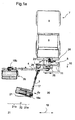
- a work vehicle 7 is used as the carrier vehicle, which has a loading area 5 behind the driver's cabin 6.
- a Front frame 8 mounted on the two extension arms 3, 4 for the inner mowing head 2a or outer cutter head 2b are attached.
- the cantilever arm 3 for the inner cutter head 2a is firmly on the outermost Point 23 of the right side of the offset rail 11, which is the front end of the Front frame 8 forms, immovably attached along the offset rail 11. A change from the left to the right side of the offset rail 11 is however generally possible.
- the cantilever arm 3 is the fastening point on the front frame 8 both horizontally and vertically pivotable, has a central parallelogram-like or telescopic Section 17 on, and sufficient articulation points around the free end of the cantilever arm 3 attached inner cutter head 2a in the desired position to bring and hold the angular position with respect to the work vehicle 7.
- the Actuation of the cantilever arm and preferably also the mowing shaft Working heads are preferably hydraulic.
- the cantilever arm is 4 for the outer cutter head 2b along the offset rail 11 of the front frame 8 movable in the transverse direction 19.
- the working heads 2a, 2b are in the working position positioned so that the outer working head 2b is still in front of the Front frame 8, but at least in front of the driver's cab 6 of the work vehicle 7 is located, preferably at a right angle to the direction of travel 10 cantilever arm 4 running in supervision.
- the lateral offset of the outer cutter head 2b is set so that the Work vehicle 7 pointing, usually left outer edge of the mowing head 2b can drive past just outside the street boundary posts 22, if the work vehicle 7 is exactly on the edge of the road 20 or in a predetermined Distance to the edge of the road 20 is controlled.
- the inner cutter head 2a is set so that it is in the longitudinal direction is located in front of the outer cutter head 2b, the lateral offset so is set that the area between the edge of the road 20 and the inner, ie left, edge of the mowing area of the outer mowing head 2b completely is covered.
- the front mowing head 2a is preferably slightly oblique, that is not set exactly at right angles to the direction of travel 10, so that the outside end lying slightly further back in the direction of travel than the inner end End at which the boom arm 3 engages.
- the inner cutter head 2a has via the known feeler bar 12, which is in front of the front edge of the mowing head is pivotally attached near the inner left end, and reaching one Obstacle, for example the edge of a back in the direction of travel Limiting post 22, registered.
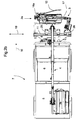
- Figures 2a and 2b show the mower 1 in the for the present invention important transport position: the mounting shoe 26, with the help of the Boom 3 of the inner mowing head 2a is fixedly attached to the offset rail 11, is still in the rightmost position on the offset rail 11.
- the sliding shoe 25 on which the cantilever arm 4 for the outer Mowing head 2b is fixed, is preferably in the transport position in the middle position with respect to the offset rail 11 and thus the vehicle 7, while in the mowing position of Figures 1a and 1b except that shown there Middle position also positioning on the other, i.e. from the fastening shoe 23 opposite left end of the offset rail for the purpose of better Weight distribution is possible if the length of the cantilever arm 4 allows.
- the outer cutter head 2b is on the Loading area 5, which is usually arranged behind the cab 6 of the vehicle 7 is preferably stored with the alignment of the mowing shaft of this mowing head 2b in the direction of travel 10 and in the middle or on one side of the loading area. The remaining areas then remain as freely available loading space.
- the cantilever arm 4 also preferably extends counter to the direction of travel 10 running across the center of the cab from the front Front frame 8 to the mowing head 2b placed on the rear loading area 5 the middle of which the boom 4 attacks.
- the inner cutter head 2a is on a holder provided for this purpose Part of the front frame is as close as possible in front of the front frame 8 held. A certain minimum distance is required, which is determined by the front Cantilever of the sliding shoe 25 conditionally in front of the front rail 11 becomes.
- the cantilever arm 3 is 17 with respect to its central section retracted, and extends partially in the direction of travel 10 forward and the other part also transversely to the direction of travel in front of the front rail 11 and thus parallel above the mowing head 2a, which extends with its Mowing shaft is also arranged transversely, ie at right angles 10, and its Articulation point 18a opposite the free front end of the cantilever arm 3 itself located at the left end of the mowing head.
- this is the weight of the two cutter heads 2a, 2b distributed to the front and rear ends of the work vehicle 7, and additionally the center of gravity of the inner and front mower head in transport position 2a located close to the front offset rail 11, and this front Mowing head 2a can still be transported by the driver of vehicle 7 well understood and my maneuvering overview.
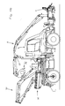
- Figures 3 and 4 show a work vehicle with a verge mower 1, which comprises a total of three separate cutter heads 2a, 2b and 32, of which each is attached to a separate cantilever arm 3, 4 and 33.
- the vehicle differs from that of Figures 1 and 2 only by the third working unit, i.e. the rear mowing head 32, which is on a separate Tail boom 33 is attached, and another storage type of the second Mowing head 2b in the transport position.
- the third working unit i.e. the rear mowing head 32, which is on a separate Tail boom 33 is attached, and another storage type of the second Mowing head 2b in the transport position.
- this rear cantilever arm 33 is this rear mowing head 32 by means of a sliding base 29 along rear offset rails 28 in the transverse direction arranged on the front part of the loading area 5 of the vehicle 7 and slidable there for weight adjustment.
- the Sliding base 29 - relative to when mowing to the right of the vehicle positioned far right outside in particular on the right edge of the loading area 5 to be able to dimension the rear cantilever arm 33 as short as possible.
- the second and third work unit, the two most distant working units, are very similar, in particular have the same Mowing head 2b, 32 and also the outrigger arms 4, 33 are very similar or are identical.
- Figures 4 show the Transport position.
- the third mowing head 32 lies in the transport position on the loading area 5 in its outer area and approximately parallel to the Driving direction on the loading area or above the loading area 5. He is in addition to the - viewed in the side view of Figure 4 - C-shaped retracted rear boom 33, which is still the rear over the Loading area 5 stands out, and for better weight distribution and around the side enough space for the stored rear mower head 32 to create something of the Mowing head away from the center of the loading area 5 along the rear offset rail 38 has proceeded.
- the rear boom 33 extends from the front Area of the loading area from - viewed from the side - rising obliquely backwards.
- the second mowing head 2 is positioned in the transport position in which it is in Transverse position to the direction of travel and under the supporting end of the extension arm 4 folded in height is held approximately above the center of the loading area 5.
- extension arm 4 - which is in the transport position extends backwards about the driver's cabin in the middle of the vehicle - is placed on a storage rail 27, which is preferably above the front End of the loading area 5 or mounted above the driver's cab 6 and such Height has that the mowing head 2b deposited in this way does not match the in Transport position located rear storage arm 33 collides.
- a fixed storage program is preferably for taking up the transport position programmed so that first the third mounted on the rear Mower unit brought into transport position, and only then the second one Mower unit is placed with the second mower head 2b in the transport position.
- the transport position can be assumed simultaneously or only afterwards the first mower unit (extension arm 3 with mowing head 2a) in front of the front rail take place, which takes place analogously to the description of Figures 1 and 2.
Landscapes
- Life Sciences & Earth Sciences (AREA)
- Environmental Sciences (AREA)
- Harvester Elements (AREA)
- Shovels (AREA)
Abstract
Description
- Fig. 1a, 1b
- das Randstreifenmähgerät mit zwei Mähköpfen beim Mähen in Aufsicht und Frontansicht und
- Fig. 2a, 2b
- das Arbeitsgerät in Transportstellung der Fig. 1 in der Seitenansicht und Aufsicht.
- Fig. 3a, 3b
- ein Arbeitsfahrzeug mit drei Mähköpfen in Arbeitsstellung in der Aufsicht und Frontansicht.
- Fig. 4a, 4b
- das Arbeitsgerät gemäß Fig. 3 in der Transportstellung in Aufsicht und Seitenansicht.
- 1
- Randstreifen-Mähgerät
- 2a,b
- Mähkopf (innerer/äußerer)
- 3
- Auslegerarm (2a)
- 4
- Auslegerarm (2b)
- 5
- Ladefläche
- 6
- Fahrerkabine
- 7
- Arbeitsfahrzeug
- 8
- Frontrahmen
- 9
- Befestigungspunkt
- 10
- Fahrtrichtung
- 11
- Versatzschiene
- 12
- Taststange
- 13
- Abtastwalze
- 14
- Abtastwalze
- 16a,b
- Mähwelle
- 17
- teleskopierbarer Abschnitt
- 18
- Anlenkpunkt
- 19
- Querrichtung
- 20
- Straße
- 21
- Randstreifen
- 22
- Straßen-Begrenzungspfosten
- 23
- äußerer Punkt
- 24
- Stoßstange
- 25
- Verschiebeschuh
- 26
- Befestigungsschuh
- 27
- Ablagschiene
- 28
- Heck-Versatzschiene
- 29
- Schiebebasis
- 32
- Heck-Mähkopf
- 33
- Heck-Auslegerarm
Claims (19)
- Arbeitsfahrzeug (7) mit einem Randstreifen-Mähgerät (1) mit wenigstens zwei seitlich zueinander und zum Arbeitsfahrzeug (7) versetzt vor der Fahrerkabine (6) arbeitenden Mähköpfen (2a, b ...),
dadurch gekennzeichnet, dass
der Auslegerarm (4) des weiter außen arbeitenden Mähkopfes (2b) so ausgelegt ist, dass in der Transportstellung ein Ablegen dieses äußeren Mähkopfes (2b) über, insbesondere auf der Ladefläche (5) des Arbeitsfahrzeuges (7) hinter der Fahrerkabine (6) möglich ist. - Mähgerät nach Anspruch 1,
dadurch gekennzeichnet, dass
sich in der Transportstellung der zweite Auslegerarm (4) des Mähkopfes (2b) über die Fahrerkabine (6) hinweg erstreckt und seitlich nicht über das Arbeitsfahrzeug (7) hinausragt, und insbesondere der zweite Auslegerarm (4) mittig, insbesondere ausschließlich mittig, am Mähkopf (2b) angesetzt ist. - Mähgerät nach einem der vorhergehenden Ansprüche,
dadurch gekennzeichnet, dass
der seitlich betrachtet am nächsten am Arbeitsfahrzeug (7) arbeitende Mähkopf (2a) hinsichtlich seiner rotierenden Mähelemente und/oder seines Gehäuses - quer zur Fahrtrichtung (10) betrachtet - einen kleineren, insbesondere nur halb so großen Durchmesser aufweist wie der weiter außen arbeitende Mähkopf (2b), und insbesondere die Drehzahl des ganz innen arbeitenden Mähkopfes (2b) größer, insbesondere wenigstens zweimal so groß wie die des weiter außen arbeitenden Mähkopfes (2a) ist, und insbesondere der wenigstens eine weiter außen arbeitende Mähkopf (2b) eine Breite quer zur Fahrtrichtung (10) besitzt, die mehr als 50% der Gesamtbreite des Arbeitsfahrzeuges beträgt. - Mähgerät nach einem der vorhergehenden Ansprüche,
dadurch gekennzeichnet, dass
der innen arbeitende Mähkopf (2a) als Mähelement eine Messerwelle mit entlang wenigstens einer Wendel angeordneten Messern aufweist. - Mähgerät nach einem der vorhergehenden Ansprüche,
dadurch gekennzeichnet, dass
das Randstreifen-Mähgerät (1) einen Frontrahmen (8) zur Befestigung an der Front des Arbeitsfahrzeuges (7) sowie eine vor diesem Frontrahmen (8) quer zur Fahrtrichtung (10) verlaufende Versatzschiene (11) umfaßt, entlang welcher der zweite Auslegerarm (4) des weiter außen arbeitenden Mähkopfes (2b) während des Arbeitseinsatzes quer zur Fahrtrichtung (10) verfahrbar ist, und insbesondere der erste Auslegerarm (3) des innen arbeitenden Mähkopfes (2a) an dem der Fahrerseite gegenüberliegenden, in der Regel rechten, Ende des Frontrahmens (8), insbesondere dessen Versatzschiene (11), ortsfest angeordnet ist. - Mähgerät nach einem der vorhergehenden Ansprüche,
dadurch gekennzeichnet, dass
der innen arbeitende Mähkopf (2a) in Arbeitsstellung so weit in Fahrtrichtung (10) vor dem weiter außen arbeitenden Mähkopf (2b) positioniert ist, dass ein Verschwenken des weiter innen arbeitenden Mähkopfes (2a) um den an seinem linken Ende angeordneten Befestigungspunkt (9) bezüglich seines ersten Auslegerarmes (3) nach hinten zwecks Umfahren von Hindernissen ohne Kollision mit dem äußeren Mähkopf (2b) möglich ist. - Mähgerät nach einem der vorhergehenden Ansprüche,
dadurch gekennzeichnet, dass
vor dem inneren Mähkopf (2a) eine Taststange (12) quer zur Fahrrichtung und verschwenkbar am Gehäuse des Mähkopfes (2a), insbesondere schwenkbar befestigt auf der Seite des Befestigungspunktes (9), angeordnet ist. - Mähgerät nach einem der vorhergehenden Ansprüche,
dadurch gekennzeichnet, dass
der erste Auslegerarm (3) in der Arbeitsstellung des zugeordneten Mähkopfes (2a) parallel zur Fahrtrichtung (10) vom äußeren Rand des Frontrahmens (8), insbesondere von dessen Versatzschiene (11) und damit des Arbeitsfahrzeuges (7), aus gerade nach vorne verläuft, und insbesondere der erste Auslegerarm (3) einen parallelogrammartigen oder teleskopierbaren Abschnitt (3') aufweist. - Mähgerät nach einem der vorhergehenden Ansprüche,
dadurch gekennzeichnet, dass
der erste Auslegerarm (3) des inneren Mähkopfes (2a) so ausgebildet ist, dass der innere Mähkopf (2a) in Transportstellung parallel vor der Versatzschiene (11) angeordnet, und insbesondere in der Transportstellung mit seinem freien Ende auf der Fahrerseite auf einer Ablage des Mähgerätes (1), die insbesondere Teil der Befestigung des zweiten Auslegerarmes (4) des äußeren Mähkopfes (2b) an der Versatzschiene (11) ist, ablegbar ist, insbesondere so, daß dessen Taststange (12) vor dem Gehäuse des Mähkopfes (2a) angeordnet ist. - Mähgerät nach einem der vorhergehenden Ansprüche,
dadurch gekennzeichnet, dass
die beiden oder drei Mähköpfe (2a, b ...) unabhängig voneinander, insbesondere automatisch oder wahlweise manuell, hinsichtlich ihres Seitenversatzes und/oder ihrer Längsposition vor dem Frontrahmen (8) und damit auch hinsichtlich ihrer seitlichen Überlappung steuerbar sind, und insbesondere wenigstens ein Mähkopf, insbesondere der nicht innen arbeitende Mähkopf (2b), einen Sensor zur Abtastung der Form des Untergrundes, insbesondere mittels einer Abtastwalze (14, 13), insbesondere eine nachlaufende, zwecks automatischer Höhen- bzw. Neigungseinstellung des Mähkopfes (2b) aufweist. - Mähgerät nach einem der vorhergehenden Ansprüche,
dadurch gekennzeichnet, dass
der Auslegerarm (4) des außen arbeitenden Mähkopfes (2b) in der Transportstellung hinsichtlich seiner Querposition an der Versatzschiene (11) des Frontrahmens (8) vom Fahrer unter Berücksichtigung ausreichender Sicht für den Fahrer auf die Fahrbahn positionierbar, insbesondere im mittleren Bereich positionierbar, ist, unter insbesondere automatischer Beibehaltung der gleichen, insbesondere mittigen, Ablageposition des Mähkopfes (2b) auf der in Querrichtung mittigen Position der Ladefläche (5). - Mähgerät nach einem der vorhergehenden Ansprüche,
dadurch gekennzeichnet, dass
bei (3), jeweils an einem Auslegerarm (3, 4, 33) angeordneten Mähköpfen (2a,b, 32) ein Auslegerarm als Heck-Auslegerarm (33) ausgebildet ist und auf der Ladefläche (5) und/oder einer hinter der Ladefläche angeordneten Heckschiene des Arbeitsfahrzeuges (7) angebaut ist. - Mähgerät nach einem der vorhergehenden Ansprüche,
dadurch gekennzeichnet, dass
der Heck-Mähkopf (32) des Heck-Auslegerarms (33) der am Arbeitseinsatz am weitesten außen, also seitlich zum Arbeitsfahrzeug (7) beabstandete, Mähkopf ist. - Mähgerät nach einem der vorhergehenden Ansprüche,
dadurch gekennzeichnet, dass
der im Arbeitseinsatz mittlere Mähkopf (2b) und ganz außen arbeitende Heck-Mähkopf (32) identisch ausgebildet sind. - Mähgerät nach einem der vorhergehenden Ansprüche,
dadurch gekennzeichnet, dass
der Heck-Auslegerarm (33) auf einer Schiebebasis (29) befestigt ist, die in Querrichtung des Arbeitsfahrzeuges (7) entlang einer Heck-Versatzschiene (28) verfahrbar ist. - Mähgerät nach einem der vorhergehenden Ansprüche,
dadurch gekennzeichnet, dass
in der Transportstellung der mittlere Mähkopf (2b) im Abstand über der Ladefläche (5) angeordnet ist, in dem der zugehörige zweite Auslegerarm (4) auf einer Ablageschiene (27), die in Querrichtung verlaufend über dem vorderen Endbereich der Ladefläche (5) in einer Höhe oberhalb des oberen Endes der Fahrerkabine (6) angeordnet ist, aufliegt und insbesondere dabei der Mähkopf (2b) nach vorne weisend unter das freie Ende seines zweiten Auslegerarmes (4) geklappt ist. - Mähgerät nach einem der vorhergehenden Ansprüche,
dadurch gekennzeichnet, dass
in der Transportstellung der Heck-Mähkopf (32) seitlich neben dem eingeklappten Heck-Auslegerarm (33) oberhalb, insbesondere auf, der Ladefläche (5), insbesondere in Längsrichtung verlaufend, angeordnet ist oder in Querrichtung verlaufend hinter dem hinteren Ende der Ladefläche (5) angeordnet ist. - Mähgerät nach einem der vorhergehenden Ansprüche,
dadurch gekennzeichnet, dass
in der Transportstellung der Heck-Auslegerarm (33) von der Längsmitte aus etwas versetzt, von dem abgelegten Heck-Mähkopf (32) weg versetzt, zur Gewichtsverteilung entlang der Heck-Versatzschiene (28) verfahren ist. - Mähgerät nach einem der vorhergehenden Ansprüche,
dadurch gekennzeichnet, dass
in der Transportstellung der Heck-Auslegerarm (33) von seiner Schiebebasis (29) aus nach hinten verlaufend unter in Transportstellung befindlichen mittleren Mähkopf (2b) hindurch verläuft.
Priority Applications (1)
| Application Number | Priority Date | Filing Date | Title |
|---|---|---|---|
| DE20122186U DE20122186U1 (de) | 2000-05-31 | 2001-05-07 | Mähgerät mit zwei Mähköpfen |
Applications Claiming Priority (2)
| Application Number | Priority Date | Filing Date | Title |
|---|---|---|---|
| DE10027133 | 2000-05-31 | ||
| DE10027133A DE10027133B4 (de) | 2000-05-31 | 2000-05-31 | Mähgerät mit zwei Mähköpfen |
Publications (2)
| Publication Number | Publication Date |
|---|---|
| EP1159866A1 true EP1159866A1 (de) | 2001-12-05 |
| EP1159866B1 EP1159866B1 (de) | 2004-07-21 |
Family
ID=7644317
Family Applications (1)
| Application Number | Title | Priority Date | Filing Date |
|---|---|---|---|
| EP01110996A Expired - Lifetime EP1159866B1 (de) | 2000-05-31 | 2001-05-07 | Mähgerät mit zwei Mähköpfen |
Country Status (3)
| Country | Link |
|---|---|
| EP (1) | EP1159866B1 (de) |
| AT (1) | ATE271307T1 (de) |
| DE (2) | DE10027133B4 (de) |
Cited By (8)
| Publication number | Priority date | Publication date | Assignee | Title |
|---|---|---|---|---|
| EP1364572A1 (de) * | 2002-05-15 | 2003-11-26 | Laserjet S.r.l. | Buschmäherfahrzeug |
| EP1759573A1 (de) * | 2005-04-22 | 2007-03-07 | Gerhard Dücker GmbH & Co. KG Landmaschinenfabrik | Mäh- und/oder Schneidgerät |
| EP1900274A1 (de) | 2006-09-12 | 2008-03-19 | Deere & Company | Mechanismus zur Versetzung von Schneideeinheiten für einen Rasenmäher und Rasenmäher |
| WO2011034487A1 (en) * | 2009-09-15 | 2011-03-24 | Bertil Karlsson | Vehicle mounted lift arm assembly |
| ITBO20090660A1 (it) * | 2009-10-13 | 2011-04-14 | Hymach S R L | Veicolo tosaerba multifunzione |
| DE102014110996A1 (de) * | 2014-08-01 | 2016-02-04 | Jörg Reeb | Lastkraftwagen |
| EP3469872A1 (de) * | 2017-10-12 | 2019-04-17 | MULAG FAHRZEUGWERK Heinz Wössner GmbH & CO. KG | Arbeitsgerät, arbeitsfahrzeug mit einem solchen arbeitsgerät, baukasten zum herstellen des arbeitsgerätes sowie verfahren zum betreiben wenigstens des arbeitsgerätes |
| EP3831187B1 (de) * | 2019-12-04 | 2024-04-03 | MULAG FAHRZEUGWERK Heinz Wössner GmbH & CO. KG | Ausleger-arbeitsgerät, selbstfahrende arbeitsmaschine mit einem solchen ausleger-arbeitsgerät sowie ein verfahren zum detektieren der auf den ausleger einwirkenden belastungen |
Families Citing this family (3)
| Publication number | Priority date | Publication date | Assignee | Title |
|---|---|---|---|---|
| DE10221327A1 (de) * | 2002-05-14 | 2004-06-09 | MULAG FAHRZEUGWERK Heinz Wössner GmbH & Co. KG | Mähgerät mit Pfosten-Freimäher |
| DE10321683B4 (de) * | 2003-05-14 | 2008-05-15 | MULAG FAHRZEUGWERK Heinz Wössner GmbH & Co. KG | Pfosten-Freimäher und Verfahren zum Einsatz des Freimähers |
| DE102017211839A1 (de) | 2017-07-11 | 2019-01-17 | Robert Bosch Gmbh | Steuersystem für ein Agrararbeitssystem, Arbeitssystem, Verwendung |
Citations (8)
| Publication number | Priority date | Publication date | Assignee | Title |
|---|---|---|---|---|
| DE3318342A1 (de) * | 1983-05-20 | 1984-11-22 | Epoke Süd Alfred Thomsen GmbH & Co KG, 6405 Eichenzell | Fuer die pritsche eines arbeitsfahrzeugs bestimmte auslegeranordnung |
| GB2180133A (en) * | 1985-07-10 | 1987-03-25 | Smalley Excavators Ltd | Mowing machine for embankments |
| US4697405A (en) * | 1985-12-24 | 1987-10-06 | Dewitt Carl | Mowing apparatus |
| DE4408750C1 (de) * | 1994-03-15 | 1995-02-16 | Schmidt Holding Europ Gmbh | An einem Trägerfahrzeug heckseitig anbaubares Mähgerät |
| US5392593A (en) * | 1993-04-26 | 1995-02-28 | Emery Tree Service, Inc. | Mobile apparatus for cutting vegetation |
| DE19611281A1 (de) * | 1996-03-22 | 1997-09-25 | Fiedler Maschinenbau Und Techn | Auflagedruckregelung für ein am Erdboden arbeitendes landwirtschaftliches Arbeitswerkzeug |
| DE29909876U1 (de) * | 1999-05-31 | 1999-08-26 | Goedde Maschinenbau Gmbh | Trägerfahrzeug mit angebautem Arbeitsgerät, insbesondere Mähgerät |
| DE20003154U1 (de) * | 2000-02-22 | 2000-05-04 | Duecker Gerhard Gmbh & Co Kg | Mähgerät |
Family Cites Families (2)
| Publication number | Priority date | Publication date | Assignee | Title |
|---|---|---|---|---|
| DE3042510A1 (de) * | 1980-11-11 | 1982-06-24 | Mulag-Fahrzeugwerk Heinz Wössner KG, 7605 Bad Peterstal-Griesbach | Zum absaugen von organischen abfaellen u.dgl. von strassenraendern, banketten, graeben und boeschungen dienendes sauggeraet |
| DE29909878U1 (de) * | 1999-05-31 | 1999-08-26 | Goedde Maschinenbau Gmbh | Anbaugerät für Trägerfahrzeug |
-
2000
- 2000-05-31 DE DE10027133A patent/DE10027133B4/de not_active Expired - Lifetime
-
2001
- 2001-05-07 EP EP01110996A patent/EP1159866B1/de not_active Expired - Lifetime
- 2001-05-07 AT AT01110996T patent/ATE271307T1/de active
- 2001-05-07 DE DE50102903T patent/DE50102903D1/de not_active Expired - Lifetime
Patent Citations (8)
| Publication number | Priority date | Publication date | Assignee | Title |
|---|---|---|---|---|
| DE3318342A1 (de) * | 1983-05-20 | 1984-11-22 | Epoke Süd Alfred Thomsen GmbH & Co KG, 6405 Eichenzell | Fuer die pritsche eines arbeitsfahrzeugs bestimmte auslegeranordnung |
| GB2180133A (en) * | 1985-07-10 | 1987-03-25 | Smalley Excavators Ltd | Mowing machine for embankments |
| US4697405A (en) * | 1985-12-24 | 1987-10-06 | Dewitt Carl | Mowing apparatus |
| US5392593A (en) * | 1993-04-26 | 1995-02-28 | Emery Tree Service, Inc. | Mobile apparatus for cutting vegetation |
| DE4408750C1 (de) * | 1994-03-15 | 1995-02-16 | Schmidt Holding Europ Gmbh | An einem Trägerfahrzeug heckseitig anbaubares Mähgerät |
| DE19611281A1 (de) * | 1996-03-22 | 1997-09-25 | Fiedler Maschinenbau Und Techn | Auflagedruckregelung für ein am Erdboden arbeitendes landwirtschaftliches Arbeitswerkzeug |
| DE29909876U1 (de) * | 1999-05-31 | 1999-08-26 | Goedde Maschinenbau Gmbh | Trägerfahrzeug mit angebautem Arbeitsgerät, insbesondere Mähgerät |
| DE20003154U1 (de) * | 2000-02-22 | 2000-05-04 | Duecker Gerhard Gmbh & Co Kg | Mähgerät |
Cited By (11)
| Publication number | Priority date | Publication date | Assignee | Title |
|---|---|---|---|---|
| EP1364572A1 (de) * | 2002-05-15 | 2003-11-26 | Laserjet S.r.l. | Buschmäherfahrzeug |
| EP1759573A1 (de) * | 2005-04-22 | 2007-03-07 | Gerhard Dücker GmbH & Co. KG Landmaschinenfabrik | Mäh- und/oder Schneidgerät |
| EP1759572A1 (de) * | 2005-04-22 | 2007-03-07 | Gerhard Dücker GmbH & Co. KG Landmaschinenfabrik | Mäh- und/oder Schneidgerät |
| EP2213156A3 (de) * | 2005-04-22 | 2011-10-05 | Gerhard Dücker GmbH & Co. KG Landmaschinenfabrik | Mäh- und/oder Schneidgerät |
| EP1900274A1 (de) | 2006-09-12 | 2008-03-19 | Deere & Company | Mechanismus zur Versetzung von Schneideeinheiten für einen Rasenmäher und Rasenmäher |
| US7654065B2 (en) | 2006-09-12 | 2010-02-02 | Deere & Company | Offsetting cutting units for a grass mowing machine |
| WO2011034487A1 (en) * | 2009-09-15 | 2011-03-24 | Bertil Karlsson | Vehicle mounted lift arm assembly |
| ITBO20090660A1 (it) * | 2009-10-13 | 2011-04-14 | Hymach S R L | Veicolo tosaerba multifunzione |
| DE102014110996A1 (de) * | 2014-08-01 | 2016-02-04 | Jörg Reeb | Lastkraftwagen |
| EP3469872A1 (de) * | 2017-10-12 | 2019-04-17 | MULAG FAHRZEUGWERK Heinz Wössner GmbH & CO. KG | Arbeitsgerät, arbeitsfahrzeug mit einem solchen arbeitsgerät, baukasten zum herstellen des arbeitsgerätes sowie verfahren zum betreiben wenigstens des arbeitsgerätes |
| EP3831187B1 (de) * | 2019-12-04 | 2024-04-03 | MULAG FAHRZEUGWERK Heinz Wössner GmbH & CO. KG | Ausleger-arbeitsgerät, selbstfahrende arbeitsmaschine mit einem solchen ausleger-arbeitsgerät sowie ein verfahren zum detektieren der auf den ausleger einwirkenden belastungen |
Also Published As
| Publication number | Publication date |
|---|---|
| EP1159866B1 (de) | 2004-07-21 |
| DE50102903D1 (de) | 2004-08-26 |
| DE10027133B4 (de) | 2005-03-03 |
| ATE271307T1 (de) | 2004-08-15 |
| DE10027133A1 (de) | 2001-12-20 |
Similar Documents
| Publication | Publication Date | Title |
|---|---|---|
| EP0073360B1 (de) | Mähmaschine | |
| DE10346818A1 (de) | Selbstfahrendes Grossflächenmähwerk | |
| EP1159866B1 (de) | Mähgerät mit zwei Mähköpfen | |
| EP0674734A1 (de) | Pistenpflegevorrichtung. | |
| EP0807377A2 (de) | Vorrichtung zum Anschliessen eines aus der Arbeitsstellung in eine Transportstellung höhenverstellbares Gerätes an ein Fahrzeug | |
| DE60205226T2 (de) | Buschmäherfahrzeug | |
| EP2213156B1 (de) | Mäh- und/oder Schneidgerät | |
| DE10321683B4 (de) | Pfosten-Freimäher und Verfahren zum Einsatz des Freimähers | |
| EP3266292B1 (de) | Landwirtschaftliches anhängegerät und zuggespann mit einem solchen anhängegerät | |
| EP3479678B1 (de) | Sägevorrichtung zum zuschneiden von pflanzen | |
| DE1927793A1 (de) | Kombinierte Abtast-Maehmaschine | |
| EP0545351B1 (de) | Trägergerät für ein Arbeitswerkzeug | |
| EP3323283A1 (de) | Auslegerarm sowie mit einem solchen auslegerarm ausgestattetes ausleger-arbeitsgerät | |
| DE20122186U1 (de) | Mähgerät mit zwei Mähköpfen | |
| DE202005006541U1 (de) | Mäh- und/oder Schneidgerät | |
| EP3616495A1 (de) | Befestigungsmechanismus für eine zerkleinerungs- / schneidvorrichtung für pflanzenmaterial an einem fahrzeug, insbesondere einem traktor oder ähnlichem | |
| DE19931281A1 (de) | Wagen zum Transport eines Schneidwerks | |
| AT523600B1 (de) | Mähwerksanordnung | |
| DE102009030905B4 (de) | Mäh- und/oder Schneidgerät | |
| DE10221327A1 (de) | Mähgerät mit Pfosten-Freimäher | |
| DE2745230A1 (de) | Geraet zum flaechenbearbeiten, insbesondere zum ebenfraesen, von strassenbanketten und hierbei insbesondere von mit leitplanken versehenen banketten | |
| DE10027453A1 (de) | Arbeitsmaschine | |
| DE102022101571A1 (de) | Ausleger-Arbeitsgerät sowie Verfahren zum Herumführen eines Arbeitskopfes des Ausleger-Arbeitsgerätes um ein Hindernis | |
| DE202007009109U1 (de) | Vorrichtung zum Schneiden von Reben | |
| EP1716742A1 (de) | Vorrichtung zur Futterernte |
Legal Events
| Date | Code | Title | Description |
|---|---|---|---|
| PUAI | Public reference made under article 153(3) epc to a published international application that has entered the european phase |
Free format text: ORIGINAL CODE: 0009012 |
|
| AK | Designated contracting states |
Kind code of ref document: A1 Designated state(s): AT BE CH CY DE DK ES FI FR GB GR IE IT LI LU MC NL PT SE TR Kind code of ref document: A1 Designated state(s): AT CH DE FR GB IT LI |
|
| AX | Request for extension of the european patent |
Free format text: AL;LT;LV;MK;RO;SI |
|
| 17P | Request for examination filed |
Effective date: 20020515 |
|
| AKX | Designation fees paid |
Free format text: AT CH DE FR GB IT LI |
|
| GRAP | Despatch of communication of intention to grant a patent |
Free format text: ORIGINAL CODE: EPIDOSNIGR1 |
|
| GRAS | Grant fee paid |
Free format text: ORIGINAL CODE: EPIDOSNIGR3 |
|
| GRAA | (expected) grant |
Free format text: ORIGINAL CODE: 0009210 |
|
| AK | Designated contracting states |
Kind code of ref document: B1 Designated state(s): AT CH DE FR GB IT LI |
|
| REG | Reference to a national code |
Ref country code: GB Ref legal event code: FG4D Free format text: NOT ENGLISH |
|
| REG | Reference to a national code |
Ref country code: CH Ref legal event code: EP |
|
| GBT | Gb: translation of ep patent filed (gb section 77(6)(a)/1977) |
Effective date: 20040721 |
|
| REG | Reference to a national code |
Ref country code: IE Ref legal event code: FG4D Free format text: GERMAN |
|
| REF | Corresponds to: |
Ref document number: 50102903 Country of ref document: DE Date of ref document: 20040826 Kind code of ref document: P |
|
| REG | Reference to a national code |
Ref country code: CH Ref legal event code: NV Representative=s name: SCHMAUDER & PARTNER AG PATENTANWALTSBUERO Ref country code: CH Ref legal event code: PFA Owner name: MULAG-FAHRZEUGWERK HEINZ WOESSNER GMBH & CO. KG Free format text: MULAG-FAHRZEUGWERK HEINZ WOESSNER GMBH & CO KG#STOECKMATT 11#D-77740 BAD PETERSTAL-GRIESBACH (DE) -TRANSFER TO- MULAG-FAHRZEUGWERK HEINZ WOESSNER GMBH & CO. KG#GEWERBESTRASSE 8#77728 OPPENAU (DE) |
|
| ET | Fr: translation filed | ||
| REG | Reference to a national code |
Ref country code: IE Ref legal event code: FD4D |
|
| PLAQ | Examination of admissibility of opposition: information related to despatch of communication + time limit deleted |
Free format text: ORIGINAL CODE: EPIDOSDOPE2 |
|
| PLBQ | Unpublished change to opponent data |
Free format text: ORIGINAL CODE: EPIDOS OPPO |
|
| PLAQ | Examination of admissibility of opposition: information related to despatch of communication + time limit deleted |
Free format text: ORIGINAL CODE: EPIDOSDOPE2 |
|
| PLAR | Examination of admissibility of opposition: information related to receipt of reply deleted |
Free format text: ORIGINAL CODE: EPIDOSDOPE4 |
|
| PLBQ | Unpublished change to opponent data |
Free format text: ORIGINAL CODE: EPIDOS OPPO |
|
| PLBI | Opposition filed |
Free format text: ORIGINAL CODE: 0009260 |
|
| PLAQ | Examination of admissibility of opposition: information related to despatch of communication + time limit deleted |
Free format text: ORIGINAL CODE: EPIDOSDOPE2 |
|
| PLAR | Examination of admissibility of opposition: information related to receipt of reply deleted |
Free format text: ORIGINAL CODE: EPIDOSDOPE4 |
|
| PLBQ | Unpublished change to opponent data |
Free format text: ORIGINAL CODE: EPIDOS OPPO |
|
| PLAB | Opposition data, opponent's data or that of the opponent's representative modified |
Free format text: ORIGINAL CODE: 0009299OPPO |
|
| PLAX | Notice of opposition and request to file observation + time limit sent |
Free format text: ORIGINAL CODE: EPIDOSNOBS2 |
|
| 26 | Opposition filed |
Opponent name: G. DUECKER GMBH & CO.KG LANDMASCHINEN Effective date: 20050420 |
|
| R26 | Opposition filed (corrected) |
Opponent name: G. DUECKER GMBH & CO.KG LANDMASCHINEN Effective date: 20050420 |
|
| PLBB | Reply of patent proprietor to notice(s) of opposition received |
Free format text: ORIGINAL CODE: EPIDOSNOBS3 |
|
| PLAY | Examination report in opposition despatched + time limit |
Free format text: ORIGINAL CODE: EPIDOSNORE2 |
|
| PLAH | Information related to despatch of examination report in opposition + time limit modified |
Free format text: ORIGINAL CODE: EPIDOSCORE2 |
|
| PLAZ | Examination of admissibility of opposition: despatch of communication + time limit |
Free format text: ORIGINAL CODE: EPIDOSNOPE2 |
|
| PLBI | Opposition filed |
Free format text: ORIGINAL CODE: 0009260 |
|
| PLBP | Opposition withdrawn |
Free format text: ORIGINAL CODE: 0009264 |
|
| PLBA | Examination of admissibility of opposition: reply received |
Free format text: ORIGINAL CODE: EPIDOSNOPE4 |
|
| 26 | Opposition filed |
Opponent name: G. DUECKER GMBH & CO.KG LANDMASCHINEN Effective date: 20050420 Opponent name: PROJEKT MASCHINENBAU GMBH Effective date: 20070312 |
|
| PLBC | Reply to examination report in opposition received |
Free format text: ORIGINAL CODE: EPIDOSNORE3 |
|
| PLAY | Examination report in opposition despatched + time limit |
Free format text: ORIGINAL CODE: EPIDOSNORE2 |
|
| PLAH | Information related to despatch of examination report in opposition + time limit modified |
Free format text: ORIGINAL CODE: EPIDOSCORE2 |
|
| PLAF | Information modified related to communication of a notice of opposition and request to file observations + time limit |
Free format text: ORIGINAL CODE: EPIDOSCOBS2 |
|
| PLAH | Information related to despatch of examination report in opposition + time limit modified |
Free format text: ORIGINAL CODE: EPIDOSCORE2 |
|
| PLAB | Opposition data, opponent's data or that of the opponent's representative modified |
Free format text: ORIGINAL CODE: 0009299OPPO |
|
| PLBD | Termination of opposition procedure: decision despatched |
Free format text: ORIGINAL CODE: EPIDOSNOPC1 |
|
| PLBM | Termination of opposition procedure: date of legal effect published |
Free format text: ORIGINAL CODE: 0009276 |
|
| STAA | Information on the status of an ep patent application or granted ep patent |
Free format text: STATUS: OPPOSITION PROCEDURE CLOSED |
|
| 27C | Opposition proceedings terminated |
Effective date: 20081020 |
|
| REG | Reference to a national code |
Ref country code: CH Ref legal event code: PCAR Free format text: SCHMAUDER & PARTNER AG PATENT- UND MARKENANWAELTE VSP;ZWAENGIWEG 7;8038 ZUERICH (CH) |
|
| REG | Reference to a national code |
Ref country code: DE Ref legal event code: R082 Ref document number: 50102903 Country of ref document: DE Representative=s name: PATENTANWAELTE WEICKMANN & WEICKMANN, DE Ref country code: DE Ref legal event code: R082 Ref document number: 50102903 Country of ref document: DE Representative=s name: WEICKMANN & WEICKMANN PATENTANWAELTE - RECHTSA, DE Ref country code: DE Ref legal event code: R082 Ref document number: 50102903 Country of ref document: DE Representative=s name: WEICKMANN & WEICKMANN PATENT- UND RECHTSANWAEL, DE |
|
| REG | Reference to a national code |
Ref country code: FR Ref legal event code: PLFP Year of fee payment: 16 |
|
| REG | Reference to a national code |
Ref country code: FR Ref legal event code: PLFP Year of fee payment: 17 |
|
| REG | Reference to a national code |
Ref country code: FR Ref legal event code: PLFP Year of fee payment: 18 |
|
| PGFP | Annual fee paid to national office [announced via postgrant information from national office to epo] |
Ref country code: DE Payment date: 20190730 Year of fee payment: 19 |
|
| PGFP | Annual fee paid to national office [announced via postgrant information from national office to epo] |
Ref country code: CH Payment date: 20200522 Year of fee payment: 20 Ref country code: FR Payment date: 20200519 Year of fee payment: 20 |
|
| PGFP | Annual fee paid to national office [announced via postgrant information from national office to epo] |
Ref country code: IT Payment date: 20200528 Year of fee payment: 20 Ref country code: GB Payment date: 20200522 Year of fee payment: 20 |
|
| PGFP | Annual fee paid to national office [announced via postgrant information from national office to epo] |
Ref country code: AT Payment date: 20200515 Year of fee payment: 20 |
|
| REG | Reference to a national code |
Ref country code: DE Ref legal event code: R119 Ref document number: 50102903 Country of ref document: DE |
|
| REG | Reference to a national code |
Ref country code: CH Ref legal event code: PL |
|
| REG | Reference to a national code |
Ref country code: GB Ref legal event code: PE20 Expiry date: 20210506 |
|
| PG25 | Lapsed in a contracting state [announced via postgrant information from national office to epo] |
Ref country code: DE Free format text: LAPSE BECAUSE OF NON-PAYMENT OF DUE FEES Effective date: 20201201 |
|
| REG | Reference to a national code |
Ref country code: AT Ref legal event code: MK07 Ref document number: 271307 Country of ref document: AT Kind code of ref document: T Effective date: 20210507 |
|
| PG25 | Lapsed in a contracting state [announced via postgrant information from national office to epo] |
Ref country code: GB Free format text: LAPSE BECAUSE OF EXPIRATION OF PROTECTION Effective date: 20210506 |