EP1158255A2 - Heizkessel - Google Patents
Heizkessel Download PDFInfo
- Publication number
- EP1158255A2 EP1158255A2 EP01250182A EP01250182A EP1158255A2 EP 1158255 A2 EP1158255 A2 EP 1158255A2 EP 01250182 A EP01250182 A EP 01250182A EP 01250182 A EP01250182 A EP 01250182A EP 1158255 A2 EP1158255 A2 EP 1158255A2
- Authority
- EP
- European Patent Office
- Prior art keywords
- module
- boiler
- condensate
- heat exchanger
- exhaust gases
- Prior art date
- Legal status (The legal status is an assumption and is not a legal conclusion. Google has not performed a legal analysis and makes no representation as to the accuracy of the status listed.)
- Withdrawn
Links
Images

Classifications
-
- F—MECHANICAL ENGINEERING; LIGHTING; HEATING; WEAPONS; BLASTING
- F24—HEATING; RANGES; VENTILATING
- F24H—FLUID HEATERS, e.g. WATER OR AIR HEATERS, HAVING HEAT-GENERATING MEANS, e.g. HEAT PUMPS, IN GENERAL
- F24H9/00—Details
- F24H9/14—Arrangements for connecting different sections, e.g. in water heaters
-
- F—MECHANICAL ENGINEERING; LIGHTING; HEATING; WEAPONS; BLASTING
- F24—HEATING; RANGES; VENTILATING
- F24H—FLUID HEATERS, e.g. WATER OR AIR HEATERS, HAVING HEAT-GENERATING MEANS, e.g. HEAT PUMPS, IN GENERAL
- F24H8/00—Fluid heaters characterised by means for extracting latent heat from flue gases by means of condensation
- F24H8/006—Means for removing condensate from the heater
-
- F—MECHANICAL ENGINEERING; LIGHTING; HEATING; WEAPONS; BLASTING
- F24—HEATING; RANGES; VENTILATING
- F24H—FLUID HEATERS, e.g. WATER OR AIR HEATERS, HAVING HEAT-GENERATING MEANS, e.g. HEAT PUMPS, IN GENERAL
- F24H9/00—Details
- F24H9/14—Arrangements for connecting different sections, e.g. in water heaters
- F24H9/148—Arrangements of boiler components on a frame or within a casing to build the fluid heater, e.g. boiler
-
- Y—GENERAL TAGGING OF NEW TECHNOLOGICAL DEVELOPMENTS; GENERAL TAGGING OF CROSS-SECTIONAL TECHNOLOGIES SPANNING OVER SEVERAL SECTIONS OF THE IPC; TECHNICAL SUBJECTS COVERED BY FORMER USPC CROSS-REFERENCE ART COLLECTIONS [XRACs] AND DIGESTS
- Y02—TECHNOLOGIES OR APPLICATIONS FOR MITIGATION OR ADAPTATION AGAINST CLIMATE CHANGE
- Y02B—CLIMATE CHANGE MITIGATION TECHNOLOGIES RELATED TO BUILDINGS, e.g. HOUSING, HOUSE APPLIANCES OR RELATED END-USER APPLICATIONS
- Y02B30/00—Energy efficient heating, ventilation or air conditioning [HVAC]
Definitions
- the invention relates to a boiler arranged in the upper part Combustion chamber and a burner, the hot exhaust gases of which the boiler heating surfaces in the Falling current are brought into contact with a heat exchanger.
- the channels of the heat exchanger have a rectangular cross section and have passage spaces for the flow of the hot exhaust gases for the heating of the combustion air.
- the pipes for transporting the combustion air to be heated are formed from a plastic that is resistant to heat and aggression of the exhaust gases. For better handling and easier assembly of the heat exchanger, the pipes and elbows are brought together by simple plug connections.
- the document further states that the special construction of the preheater with the heat exchanger and its position associated with the boiler enables the air heated by the exhaust gases to be used for heating purposes, in particular for space heating purposes.
- DE 40 37 986 A1 presents a tube heat exchanger in which the combustion gases flow through tubes. Combustion gases in the sense of the technical solution presented here mean exhaust gases from the boiler function.
- the tubes of the heat exchanger are enclosed by the combustion air to be heated. They give off their heat to the combustion air.
- the cooling creates a condensate, which is deposited in the pipes and held by projections similar to a dam. It is a disadvantage of this solution according to the invention that the condensate with its aggressive substances is backed up in the pipes and can have a caustic effect on the inner walls of the pipes.
- the document further shows that the pipes and the elbows of the connector are held together in the manner of a socket connection.
- the invention has for its object a boiler, with one in the upper Burner chamber arranged burner, the hot exhaust gases of which are the primary heating surfaces of the Cover the boiler in the downflow and connect it with a tubular heat exchanger are brought to create, which makes it possible to achieve high throughput values and a uncomplicated separation and insertion of the heat exchanger and the Condensate collector allowed.
- the object is achieved by a boiler, with a burner arranged in the upper part of the burner chamber, the hot exhaust gases of which pass over the primary heating surfaces of the boiler in a falling flow, which has a tubular heat exchanger which is connected to the boiler in a separately designed module .
- the module is detachably connected and movable with the exhaust gas led out of the boiler via an inlet pipe inserted in its cover plate. Tube bundles of a heat exchanger are provided in the module, which take over the heat from the hot exhaust gases.
- the heat exchanger is arranged on a collecting tray, which condensate is led through a passage in its lowest point into a condensate collector.
- the collector is filled with substances for detoxifying the condensate, for the outlet of which a drain in the module is provided via a further pipe.
- the heat exchanger, the collecting tray for the condensate underneath and the condensate collector formed therewith are arranged in the module, with inlet and outlet lines for the hot exhaust gases, with inlets and outlets for the preheated burner chamber air and the condensate drainage via sliding plug connections for a Movement of the complete module equipped for installation and removal, trained.
- the module is designed in such a way that it enables a functional arrangement and alternating movement in the boiler.
- it consists of interconnected top, bottom and side surfaces into which receptacles for pipe passages and cleaning openings are incorporated.
- the module has a bottom surface which is brought into operative connection with the boiler as a footprint.
- a passage is arranged at the deepest point of the inclined collecting tray, which discharges the condensate into a condensate collector which, arranged under the collecting tray, is equipped with separating surfaces which are shaped as overflow plates and baffles inclined from above against the bottom .
- the guide plates protruding from above against the floor are provided with a passage gap in the area of the floor.
- the condensate can thus be directed through the chambers of the condensate collector in an intermittently guided pass.
- passage openings for pipe connections to be used as well as supply and cleaning openings are provided in the sides of the module designed as front and rear surfaces.
- the module is closed on the side surfaces, so that the fully populated module can advantageously be inserted smoothly into the boiler.
- the invention obtains an advantageous embodiment in that the outlet opening for the exhaust gases of the module used in the heating boilers is connected to an approximately horizontal pipe section which is inclined downwards towards the heating boiler and which is articulated in a vertical pipe section in which a suction fan is arranged is.
- the pipe section is arranged above the collecting floor, opening into the module.
- the module is slidably movable in the boiler.
- the solution according to the invention has the advantage that the boiler is equipped with a separately movable module.
- the essential elements of the heat exchanger and its peripheral functional parts are arranged in the module, thus allowing simple assembly and uncomplicated prefabrication of the boiler.
- the operating and maintenance options are significantly simpler than with conventional boilers, because following the advantages of the solution according to the invention, the maintenance and repair work can be carried out separately and side by side. In accordance with the essence of the invention, it is possible to maintain or repair the module regardless of the location of the boiler and to replace it with the one already in the boiler.
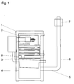
- the boiler 1 is in its overall functional concept over a to the boiler 1 inclined pipe section 5 and a vertically articulated pipe section 6 with connected to the chimney head.
- a suction blower 7 is located below the Schomsteinkopf arranged in the pipe section 6, the exhaust gases from the lower region of the Sucks off boiler 1 and the downflow in the boiler necessary for its function generated.
- the pipe section 5 with its downward inclination to the boiler 1 allows a safe return of the condensate formed in the pipe sections 5; 6.
- An air inlet 3 of the heated combustion air coming from the bottom arranged module 4 leads into the burner chamber 2 is by a corresponding Cable secured.
- the from the burner chamber 2 via the heating surfaces in the downflow air entering below is introduced into the module 4 via an inlet line 8 and sweeps over the tube bundle 9 of the tube heat exchanger arranged in module 4, so as is provided in Fig. 2.
- the module 4 consists of a self-contained Container in which the essential functional parts for air preheating and Condensate collection and its treatment and discharge are classified.
- the Module 4 can be opened by loosening the plug connections, in particular for the air access 3 for the pipe section 5, for the exhaust gas outlet 14 and the condensate outlet 23 including the inlet line 8 for the hot exhaust gas to be supplied easily and can be removed compactly from the boiler 1.
- the connections of the functional Pipe connections 3; 8; 14; 23 are easy to remove and reconnect Connector 19; 19 '; 19 "made so that easy handling in the Functional production of the one to be used and for dismantling the one to be removed Module 4 is possible.
- the self-contained and fully equipped Module 4 carries in its upper area the tube bundle 9 of the heat exchanger. in the lower area of the module 4, from its rear wall to the front, over the Reaching the entire width, an inclined catch floor 10 is incorporated, which in the area of Front has a passage 11 through which the on the collecting base 10th precipitating condensate of the tube bundle 9 of the heat exchanger and the Backflow from the pipe sections 5; 6 into the condensate module 4 into one Condensate collector 12 arrives.
- the condensate collector 12 is between the bottom of the Catch floor 10 and the bottom surface 20 of the module 4 are formed. It consists of several parallel chambers, which are filled with granules 13, and through Overflow plates 16; 16 'and baffles 15; 15' arranged between them Preserve functional shape and position.
- the condensate is now in the sump of the Condensate collector 12 led from a first chamber to a second, with a Overflow passed over the overflow plate 16 into a third chamber and passes through the second pass 17 into a fourth, the overflow plate 16 'up to the level of Connection 19 "is sufficient for the drainage of the condensate.
- All are Connections 19; 19 '; 19 "of the functional pipe connections with detachable plug connections equipped.
- An equally easy-to-use connection is given one Cleaning opening 18, which is incorporated in the end face of the module 4.
- Module 4 stands with its bottom surface 20 on a contact surface 21 of the boiler 1, the is professionally trained as a sliding plane and guidance.
- the module 4 can be removed from the boiler 1.
- the insertion of the possible exchange module and its module is just as easy Connection with the functional connecting parts and pipes. It is also possible, through the cleaning opening 18 into the module 4 to see its state check.
Landscapes
- Engineering & Computer Science (AREA)
- Physics & Mathematics (AREA)
- Thermal Sciences (AREA)
- Chemical & Material Sciences (AREA)
- Combustion & Propulsion (AREA)
- Mechanical Engineering (AREA)
- General Engineering & Computer Science (AREA)
- Heat-Exchange Devices With Radiators And Conduit Assemblies (AREA)
Abstract
Description
Die DE 40 37 986 A1 stellt einen Röhrenwärmetauscher vor, bei dem Rohre von Verbrennungsgasen durchströmt sind. Unter Verbrennungsgase im Sinne der hier vorgeführten technischen Lösung werden Abgase aus der Kesselfunktion verstanden. Die Röhren des Wärmetauschers sind dabei von der zu erwärmenden Verbrennungsluft umschlossen. Sie geben ihre Wärme an die Verbrennungsluft ab. Durch die Abkühlung entsteht ein Kondensat, das sich in den Rohren niederschlägt und durch staudammähnliche Vorsprünge gehalten wird. Es ist ein Nachteil dieser erfindungsgemäßen Lösung, dass das Kondensat mit seinen aggressiven Substanzen in den Rohren zurückgestaut wird und ätzend auf die Innenwände der Rohre einwirken kann. Die Schrift stellt weiter dar, dass die Rohre und die Krümmer der Steckverbindung in der Art einer Muffenverbindung zusammengehalten werden.
Entsprechend einer sinnvollen Ausbildung der Erfindung ist das Modul mit dem aus dem Heizkessel geführten Abgas über ein in seiner Deckplatte eingeführtes Eintrittsrohr lösbar verbunden und bewegbar. In dem Modul sind Rohrbündel eines Wärmetauschers vorgesehen, die von den heißen Abgasen die Wärme übernehmen. Der Wärmetauscher befindet sich über einen Fangboden eingeordnet, der anfallendes Kondensat über einen Durchlauf in seiner tiefsten Stelle in einen Kondensatsammler führt. Der Sammler ist mit Stoffen zum Entgiften des Kondensats angefüllt, für dessen Austritt ein Abfluss im Modul über ein weiterführendes Rohr vorgesehen ist. Die Erfindung ausbildend, sind der Wärmetauscher, der darunter gelegene Fangboden für das Kondensat sowie der damit ausgebildete Kondensatsammler im Modul eingeordnet, mit Eingangs- und Ausgangsleitungen für die heißen Abgase, mit Zu- und Ableitungen der vorgewärmten Brennerraumluft sowie der Kondensatableitung über gleitende Steckverbindungen für eine Bewegung des kompletten Moduls zum Ein- und Ausbau ausgerüstet, ausgebildet.
In vorteilhafter Ausbildung der Erfindung ist an der tiefsten Stelle des geneigten Fangbodens ein Durchlass angeordnet, der das Kondensat in einen Kondensatsammler ableitet, der, unter dem Fangboden angeordnet, mit Trennflächen bestückt ist, die als Überlaufbleche und von oben gegen den Boden geneigte Leitbleche ausgeformt sind. Die von oben gegen den Boden ragenden Leitbleche sind im Bereich des Bodens mit einem Durchlaufspalt versehen. Das Kondensat kann damit in einem intermittierend geführten Durchlauf durch die Kammern des Kondensatsammlers gelenkt werden. Nach einer weiteren erfindungsgemäß vorteilhaften Ausbildung sind in den als Stirn- und Rückflächen ausgebildeten Seiten des Moduls Durchtrittsöffnungen für einzusetzende Rohrverbindungen sowie Versorgungs- und Reinigungsöffnungen vorgesehen. Das Modul ist an den Seitenflächen geschlossen, so dass vorteilhafterweise ein glattes Einschieben des vollständig bestückten Moduls in den Heizkessel durchführbar ist. Eine vorteilhafte Ausgestaltung erhält die Erfindung dadurch, dass die Ausgangsöffnung für die Abgase des in den Heizkesseln eingesetzten Moduls mit einer annähernd horizontal verlaufenden, nach unten gegen den Heizkessel geneigten Rohrsektion verbunden ist, die sich in einer vertikalen Rohrsektion angelenkt fortsetzt, in der ein Sauggebläse angeordnet ist. Die Erfindung ausbildend, ist die Rohrsektion über dem Fangboden, in das Modul einmündend, angeordnet. Nach einer vorteilhaften Gestaltung der erfindungsgemäßen Lösung ist das Modul in den Heizkessel gleitend bewegbar einzuordnen.
Die erfindungsgemäße Lösung weist den Vorteil auf, dass der Heizkessel mit einem separat bewegbaren Modul ausgestattet ist. In dem Modul sind die wesentlichen Elemente des Wärmetauschers und dessen periphere Funktionsteile eingeordnet und damit eine einfache Montage und unkomplizierte Vorfertigung des Heizkessels gestattet. Die Bedienungs- und Wartungsmöglichkeiten sind bedeutend einfacher als bei den herkömmlichen Heizkesseln, weil den Vorteilen der erfindungsgemäßen Lösung folgend, die Wartungs- und Reparaturarbeiten für sich separat und nebeneinander laufend vorgenommen werden können. So ist es dem Wesen der Erfindung folgend möglich, das Modul unabhängig vom Standort des Heizkessels zu warten oder zu reparieren und gegen das bereits im Kessel befindliche auszutauschen.
- Fig. 1:
- Den Heizkessel in einer schematischen Darstellung;
- Fig. 2:
- Den Wärmetauscher, eingeordnet in ein Modul, im Schnitt.
- 1
- Heizkessel
- 2
- Brennerraum
- 3
- Luftzugang
- 4
- Modul
- 5;6
- Rohrsektion
- 7
- Sauggebläse
- 8
- Eingangsleitung
- 9
- Rohrbündel
- 10
- Fangboden
- 11
- Durchlass
- 12
- Kondensatsammler
- 13
- Granulat
- 14
- Abgasauslass
- 15,15'
- Leitblech
- 16,16'
- Überlaufblech
- 17
- Durchlauf
- 18
- Reinigungsöffnung
- 19;19';19"
- Verbindung
- 20
- Bodenfläche
- 21
- Aufstandfläche
- 22
- Deckplatte
- 23
- Kondensatauslass
- 24
- Ableitung
- 25
- Abfluss
Claims (11)
- Heizkessel (1) mit einem, im oberen Teil des Kessels im Brennerraum (2) eingeordneten Brenner, dessen heiße Abgase die Primärheizflächen des Kessel (1) in einem Fallstrom überstreichen und einem Rohrwärmetauscher, der mit dem Heizkessel (1) in einem separat ausgebildeten Modul (4) angeordnet, verbunden ist.
- Heizkessel nach Anspruch 1, dadurch gekennzeichnet, dass das Modul (4) aus dem Heizkessel (1) mit einem in seiner Deckplatte (22) eingefügten Eintrittsrohr (8) lösbar verbunden, bewegbar ist, und in seinem Innenraum Rohrbündel (9) eines Wärmetauschers vorgesehen, die von heißen Abgasen Wärme übernehmend, über einem Fangboden (10) eingeordnet sind, der das Kondensat über einen Durchlauf an seiner tiefsten Stelle in einen Kondensatsammler (12) führt, der mit Stoffen zum Entgiften des Kondensats angefüllt, und für dessen Austritt ein Abfluss (25) im Modul (4) als ein weiterführendes Rohr vorgesehen ist.
- Heizkessel nach den Ansprüchen 1 und 2, dadurch gekennzeichnet, dass der Wärmetauscher und der Fangboden (10) für das Kondensat sowie der darunter gebildete Kondensatssammler (12) in dem Modul (4) eingeordnet sind und mit der Eingangs- und Ausgangsleitung (8;5) für die heißen Abgase sowie der Zuleitung (3) und Ableitung (24) der vorgewärmten Brennerraumluft sowie Kondensatableitungen (25) über gleitende Steckverbindungen (19;19';19") verfügen, welche für eine Bewegung des kompletten Moduls (4) zum Ein- und Ausbau leicht lösbar ausgebildet sind.
- Modul für einen Heizkessel aus miteinander verbundenen Deck-, Boden- und Seitenflächen, in die Aufnahmeeinrichtungen für Rohrdurchgänge und Reinigungsöffnungen (18) eingearbeitet und mit dem im Modul (4) eingeordneten Wärmetauscher sowie dem Kondensatsammler (12) verbunden sind, einen Boden (20) aufweist, der als Aufstandfläche (21) mit einem Heizkessel (1) in eine Wirkverbindung gebracht ist.
- Modul nach Anspruch 4, dadurch gekennzeichnet, dass der Fangboden (10) in Richtung eines Durchlasses (11) für das Kondensat geneigt ausgebildet ist.
- Modul nach den Ansprüchen 4 und 5, dadurch gekennzeichnet, dass der Kondensatsammler (12) mit Trennflächen bestückt ist, die mit Überlaufblechen (16;16') und mit von oben gegen den Boden (20) gerichteten Leitblechen (15;15') mit einem unteren Durchlauf (17), Kammern bildend, das Kondensat mit einem intermittierenden Durchfluss durch die Kammern lenkend, vorgesehen ist.
- Modul nach Anspruch 4, dadurch gekennzeichnet, dass in den als Stirn- und Rückenflächen ausgebildeten Seiten des Moduls (4) Durchtrittsöffnungen für einzusetzende Rohrverbindungen (19;19';19") sowie Versorgungs- und Reinigungsöffnungen (18) vorgesehen sind.
- Modul nach Anspruch 4, dadurch gekennzeichnet, dass seine Seitenflächen geschlossen sind.
- Heizkessel nach den Ansprüchen 1 bis 3, dadurch gekennzeichnet, dass die Ausgangsöffnung (14) des eingeordneten Moduls (4) für die abgekühlten Abgase mit einer annähernd horizontal verlaufenden, nach unten gegen den Heizkessel (1) geneigten Rohrsektion (5) verbunden ist, die sich an eine vertikale Rohrsektion (6) angelenkt fortsetzt, in deren Bereich ein Sauggebläse (7) angeordnet ist.
- Heizkessel nach den Ansprüchen 1 bis 3, dadurch gekennzeichnet, dass über die geneigte Rohrsektion (5) das Kondensat in das Modul (4) geleitet ist.
- Heizkessel nach den Ansprüchen 1 bis 3, dadurch gekennzeichnet, dass das Modul (4) in den Heizkessel (1) gleitend bewegbar einzuordnen ist.
Applications Claiming Priority (4)
| Application Number | Priority Date | Filing Date | Title |
|---|---|---|---|
| DE10025729 | 2000-05-25 | ||
| DE20009261U DE20009261U1 (de) | 2000-05-25 | 2000-05-25 | Heizkessel |
| DE20009261U | 2000-05-25 | ||
| DE10025729A DE10025729A1 (de) | 2000-05-25 | 2000-05-25 | Heizkessel |
Publications (2)
| Publication Number | Publication Date |
|---|---|
| EP1158255A2 true EP1158255A2 (de) | 2001-11-28 |
| EP1158255A3 EP1158255A3 (de) | 2003-05-07 |
Family
ID=26005815
Family Applications (1)
| Application Number | Title | Priority Date | Filing Date |
|---|---|---|---|
| EP01250182A Withdrawn EP1158255A3 (de) | 2000-05-25 | 2001-05-23 | Heizkessel |
Country Status (1)
| Country | Link |
|---|---|
| EP (1) | EP1158255A3 (de) |
Cited By (1)
| Publication number | Priority date | Publication date | Assignee | Title |
|---|---|---|---|---|
| CN111223790A (zh) * | 2018-11-27 | 2020-06-02 | 未来宝株式会社 | 半导体工艺的反应副产物收集装置 |
Citations (2)
| Publication number | Priority date | Publication date | Assignee | Title |
|---|---|---|---|---|
| DE4037986A1 (de) | 1990-11-29 | 1992-06-04 | Richard Vetter | Roehrenwaermeaustauscher |
| DE4037987A1 (de) | 1990-11-29 | 1992-06-04 | Richard Vetter | Roehrenwaermeaustauscher |
Family Cites Families (4)
| Publication number | Priority date | Publication date | Assignee | Title |
|---|---|---|---|---|
| FR2503845B1 (fr) * | 1981-04-08 | 1986-05-09 | Dietrich Sa | Chaudiere a condensation de puissance industrielle |
| DE3536667A1 (de) * | 1985-10-15 | 1987-04-16 | Richard Vetter | Geraet zum erwaermen von wasser, insb. warmwasserheizkessel |
| EP0939284A3 (de) * | 1998-02-26 | 2001-09-12 | Richard Vetter | Gerät zum Erwärmen von Wasser, insbesondere Warmwasserheizkessel |
| DE29900238U1 (de) * | 1999-01-11 | 1999-08-12 | Zimmermann, Bernd, 06120 Halle | Brennwertbrenner |
-
2001
- 2001-05-23 EP EP01250182A patent/EP1158255A3/de not_active Withdrawn
Patent Citations (2)
| Publication number | Priority date | Publication date | Assignee | Title |
|---|---|---|---|---|
| DE4037986A1 (de) | 1990-11-29 | 1992-06-04 | Richard Vetter | Roehrenwaermeaustauscher |
| DE4037987A1 (de) | 1990-11-29 | 1992-06-04 | Richard Vetter | Roehrenwaermeaustauscher |
Cited By (2)
| Publication number | Priority date | Publication date | Assignee | Title |
|---|---|---|---|---|
| CN111223790A (zh) * | 2018-11-27 | 2020-06-02 | 未来宝株式会社 | 半导体工艺的反应副产物收集装置 |
| CN111223790B (zh) * | 2018-11-27 | 2023-05-23 | 未来宝株式会社 | 半导体工艺的反应副产物收集装置 |
Also Published As
| Publication number | Publication date |
|---|---|
| EP1158255A3 (de) | 2003-05-07 |
Similar Documents
| Publication | Publication Date | Title |
|---|---|---|
| DE3614385C2 (de) | ||
| DE2819185A1 (de) | Fliessbett-verbrennungsvorrichtung | |
| CH616499A5 (en) | Central heating system with a boiler and an additional heat exchanger for preheating the medium flowing back to the boiler | |
| DE102005009202A1 (de) | Blockwärmetauscher für staubhaltige Rauchgase | |
| DE3315135A1 (de) | Dampferzeuger mit fliessbettfeuerung | |
| EP0138890A1 (de) | Einrichtung zur behandlung von verbrennungsgasen. | |
| WO2012055504A1 (de) | Lüftungsanordnung mit einer dunstabzugshaube | |
| DE112007003550T5 (de) | Kessel mit flachen horizontalen Röhren | |
| DE19723407B4 (de) | Einrichtung zur Rückgewinnung von Abwärmeenergie an Durchlauföfen | |
| EP0632238A1 (de) | Verfahren und Vorrichtung zur Rückgewinnung von Wärme aus den Abgasen von Feuerungsanlagen mit einem Wärmetauscher | |
| DE236647T1 (de) | Wirbelbettwaermeerzeuger mit mitteln fuer aschenbeseitigung und waermerueckgewinnung. | |
| DE10025729A1 (de) | Heizkessel | |
| DE20009261U1 (de) | Heizkessel | |
| EP1158255A2 (de) | Heizkessel | |
| EP2351966B1 (de) | Wärmetauschersystem | |
| DE19510993C1 (de) | Vorrichtung zur thermischen Abgasbehandlung, insbesondere von oxidierbaren Schwelgasen | |
| EP0507167A2 (de) | Rauchgasführung an einem Heizkessel | |
| DE3217146A1 (de) | Vorrichtung zur entstaubung von kreislaufgas einer kokstrockenkuehlanlage | |
| DE3218608A1 (de) | Vorrichtung und verfahren zur nutzung heisser abgase | |
| DE202006003153U1 (de) | Energierückgewinnungsmodul | |
| EP0190616A2 (de) | Gerät zum Erwärmen von Wasser, insb. Warmwasserheizkessel | |
| EP4483096B1 (de) | Vorrichtung zur behandlung von abgasen einer kleinfeuerungsanlage | |
| DE29807361U1 (de) | Heizungsgerät | |
| DE3110205C2 (de) | Kaminanordnung für Feuerungsanlagen | |
| AT10016U1 (de) | Festbrennstoffkessel |
Legal Events
| Date | Code | Title | Description |
|---|---|---|---|
| PUAI | Public reference made under article 153(3) epc to a published international application that has entered the european phase |
Free format text: ORIGINAL CODE: 0009012 |
|
| AK | Designated contracting states |
Kind code of ref document: A2 Designated state(s): AT BE CH CY DE DK ES FI FR GB GR IE IT LI LU MC NL PT SE TR |
|
| AX | Request for extension of the european patent |
Free format text: AL;LT;LV;MK;RO;SI |
|
| PUAL | Search report despatched |
Free format text: ORIGINAL CODE: 0009013 |
|
| AK | Designated contracting states |
Designated state(s): AT BE CH CY DE DK ES FI FR GB GR IE IT LI LU MC NL PT SE TR |
|
| AX | Request for extension of the european patent |
Extension state: AL LT LV MK RO SI |
|
| AKX | Designation fees paid | ||
| REG | Reference to a national code |
Ref country code: DE Ref legal event code: 8566 |
|
| STAA | Information on the status of an ep patent application or granted ep patent |
Free format text: STATUS: THE APPLICATION IS DEEMED TO BE WITHDRAWN |
|
| 18D | Application deemed to be withdrawn |
Effective date: 20031108 |