EP1157930A2 - Vorrichtung und Verfahren zum Versiegeln für eine Verpackungsmaschine - Google Patents
Vorrichtung und Verfahren zum Versiegeln für eine Verpackungsmaschine Download PDFInfo
- Publication number
- EP1157930A2 EP1157930A2 EP01110234A EP01110234A EP1157930A2 EP 1157930 A2 EP1157930 A2 EP 1157930A2 EP 01110234 A EP01110234 A EP 01110234A EP 01110234 A EP01110234 A EP 01110234A EP 1157930 A2 EP1157930 A2 EP 1157930A2
- Authority
- EP
- European Patent Office
- Prior art keywords
- tracks
- dies
- film
- die
- sealing
- Prior art date
- Legal status (The legal status is an assumption and is not a legal conclusion. Google has not performed a legal analysis and makes no representation as to the accuracy of the status listed.)
- Withdrawn
Links
- 238000007789 sealing Methods 0.000 title claims abstract description 101
- 238000000034 method Methods 0.000 title claims description 20
- 238000004806 packaging method and process Methods 0.000 title description 9
- 230000000712 assembly Effects 0.000 claims abstract description 39
- 238000000429 assembly Methods 0.000 claims abstract description 39
- 230000007246 mechanism Effects 0.000 claims description 3
- 238000010438 heat treatment Methods 0.000 claims 1
- 239000002985 plastic film Substances 0.000 abstract description 5
- 229920006255 plastic film Polymers 0.000 abstract description 5
- 230000001133 acceleration Effects 0.000 description 13
- 238000006243 chemical reaction Methods 0.000 description 4
- 230000005484 gravity Effects 0.000 description 3
- 238000013459 approach Methods 0.000 description 2
- 238000005520 cutting process Methods 0.000 description 2
- 230000003247 decreasing effect Effects 0.000 description 2
- 238000011144 upstream manufacturing Methods 0.000 description 2
- 229910000760 Hardened steel Inorganic materials 0.000 description 1
- 229920006362 Teflon® Polymers 0.000 description 1
- 230000006835 compression Effects 0.000 description 1
- 238000007906 compression Methods 0.000 description 1
- 238000010276 construction Methods 0.000 description 1
- 230000036461 convulsion Effects 0.000 description 1
- 238000001816 cooling Methods 0.000 description 1
- 230000000694 effects Effects 0.000 description 1
- 230000002452 interceptive effect Effects 0.000 description 1
- 229920001296 polysiloxane Polymers 0.000 description 1
- 230000001737 promoting effect Effects 0.000 description 1
- 230000007704 transition Effects 0.000 description 1
Images


Classifications
-
- B—PERFORMING OPERATIONS; TRANSPORTING
- B65—CONVEYING; PACKING; STORING; HANDLING THIN OR FILAMENTARY MATERIAL
- B65B—MACHINES, APPARATUS OR DEVICES FOR, OR METHODS OF, PACKAGING ARTICLES OR MATERIALS; UNPACKING
- B65B25/00—Packaging other articles presenting special problems
- B65B25/14—Packaging paper or like sheets, envelopes, or newspapers, in flat, folded, or rolled form
- B65B25/146—Packaging paper or like sheets, envelopes, or newspapers, in flat, folded, or rolled form packaging rolled-up articles
-
- B—PERFORMING OPERATIONS; TRANSPORTING
- B29—WORKING OF PLASTICS; WORKING OF SUBSTANCES IN A PLASTIC STATE IN GENERAL
- B29C—SHAPING OR JOINING OF PLASTICS; SHAPING OF MATERIAL IN A PLASTIC STATE, NOT OTHERWISE PROVIDED FOR; AFTER-TREATMENT OF THE SHAPED PRODUCTS, e.g. REPAIRING
- B29C65/00—Joining or sealing of preformed parts, e.g. welding of plastics materials; Apparatus therefor
- B29C65/02—Joining or sealing of preformed parts, e.g. welding of plastics materials; Apparatus therefor by heating, with or without pressure
- B29C65/18—Joining or sealing of preformed parts, e.g. welding of plastics materials; Apparatus therefor by heating, with or without pressure using heated tools
- B29C65/22—Heated wire resistive ribbon, resistive band or resistive strip
- B29C65/221—Heated wire resistive ribbon, resistive band or resistive strip characterised by the type of heated wire, resistive ribbon, band or strip
- B29C65/224—Heated wire resistive ribbon, resistive band or resistive strip characterised by the type of heated wire, resistive ribbon, band or strip being a resistive ribbon, a resistive band or a resistive strip
-
- B—PERFORMING OPERATIONS; TRANSPORTING
- B29—WORKING OF PLASTICS; WORKING OF SUBSTANCES IN A PLASTIC STATE IN GENERAL
- B29C—SHAPING OR JOINING OF PLASTICS; SHAPING OF MATERIAL IN A PLASTIC STATE, NOT OTHERWISE PROVIDED FOR; AFTER-TREATMENT OF THE SHAPED PRODUCTS, e.g. REPAIRING
- B29C65/00—Joining or sealing of preformed parts, e.g. welding of plastics materials; Apparatus therefor
- B29C65/02—Joining or sealing of preformed parts, e.g. welding of plastics materials; Apparatus therefor by heating, with or without pressure
- B29C65/18—Joining or sealing of preformed parts, e.g. welding of plastics materials; Apparatus therefor by heating, with or without pressure using heated tools
- B29C65/22—Heated wire resistive ribbon, resistive band or resistive strip
- B29C65/221—Heated wire resistive ribbon, resistive band or resistive strip characterised by the type of heated wire, resistive ribbon, band or strip
- B29C65/226—Heated wire resistive ribbon, resistive band or resistive strip characterised by the type of heated wire, resistive ribbon, band or strip characterised by the cross-section of said heated wire, resistive ribbon, resistive band or resistive strip, e.g. being triangular
-
- B—PERFORMING OPERATIONS; TRANSPORTING
- B29—WORKING OF PLASTICS; WORKING OF SUBSTANCES IN A PLASTIC STATE IN GENERAL
- B29C—SHAPING OR JOINING OF PLASTICS; SHAPING OF MATERIAL IN A PLASTIC STATE, NOT OTHERWISE PROVIDED FOR; AFTER-TREATMENT OF THE SHAPED PRODUCTS, e.g. REPAIRING
- B29C65/00—Joining or sealing of preformed parts, e.g. welding of plastics materials; Apparatus therefor
- B29C65/74—Joining or sealing of preformed parts, e.g. welding of plastics materials; Apparatus therefor by welding and severing, or by joining and severing, the severing being performed in the area to be joined, next to the area to be joined, in the joint area or next to the joint area
- B29C65/743—Joining or sealing of preformed parts, e.g. welding of plastics materials; Apparatus therefor by welding and severing, or by joining and severing, the severing being performed in the area to be joined, next to the area to be joined, in the joint area or next to the joint area using the same tool for both joining and severing, said tool being monobloc or formed by several parts mounted together and forming a monobloc
-
- B—PERFORMING OPERATIONS; TRANSPORTING
- B29—WORKING OF PLASTICS; WORKING OF SUBSTANCES IN A PLASTIC STATE IN GENERAL
- B29C—SHAPING OR JOINING OF PLASTICS; SHAPING OF MATERIAL IN A PLASTIC STATE, NOT OTHERWISE PROVIDED FOR; AFTER-TREATMENT OF THE SHAPED PRODUCTS, e.g. REPAIRING
- B29C66/00—General aspects of processes or apparatus for joining preformed parts
- B29C66/01—General aspects dealing with the joint area or with the area to be joined
- B29C66/05—Particular design of joint configurations
- B29C66/10—Particular design of joint configurations particular design of the joint cross-sections
- B29C66/11—Joint cross-sections comprising a single joint-segment, i.e. one of the parts to be joined comprising a single joint-segment in the joint cross-section
- B29C66/112—Single lapped joints
- B29C66/1122—Single lap to lap joints, i.e. overlap joints
-
- B—PERFORMING OPERATIONS; TRANSPORTING
- B29—WORKING OF PLASTICS; WORKING OF SUBSTANCES IN A PLASTIC STATE IN GENERAL
- B29C—SHAPING OR JOINING OF PLASTICS; SHAPING OF MATERIAL IN A PLASTIC STATE, NOT OTHERWISE PROVIDED FOR; AFTER-TREATMENT OF THE SHAPED PRODUCTS, e.g. REPAIRING
- B29C66/00—General aspects of processes or apparatus for joining preformed parts
- B29C66/40—General aspects of joining substantially flat articles, e.g. plates, sheets or web-like materials; Making flat seams in tubular or hollow articles; Joining single elements to substantially flat surfaces
- B29C66/41—Joining substantially flat articles ; Making flat seams in tubular or hollow articles
- B29C66/43—Joining a relatively small portion of the surface of said articles
- B29C66/431—Joining the articles to themselves
- B29C66/4312—Joining the articles to themselves for making flat seams in tubular or hollow articles, e.g. transversal seams
-
- B—PERFORMING OPERATIONS; TRANSPORTING
- B29—WORKING OF PLASTICS; WORKING OF SUBSTANCES IN A PLASTIC STATE IN GENERAL
- B29C—SHAPING OR JOINING OF PLASTICS; SHAPING OF MATERIAL IN A PLASTIC STATE, NOT OTHERWISE PROVIDED FOR; AFTER-TREATMENT OF THE SHAPED PRODUCTS, e.g. REPAIRING
- B29C66/00—General aspects of processes or apparatus for joining preformed parts
- B29C66/80—General aspects of machine operations or constructions and parts thereof
- B29C66/81—General aspects of the pressing elements, i.e. the elements applying pressure on the parts to be joined in the area to be joined, e.g. the welding jaws or clamps
- B29C66/814—General aspects of the pressing elements, i.e. the elements applying pressure on the parts to be joined in the area to be joined, e.g. the welding jaws or clamps characterised by the design of the pressing elements, e.g. of the welding jaws or clamps
- B29C66/8141—General aspects of the pressing elements, i.e. the elements applying pressure on the parts to be joined in the area to be joined, e.g. the welding jaws or clamps characterised by the design of the pressing elements, e.g. of the welding jaws or clamps characterised by the surface geometry of the part of the pressing elements, e.g. welding jaws or clamps, coming into contact with the parts to be joined
- B29C66/81427—General aspects of the pressing elements, i.e. the elements applying pressure on the parts to be joined in the area to be joined, e.g. the welding jaws or clamps characterised by the design of the pressing elements, e.g. of the welding jaws or clamps characterised by the surface geometry of the part of the pressing elements, e.g. welding jaws or clamps, coming into contact with the parts to be joined comprising a single ridge, e.g. for making a weakening line; comprising a single tooth
-
- B—PERFORMING OPERATIONS; TRANSPORTING
- B29—WORKING OF PLASTICS; WORKING OF SUBSTANCES IN A PLASTIC STATE IN GENERAL
- B29C—SHAPING OR JOINING OF PLASTICS; SHAPING OF MATERIAL IN A PLASTIC STATE, NOT OTHERWISE PROVIDED FOR; AFTER-TREATMENT OF THE SHAPED PRODUCTS, e.g. REPAIRING
- B29C66/00—General aspects of processes or apparatus for joining preformed parts
- B29C66/80—General aspects of machine operations or constructions and parts thereof
- B29C66/81—General aspects of the pressing elements, i.e. the elements applying pressure on the parts to be joined in the area to be joined, e.g. the welding jaws or clamps
- B29C66/814—General aspects of the pressing elements, i.e. the elements applying pressure on the parts to be joined in the area to be joined, e.g. the welding jaws or clamps characterised by the design of the pressing elements, e.g. of the welding jaws or clamps
- B29C66/8145—General aspects of the pressing elements, i.e. the elements applying pressure on the parts to be joined in the area to be joined, e.g. the welding jaws or clamps characterised by the design of the pressing elements, e.g. of the welding jaws or clamps characterised by the constructional aspects of the pressing elements, e.g. of the welding jaws or clamps
- B29C66/81457—General aspects of the pressing elements, i.e. the elements applying pressure on the parts to be joined in the area to be joined, e.g. the welding jaws or clamps characterised by the design of the pressing elements, e.g. of the welding jaws or clamps characterised by the constructional aspects of the pressing elements, e.g. of the welding jaws or clamps comprising a block or layer of deformable material, e.g. sponge, foam, rubber
-
- B—PERFORMING OPERATIONS; TRANSPORTING
- B29—WORKING OF PLASTICS; WORKING OF SUBSTANCES IN A PLASTIC STATE IN GENERAL
- B29C—SHAPING OR JOINING OF PLASTICS; SHAPING OF MATERIAL IN A PLASTIC STATE, NOT OTHERWISE PROVIDED FOR; AFTER-TREATMENT OF THE SHAPED PRODUCTS, e.g. REPAIRING
- B29C66/00—General aspects of processes or apparatus for joining preformed parts
- B29C66/80—General aspects of machine operations or constructions and parts thereof
- B29C66/82—Pressure application arrangements, e.g. transmission or actuating mechanisms for joining tools or clamps
- B29C66/822—Transmission mechanisms
- B29C66/8226—Cam mechanisms; Wedges; Eccentric mechanisms
- B29C66/82263—Follower pin or roller cooperating with a groove
-
- B—PERFORMING OPERATIONS; TRANSPORTING
- B29—WORKING OF PLASTICS; WORKING OF SUBSTANCES IN A PLASTIC STATE IN GENERAL
- B29C—SHAPING OR JOINING OF PLASTICS; SHAPING OF MATERIAL IN A PLASTIC STATE, NOT OTHERWISE PROVIDED FOR; AFTER-TREATMENT OF THE SHAPED PRODUCTS, e.g. REPAIRING
- B29C66/00—General aspects of processes or apparatus for joining preformed parts
- B29C66/80—General aspects of machine operations or constructions and parts thereof
- B29C66/83—General aspects of machine operations or constructions and parts thereof characterised by the movement of the joining or pressing tools
- B29C66/834—General aspects of machine operations or constructions and parts thereof characterised by the movement of the joining or pressing tools moving with the parts to be joined
- B29C66/8351—Jaws mounted on rollers, cylinders, drums, bands, belts or chains; Flying jaws
-
- B—PERFORMING OPERATIONS; TRANSPORTING
- B29—WORKING OF PLASTICS; WORKING OF SUBSTANCES IN A PLASTIC STATE IN GENERAL
- B29C—SHAPING OR JOINING OF PLASTICS; SHAPING OF MATERIAL IN A PLASTIC STATE, NOT OTHERWISE PROVIDED FOR; AFTER-TREATMENT OF THE SHAPED PRODUCTS, e.g. REPAIRING
- B29C66/00—General aspects of processes or apparatus for joining preformed parts
- B29C66/80—General aspects of machine operations or constructions and parts thereof
- B29C66/84—Specific machine types or machines suitable for specific applications
- B29C66/849—Packaging machines
-
- B—PERFORMING OPERATIONS; TRANSPORTING
- B29—WORKING OF PLASTICS; WORKING OF SUBSTANCES IN A PLASTIC STATE IN GENERAL
- B29C—SHAPING OR JOINING OF PLASTICS; SHAPING OF MATERIAL IN A PLASTIC STATE, NOT OTHERWISE PROVIDED FOR; AFTER-TREATMENT OF THE SHAPED PRODUCTS, e.g. REPAIRING
- B29C66/00—General aspects of processes or apparatus for joining preformed parts
- B29C66/90—Measuring or controlling the joining process
- B29C66/93—Measuring or controlling the joining process by measuring or controlling the speed
- B29C66/934—Measuring or controlling the joining process by measuring or controlling the speed by controlling or regulating the speed
- B29C66/93441—Measuring or controlling the joining process by measuring or controlling the speed by controlling or regulating the speed the speed being non-constant over time
-
- B—PERFORMING OPERATIONS; TRANSPORTING
- B29—WORKING OF PLASTICS; WORKING OF SUBSTANCES IN A PLASTIC STATE IN GENERAL
- B29C—SHAPING OR JOINING OF PLASTICS; SHAPING OF MATERIAL IN A PLASTIC STATE, NOT OTHERWISE PROVIDED FOR; AFTER-TREATMENT OF THE SHAPED PRODUCTS, e.g. REPAIRING
- B29C66/00—General aspects of processes or apparatus for joining preformed parts
- B29C66/90—Measuring or controlling the joining process
- B29C66/93—Measuring or controlling the joining process by measuring or controlling the speed
- B29C66/934—Measuring or controlling the joining process by measuring or controlling the speed by controlling or regulating the speed
- B29C66/93451—Measuring or controlling the joining process by measuring or controlling the speed by controlling or regulating the speed by controlling or regulating the rotational speed, i.e. the speed of revolution
-
- B—PERFORMING OPERATIONS; TRANSPORTING
- B29—WORKING OF PLASTICS; WORKING OF SUBSTANCES IN A PLASTIC STATE IN GENERAL
- B29C—SHAPING OR JOINING OF PLASTICS; SHAPING OF MATERIAL IN A PLASTIC STATE, NOT OTHERWISE PROVIDED FOR; AFTER-TREATMENT OF THE SHAPED PRODUCTS, e.g. REPAIRING
- B29C66/00—General aspects of processes or apparatus for joining preformed parts
- B29C66/90—Measuring or controlling the joining process
- B29C66/93—Measuring or controlling the joining process by measuring or controlling the speed
- B29C66/939—Measuring or controlling the joining process by measuring or controlling the speed characterised by specific speed values or ranges
- B29C66/9392—Measuring or controlling the joining process by measuring or controlling the speed characterised by specific speed values or ranges in explicit relation to another variable, e.g. speed diagrams
-
- B—PERFORMING OPERATIONS; TRANSPORTING
- B65—CONVEYING; PACKING; STORING; HANDLING THIN OR FILAMENTARY MATERIAL
- B65B—MACHINES, APPARATUS OR DEVICES FOR, OR METHODS OF, PACKAGING ARTICLES OR MATERIALS; UNPACKING
- B65B51/00—Devices for, or methods of, sealing or securing package folds or closures; Devices for gathering or twisting wrappers, or necks of bags
- B65B51/10—Applying or generating heat or pressure or combinations thereof
- B65B51/26—Devices specially adapted for producing transverse or longitudinal seams in webs or tubes
- B65B51/30—Devices, e.g. jaws, for applying pressure and heat, e.g. for subdividing filled tubes
-
- B—PERFORMING OPERATIONS; TRANSPORTING
- B65—CONVEYING; PACKING; STORING; HANDLING THIN OR FILAMENTARY MATERIAL
- B65B—MACHINES, APPARATUS OR DEVICES FOR, OR METHODS OF, PACKAGING ARTICLES OR MATERIALS; UNPACKING
- B65B9/00—Enclosing successive articles, or quantities of material, e.g. liquids or semiliquids, in flat, folded, or tubular webs of flexible sheet material; Subdividing filled flexible tubes to form packages
- B65B9/06—Enclosing successive articles, or quantities of material, in a longitudinally-folded web, or in a web folded into a tube about the articles or quantities of material placed upon it
- B65B9/067—Enclosing successive articles, or quantities of material, in a longitudinally-folded web, or in a web folded into a tube about the articles or quantities of material placed upon it the web advancing continuously
-
- B—PERFORMING OPERATIONS; TRANSPORTING
- B29—WORKING OF PLASTICS; WORKING OF SUBSTANCES IN A PLASTIC STATE IN GENERAL
- B29C—SHAPING OR JOINING OF PLASTICS; SHAPING OF MATERIAL IN A PLASTIC STATE, NOT OTHERWISE PROVIDED FOR; AFTER-TREATMENT OF THE SHAPED PRODUCTS, e.g. REPAIRING
- B29C65/00—Joining or sealing of preformed parts, e.g. welding of plastics materials; Apparatus therefor
- B29C65/02—Joining or sealing of preformed parts, e.g. welding of plastics materials; Apparatus therefor by heating, with or without pressure
- B29C65/18—Joining or sealing of preformed parts, e.g. welding of plastics materials; Apparatus therefor by heating, with or without pressure using heated tools
- B29C65/22—Heated wire resistive ribbon, resistive band or resistive strip
- B29C65/221—Heated wire resistive ribbon, resistive band or resistive strip characterised by the type of heated wire, resistive ribbon, band or strip
- B29C65/222—Heated wire resistive ribbon, resistive band or resistive strip characterised by the type of heated wire, resistive ribbon, band or strip comprising at least a single heated wire
-
- B—PERFORMING OPERATIONS; TRANSPORTING
- B29—WORKING OF PLASTICS; WORKING OF SUBSTANCES IN A PLASTIC STATE IN GENERAL
- B29C—SHAPING OR JOINING OF PLASTICS; SHAPING OF MATERIAL IN A PLASTIC STATE, NOT OTHERWISE PROVIDED FOR; AFTER-TREATMENT OF THE SHAPED PRODUCTS, e.g. REPAIRING
- B29C66/00—General aspects of processes or apparatus for joining preformed parts
- B29C66/80—General aspects of machine operations or constructions and parts thereof
- B29C66/81—General aspects of the pressing elements, i.e. the elements applying pressure on the parts to be joined in the area to be joined, e.g. the welding jaws or clamps
- B29C66/814—General aspects of the pressing elements, i.e. the elements applying pressure on the parts to be joined in the area to be joined, e.g. the welding jaws or clamps characterised by the design of the pressing elements, e.g. of the welding jaws or clamps
- B29C66/8141—General aspects of the pressing elements, i.e. the elements applying pressure on the parts to be joined in the area to be joined, e.g. the welding jaws or clamps characterised by the design of the pressing elements, e.g. of the welding jaws or clamps characterised by the surface geometry of the part of the pressing elements, e.g. welding jaws or clamps, coming into contact with the parts to be joined
- B29C66/81411—General aspects of the pressing elements, i.e. the elements applying pressure on the parts to be joined in the area to be joined, e.g. the welding jaws or clamps characterised by the design of the pressing elements, e.g. of the welding jaws or clamps characterised by the surface geometry of the part of the pressing elements, e.g. welding jaws or clamps, coming into contact with the parts to be joined characterised by its cross-section, e.g. transversal or longitudinal, being non-flat
- B29C66/81415—General aspects of the pressing elements, i.e. the elements applying pressure on the parts to be joined in the area to be joined, e.g. the welding jaws or clamps characterised by the design of the pressing elements, e.g. of the welding jaws or clamps characterised by the surface geometry of the part of the pressing elements, e.g. welding jaws or clamps, coming into contact with the parts to be joined characterised by its cross-section, e.g. transversal or longitudinal, being non-flat being bevelled
- B29C66/81417—General aspects of the pressing elements, i.e. the elements applying pressure on the parts to be joined in the area to be joined, e.g. the welding jaws or clamps characterised by the design of the pressing elements, e.g. of the welding jaws or clamps characterised by the surface geometry of the part of the pressing elements, e.g. welding jaws or clamps, coming into contact with the parts to be joined characterised by its cross-section, e.g. transversal or longitudinal, being non-flat being bevelled being V-shaped
-
- B—PERFORMING OPERATIONS; TRANSPORTING
- B29—WORKING OF PLASTICS; WORKING OF SUBSTANCES IN A PLASTIC STATE IN GENERAL
- B29C—SHAPING OR JOINING OF PLASTICS; SHAPING OF MATERIAL IN A PLASTIC STATE, NOT OTHERWISE PROVIDED FOR; AFTER-TREATMENT OF THE SHAPED PRODUCTS, e.g. REPAIRING
- B29C66/00—General aspects of processes or apparatus for joining preformed parts
- B29C66/80—General aspects of machine operations or constructions and parts thereof
- B29C66/82—Pressure application arrangements, e.g. transmission or actuating mechanisms for joining tools or clamps
- B29C66/824—Actuating mechanisms
- B29C66/8246—Servomechanisms, e.g. servomotors
-
- B—PERFORMING OPERATIONS; TRANSPORTING
- B29—WORKING OF PLASTICS; WORKING OF SUBSTANCES IN A PLASTIC STATE IN GENERAL
- B29L—INDEXING SCHEME ASSOCIATED WITH SUBCLASS B29C, RELATING TO PARTICULAR ARTICLES
- B29L2031/00—Other particular articles
- B29L2031/712—Containers; Packaging elements or accessories, Packages
Definitions
- This invention relates to machines for packaging individual rolls or groups of rolls in a film. Such machines are described in detail in U. S. Patent Nos. 5,433,063, 5,228,273, 4,430,844, 5,255,495 and U. S. patent application Serial Nos. 08/147,153 and 08/143,455.
- Such packaging machines are particularly useful for wrapping rolls of bathroom tissue or household paper towels.
- Such rolls conventionally include a core and paper wound around the core.
- One or more wound rolls are overwrapped with a tube of plastic film, and the edges of the film are sealed to form a package.
- the overwrapping process was continuous motion, consisting of multiple lane product infeed choke belt conveyors.
- the conveyors feed product in time to a flighted chain conveyor in the desired package format across a dead plate to an overhead chain conveyor with attached product pusher paddles.
- the product continues to be conveyed in time, pushed by the overhead conveyor pusher paddles across another dead plate to a girth former which overwraps the product with continuously unwound film from an unwind positioned at 90° to the flow of product through the machine.
- the film entubes the product is then overlapped and sealed in a longitudinal direction.
- the wrapped product is advanced downstream via conveyor pull belts, and perforations in the film produced at the unwind section are severed by timed paddles which impinge the sealed tube of film exactly where the circumferential perforations are positioned exactly halfway between the entubed wrapped products.
- the longitudinally sealed overwrapped product becomes separated at the film perforations. Film extending beyond the ends of the product remain for sealing the ends of the package downstream later in the process.
- the product continues to be transported via conveyor belts and then is transferred by an overhead chain conveyor with pushers attached which are timed to convey product at 30° to the direction of flow.
- Another chain conveyor with pushers attached traveling beneath a dead plate on which the product rests intercepts the product and pushes it a full 90° from the initial direction of travel.
- air blasts, fixed slotted plates, and flex wipe brush conveyors guide and fold the film on the ends of the product in the same manner as if wrapping a gift.
- the product is conveyed between moving Teflon® belts which transport the product via the ends of the package.
- the belts pass over spring loaded fixed heaters to seal the plastic film on the package ends.
- the belts continue to transport the package through an unheated area while still maintaining the package under compression to permit cooling of the sealed film.
- Products can be packaged with cores up or down and in one or two levels of product.
- a customer perforation can also be added to the package as an option provided in the film unwind section.
- the machine sections are driven by a plurality of AC servo motors at guaranteed speeds for individually wrapping rolls of household paper towels at up to 250 packages per minute (ppm).
- Patent No. 5,433,063 describes how the sealing dies (and half dies) are positioned on belts (two half dies located 180° apart on each belt), how they are driven, the velocity profile of the dies, how power is transmitted to the belts, and the ability for the dies to be rotated about shaft interlinks on the pairs of belts to which they are attached.
- the sealing dies include four sealing wires and a cutoff knife.
- Patent No. 5,433,063 also describes multiple axes for independently driving each of the die sets at a variable velocity.
- the velocity of the axes relative to one another may be changed during a package making cycle without one die set interfering with any other die set.
- the actual velocity and acceleration of any given die at various positions within that die's travel is described in the patent.
- the relationship of the velocity and acceleration of each die half with respect to the position of that die half within its travel is referred to as the motion profile.
- the profile described in the patent is based around the velocity of the film.
- the velocity of the die is equal to the film velocity as the die half makes contact with the film.
- the die half then slows down to collapse the film between the bundles.
- the die half (with the bundle in front of it) will travel at film velocity until the next die half (following the current one) touches the film. Then the first die half decelerates to allow the next die half to collapse the film tube. After that die half finishes collapsing the film tube, both will accelerate back to film velocity.
- cam tracks are used in conjunction with cam followers mounted in various locations on the half dies. Together they serve as a means to control the orientation and path of travel of the half dies.
- the patent goes on to describe in column 3 that speeds of 45 packages per minute are attainable. This capability is based on a combination of the software programming for the velocity profile of the dies, the size of the servo motors/motion controllers, the inertia based on the weight of the dies and driven components, and the cam track geometry.
- the invention is also a continuous motion apparatus and process.
- the invention may also incorporate a similar multiple lane product infeed choke belt conveyor and flighted chain conveyor. At this point the process can begin to differ.
- the ability to converge product in this area from three or four lanes of product rather than converging product upstream with a separate product diverting conveyor can be provided.
- Product then transfers from the flighted chain conveyor in time to an overhead conveyor with pushers that push product in time across a dead plate to the girth former.
- the machine can have a standard forming shoulder overhead and drop away dead plate.
- a girth former which is breathable or fixed overwraps product with continuously unwound film from an unwind positioned under the drop away dead plate in line with the machine. The film is not perforated.
- the film does entube the product and is then overlapped and sealed in a longitudinal direction in a manner similar to existing art.
- the entubed product continues downstream via conveyor side pull belts on either side of the product along with top and a bottom conveyor belts, again like existing art.
- Top pull belts can be substituted with fixed product hold down guides.
- This process has been designed to package a single roll of household paper toweling or four rolls of bathroom tissue in a cores down application at an operating speed of 160 ppm.
- the design speed for the process is 200 ppm.
- products can also be packaged cores up and in two levels as well.
- the invention can also accommodate product of varying individual roll density ranging from soft to hard and non-compressible product.
- the new profile consists of two major sections: the sealing move and the return move.
- the sealing move commences at the point where the die half first touches the film and ends when the die halves are no longer under pressure. At this point, the dies are no longer gripping the package, though they may be pushing it toward the discharge.
- the return move commences at this point and ends when the die half again touches the film and begins the sealing move for the next package.
- the proximity switch was deemed the starting point of the profile.
- the die half would accelerate or decelerate from there to the point where it touched the film.
- the new profile calculations begin at the point where the die touches the film. From that point to the end of the sealing distance, all velocities and distances are directly determined by the dimensions of the cam track and package configuration. Once there are calculated, the entire distance from the end of the sealing move to the next die at film point is available for the return move. It is no longer limited in any way by the location of the proximity switch.
- the new profile also eliminates several die profile parameters that, in the previous art, were required to configure the profile to different package sizes. For example, the "die offset 1" parameter was used to vary the space between the dies after they closed for differing package configurations.
- the new profile calculates all the necessary velocities and distances automatically for each configuration. It does this by comparing the master and slave travel distances throughout the sealing move, taking into account such variables as where the die will be placed between the packages, the distance the die must slow down to allow the incoming product to catch up with it, and the distance the lead package must slow down to collapse the film.
- a return move is then calculated depending on the time and distance left after the sealing move is complete.
- a speed up segment may be added if it is determined that the die will impede the package as it exits the discharge.
- the new profile is first developed as a quadratic profile with the eventual conversion to cubic motion as a major consideration.
- the previous art divided all speed up or slow down moves into standard trapezoidal motion where the master distance is evenly divided by three.
- the new profile calculations attempt to divide the moves evenly in two with the realization that the peak changes of acceleration will be smoothed out with the cubic motion conversion.
- Sometimes, however, a maximum or minimum velocity will force the addition of a third segment. The die during this segment will travel at this velocity limit for the minimum distance necessary and then resume acceleration. This keeps the acceleration rates at a minimum while remaining within velocity limits.
- This quadratic profile is then converted to the more complex cubic motion profile.
- Each segment of the quadratic profile that contains a change in velocity is divided in half, and the acceleration is distributed such that it is increasing during the first half and decreasing during the second half. This results in a curved velocity profile that significantly reduces abrupt changes in acceleration which, in turn, reduces mechanical stress on the moving parts and undesirable motion of the half dies as they touch the film and come together at the beginning of sealing.
- the path of travel of the dies is controlled by a closed loop linear bearing hardened steel "V" track.
- Each edge of the track has an opposed “V” shape. It is comprised of two horizontal sections some distance apart while inline and parallel to each other. They are joined at each end by a full radius section. Its appearance resembles that of an oval "race track” positioned in a vertical plane.
- Four linear bearing and track systems are used to support and guide the half dies. Two of the linear bearing track systems are used to support and guide the upper half dies, and two support and guide the lower half dies.
- the tracks for the upper dies are offset to each other three inches horizontally and vertically.
- the dies are positioned between the tracks to split the difference between the total horizontal and vertical offset. In this way both the upper and lower half dies can maintain a vertical orientation throughout their path of travel. This is further achieved by a reduced center of gravity of the half dies with respect to their respective offset and to the design of the carriages to which the half dies are attached.
- the carriages like the previous art, utilize a rotatable shaft to permit the desired orientation of the half dies in conjunction with the linear bearing track systems.
- the carriages incorporate a center rotatable shaft opposed on either side by bogie arms. All of these components incorporate tapered roller bearings.
- the wheels attached to the bogie arms of the carriage have an opposed "V" profile which capture and travel on the opposed "V's" of the track.
- the design of the carriage imparts a particular stiffness which is important in maintaining control of the vertical position of the half dies at speed.
- this invention provides a means for better control of the half dies by not utilizing a path of travel which incorporates vertical motion of the half dies.
- the only support the half dies have in the previous art when traveling vertically in their path of travel is that given by the belts to which the half dies are attached.
- the full radius sections of the track in this invention provide more support, stability and therefore control of the half dies while they are in motion.
- a packaging machine 10 includes a girth former section 11, a film unwind section 12 which is positioned in line with respect to the direction of product flow, and a sealing section 13.
- the packaging machine may also include conventional equipment upstream from the girth former such as a multiple lane product infeed choke belt conveyor and a flighted chain conveyor.
- the girth former overwraps the product with continuously unwound plastic film from the unwind 12.
- the film entubes the product and is overlapped and sealed in a longitudinal direction in a conventional manner.
- the entubed product is advanced downstream by conveyor side pull belts 16 and by the top and bottom pull elt conveyors 17 and 18.
- a fixed plate 20 supports the product as it is transferred from the pull belts to the sealing section 13.
- the entubed product begins to travel at a slightly reduced speed, causing the pitch between the products to shorten.
- the film gussets are tacked by conventional timed air blasts simultaneously on each side of the product.
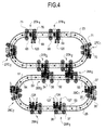
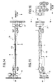
- the sealing section 13 includes a box-like frame 22 and a pair of upper oval tracks 23 and 24 and a pair of lower oval tracks 25 and 26 which are supported by the frame. Referring to Figure 4, a plurality of top die assemblies 27 ride on the upper tracks, and a plurality of bottom die assemblies 28 ride on the lower tracks.
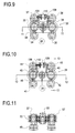
- each of the bottom die assemblies 28 includes an elongated sealing bar 30 which is pivotally mounted on carriages 31 and 32.
- the carriage 32 on the drive side of machine includes a carriage housing 33 ( Figure 9) and four bogie wheels 34-37 which are rotatably mounted on a pair of bogie arms 38 and 39 which are pivotally mounted on the housing.
- the carriage 31 on the operator side of the machine similarly includes a carriage housing 40 ( Figure 10), four bogie wheels 41-44, and a pair of bogie arms 45 and 46.
- Each of the bogie wheels is provided with a V-shaped groove 48 which rides on a V-shaped edge on one of the lower tracks 25 and 26 (see Figures 5 and 8).
- each of the lower tracks includes an inside V-shaped edge 50 and an outside V-shaped edge 51.
- the inside bogie wheels 34, 35, 41, and 42 ride on the inside edges of the tracks, and the outside bogie wheels 36, 37, 43, and 44 ride on the outside edges of the tracks.
- Each of the oval tracks includes a pair of upper and lower parallel horizontal straight portions 52 and 53 and a pair of curved arcuate end portions 54 and 55.
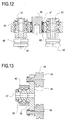
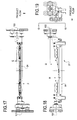
- Each of the bogie arms 38, 39, 45 and 46 includes a center mounting shaft 57 (Figure 13) which is pivotally mounted in two bearings 58 and 59 in the carriage housing. As shown in Figure 4, the pivotable bogie arms pivot as the carriages travel around the curved end portions of the tracks so that all four bogie wheels ride securely on the track.
- a carriage bearing shaft 60 ( Figure 12) is pivotally mounted in the center of the carriage by two bearings 61 and 62.
- each of the top die assemblies 27 includes an elongated sealing bar 64 which is pivotally mounted in carriages 65 and 66.
- the carriages 65 and 66 are similar to the carriages 31 and 32.
- Carriage 65 includes carriage housing 67 and grooved bogie wheels 68-71 which are mounted on pivotable bogie arms 72 and 73.
- Carriage 66 includes carriage housing 74 and bogie wheels 75-78 which are mounted on bogie arms 79 and 80.
- Each bogie arm is pivotally mounted in two bearings in the carriage housing.
- a carriage bearing shaft 90 is pivotally mounted in the center of the housing by two bearings 91.
- the inside bogie wheels 68, 69, 75 and 76 ride on the inside V-shaped edges of the upper tracks 23 and 24 and the outside bogie wheels 70, 71, 77 and 78 ride on the outside V-shaped edges of the upper tracks.
- the sealing bar 30 of each of the bottom die assemblies includes a pair of end mounting brackets 92 and 93 ( Figure 5) which are secured to the bearing shafts 60 of the carriages 31 and 32. Although the shafts 60 are rotatably mounted in the carriage housings, the sealing bar cannot rotate because the carriages are offset both horizontally and vertically.
- the pivot points 95 and 96 of the shafts 60 of the carriages 31 and 32 are offset in the horizontal direction or in the direction of product flow relative to the center of gravity CG of the die assembly by the dimensions A and B, respectively.
- the pivot points are offset in the vertical direction by the dimensions C and D.
- the distance between the V grooves in the bogie wheels on each end of the die assembly was 40.06 inches, the dimensions A and B were both 1.5 inches for a total horizontal offset of 3.0 inches, and the dimensions C and D were 2.25 and 0.75 inches for a total vertical offset of 3.0 inches.
- the sealing bar 64 of each of the top die assemblies 27 is similarly pivotally secured to the carriage bearing shafts 90 by end brackets 98 and 99 ( Figure 5).
- the pivot points 100 and 101 ( Figures 17 and 18) of the carriage bearing shafts 90 are offset horizontally from the center of gravity CG of the die assembly by dimensions E and F and are offset vertically by dimensions G and H.
- the distance between the V grooves of the bogie wheels was 40.06 inches
- the dimensions E and F were both 1.50 inches for a total horizontal offset of 3.0 inches
- the dimensions G and H were 4.50 and 1.50 inches for a vertical offset of 3.0 inches.
- the two upper tracks 23 and 24 are offset horizontally and vertically by the same amount as the offsets of the carriages for the upper die assembly.
- the two lower tracks 25 and 26 are similarly offset horizontally and vertically.
- Figure 20 illustrates top die assemblies 27A and 27B traveling around upper tracks 23 and 24.
- the relative positions of carriages 65A and 66A and carriages 65B and 66B are maintained throughout the path of travel, and the sealing bars 64A and 64B are thereby always maintained in a vertical position.
- the lower sealing bars 30 are likewise maintained in vertical position as they travel around the lower tracks.
- top die assemblies 27A 1 and 27A 2 , 27B 1 , and 27B 2 , and 27C 1 and 27C 2 are mounted on the upper tracks 23 and 24.
- Each pair of die assemblies is independently driven by one of three top drive belts 105A, 105B, and 105C ( Figure 2) on each side of the sealing section.
- a drive shaft 106 is attached to each of the drive belts by a connector 107.
- Each of the drive shafts is connected to one of the carriages by a drive shaft housing 108 ( Figures 9 and 10) which is secured to the carriage housing.
- the drive shaft is inserted into a notch 109 in the drive shaft housing and is secured by a cap 110 which is screwed onto the housing.
- Each pair of drive belts 105A, 105B, and 105C is driven by a separate servo motor 112A, 112B, and 112C ( Figures 1 and 2) so that each pair of die assemblies 27A, 27B, and 27C can be driven independently.
- three pairs of bottom die assemblies 28A 1 and 28A 2 , 28B 1 , and 28B 2 , and 28C 1 , and 28C 2 are mounted on the lower tracks 25 and 26 and are driven by bottom drive belts 114A, 114B, and 114C and drive shafts 115 ( Figure 2).
- the pairs 28A, 28B, and 28C of bottom die assemblies are driven by the servo motors 112A, 112B, and 112C, respectively.
- top and bottom dies 27A and 28A are driven by the same servo motor 112A. The movement of those dies is therefore coordinated, and a top die 27A meets a bottom die 28A as those dies move around the left curved ends of the tracks and approach the horizontal portions of the tracks. Similarly, the top and bottom dies 27B, 27C and 28B, 28C are driven by common servos 112B and 112C, respectively.
- the preferred sealing mechanism is illustrated in Figure 6.
- An electrical resistance sealing ribbon 120 is mounted on each of the top sealing bars 64.
- the ribbon includes a pair of flat side portions 121 and a central projection 122 which projects beyond the plane of the side portions.
- a compressible and resilient silicone pad 124 is mounted on each of the bottom sealing bars 30.
- a pair of gripper plates 125 extend downwardly from the top sealing bar and are engageable with compressible and resilient gripper pads 126 on the bottom sealing bar.
- Each of the bottom sealing bars also includes a pair of upwardly extending, elongated prongs 127 ( Figure 4).
- the specific sealing ribbon 120 illustrated in Figures 6 and 6A is available from Toss Machine Components of Nazareth, Pennsylvania.
- the ribbon is heated by electric current in order to seal and sever the two layers formed by the plastic film.
- the prongs 127 and the bottom sealing bar serve to guide the top sealing bar.
- the film is held by gripper plates 125 on the upper sealing bar which push the film against the gripper pads 126.
- the heated sealing ribbon 120 clamps the film against the pad 124, the top and bottom layers of the film are fused.
- the central projection 122 severs the layers of film between the fused portions.
- the sealing bars 27 and 28 seal the film over a very short dimension in the direction of product flow and simultaneously sever the film.
- the sealing dies therefore require less film for sealing and severing the film than the sealing and cutoff dies of U.S. Patent No. 5,433,063.
- the sealing dies 27 and 28 are also much lighter and have less inertia than prior dies. The new sealing dies can therefore moved faster around the tracks.
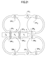
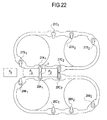
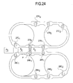
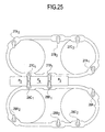
- Figures 21-25 illustrate the sequence of the sealing operation.
- Figure 21 illustrates upper and lower dies 27A 1 and 28A 1 coming together and collapsing the tube of film F behind product P 2 and beginning to push the product P 2 through the sealing section. The film has already been sealed around product P 1 in the previous cycle.
- Figure 22 shows the dies 27A 1 and 28A 1 at the beginning of the sealing cycle where the film tube F has been impinged between the upper and lower dies and the dies continue to push the product P2 through the sealing section.
- a new product P 3 moves in behind the dies 27A 1 and 28A 1 .
- FIG 24 the sealing and cutting process of dies 27A 1 and 28A 1 is completed.
- the dies 27A 1 and 28A 1 are ready to be accelerated away from the product P 3 .
- the dies 27A 2 and 28A 2 are driven by the same drive belt as the dies 27A 1 and 28A 1 , respectively, and will be accelerated toward the new product to be in position to collapse the tube of film on a new product.
- the completely sealed and cut package P 2 is discharged out of the sealing section.
- Dies 27B 1 and 28B 1 are in the process of sealing the film behind product P 3 .
- Dies 27C 1 and 28C 1 collapse the film tube behind the product P 4 .
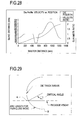
- Figures 26-28 compare the motion profiles of the prior art dies described in U.S. Patent No. 5,433,063 and the dies of this invention.
- the velocity of the dies is equal to the film velocity as the die halves make contact with the film. The die halves then slow down to collapse the film between the products. As each die continues around the radius of the pulley, it begins to accelerate back to film velocity. Each die half, with a product in front of it, will travel at film velocity until the next die half touches the film. Then the first die half will decelerate to allow the next die half to collapse the film tube. After that die half finishes collapsing the film tube, both will accelerate back to film velocity.
- the new profile illustrated in figure 27 is first developed as a quadratic profile with the eventual conversion to cubic motion as a major consideration.
- the previous art illustrated in Figure 26 divided all speed up or slow down moves into standard trapezoidal motion where the master distance is evenly divided by three.
- the new profile calculations attempt to divide the moves evenly in two with the realization that the peak changes of acceleration will be smoothed out with the cubic motion conversion.
- Sometimes, however, a maximum or minimum velocity will force the addition of a third segment. The die during this segment will travel at this velocity limit for the minimum distance necessary and then resume acceleration. This keeps the acceleration rates at a minimum while remaining within velocity limits.
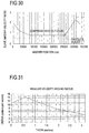
- Figure 29 illustrates the arcuate end portion of one of the upper tracks and the height of the package and the film tube.
- the upper die first touches the film at point A and must decelerate from film velocity to product velocity in the distance from point A until the die reaches bottom-dead-center on the arcuate end portion of the track at point B.
- the angle between points A and B is referred to as the critical angle.
- the arc length that the die travels over the critical angle is the critical angle distance.
- the path of the lower die is the mirror image of the path of the upper die.
- the lower die contacts the bottom of the film tube as the lower die moves upwardly along the arcuate end portion of the lower track and decelerates until the lower die reaches the top-dead-center position on the radius of the arcuate portion of the track.
- the die half As the upper die half reaches the bottom of the radius, it approaches the package velocity. The die half will continue to travel at the package velocity for the distance specified as the seal distance. During this part of the travel, the package will be sealed and cut from the continuous tube of film. After the seal distance, the die half will accelerate to travel the remaining distance of the track to be in position for the next product.
- the motion profile provides a continuous change in deceleration of the die half through the critical angle distance. This motion provides for a smoother collapse of the film tube and transition into the seal distance.
- the invention provides an in-line gusseted trim seal style package and provides higher operating speeds, film savings, and additional area on the end panel to print advertising.
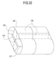
- Figure 32 illustrates a package 125 of four rolls 126 of bathroom tissue. The ends of the package are closed by gussets 127 and 128 and sealed by trim seals 129.
Landscapes
- Engineering & Computer Science (AREA)
- Mechanical Engineering (AREA)
- Package Closures (AREA)
- Closing Of Containers (AREA)
Applications Claiming Priority (2)
| Application Number | Priority Date | Filing Date | Title |
|---|---|---|---|
| US579104 | 2000-05-25 | ||
| US09/579,104 US6408600B1 (en) | 2000-05-25 | 2000-05-25 | Wrapping apparatus and process |
Publications (1)
| Publication Number | Publication Date |
|---|---|
| EP1157930A2 true EP1157930A2 (de) | 2001-11-28 |
Family
ID=24315571
Family Applications (1)
| Application Number | Title | Priority Date | Filing Date |
|---|---|---|---|
| EP01110234A Withdrawn EP1157930A2 (de) | 2000-05-25 | 2001-04-25 | Vorrichtung und Verfahren zum Versiegeln für eine Verpackungsmaschine |
Country Status (6)
| Country | Link |
|---|---|
| US (1) | US6408600B1 (de) |
| EP (1) | EP1157930A2 (de) |
| JP (1) | JP2002002625A (de) |
| BR (1) | BR0101166A (de) |
| CA (1) | CA2338904A1 (de) |
| DE (1) | DE1157930T1 (de) |
Cited By (4)
| Publication number | Priority date | Publication date | Assignee | Title |
|---|---|---|---|---|
| EP1442984A1 (de) * | 2003-01-31 | 2004-08-04 | KPL Packaging S.p.A. | Verpackungsmaschine zum Einhüllen von Gegenständen in jeweils einer Folie aus heisssiegelbarem Verpackungsmaterial |
| EP2983994A4 (de) * | 2013-04-08 | 2016-12-21 | Alain Cerf | Mehrere siegelbacken zum umhüllen mit plastikfolie |
| ITUB20152063A1 (it) * | 2015-07-10 | 2017-01-10 | Cps Company S R L | Macchina avvolgitrice di prodotti singoli o raggruppati e/od impilati, in confezioni di materia termoplastica ricavate da film svolto da bobina e relativo procedimento di lavoro |
| US20210269182A1 (en) * | 2018-06-29 | 2021-09-02 | Sealed Air Corporation (Us) | End seal carriage velocity differential |
Families Citing this family (15)
| Publication number | Priority date | Publication date | Assignee | Title |
|---|---|---|---|---|
| KR20030016135A (ko) * | 2001-08-23 | 2003-02-26 | 김은갑 | 포장기계의 직구동 시스템 |
| ITBO20020392A1 (it) * | 2002-06-18 | 2003-12-18 | Tmc Spa | Metodo ed apparato per il confezionamento di pacchi di rotoli di carta con relativa impugnatura di presa |
| ITBO20030710A1 (it) * | 2003-11-24 | 2005-05-25 | Gd Spa | Macchina e metodo per realizzare una confezione ripiegando |
| EP1535843B1 (de) * | 2003-11-28 | 2007-10-10 | KPL Packaging S.p.A. | Verpackungsmaschine für die Produktumwicklung in korrespondierenden Zuschnitten aus heisssiegelbarem Umwicklungsmaterial |
| DE102011117165A1 (de) * | 2011-05-03 | 2012-11-08 | Khs Gmbh | Verfahren und Vorrichtung zum Verpacken von zu Verpackungseinheiten zusammengefassten Gruppen an Gegenständen |
| US20130097965A1 (en) * | 2011-10-21 | 2013-04-25 | Rethceif Enterprises, Llc | Apparatus for forming elongate plastic film into a tube around variable size articles |
| ES2436535B1 (es) * | 2013-07-12 | 2014-10-08 | Ulma Packaging Technological Center, S.Coop. | Máquina envolvedora de productos y método de operación para una máquina envolvedora de productos |
| EP3254980B1 (de) * | 2016-06-09 | 2018-12-19 | Tetra Laval Holdings & Finance S.A. | Verpackungsvorrichtung zur formung versiegelter pakete aus schlauchförmigem verpackungsmaterial |
| JP6756762B2 (ja) * | 2018-03-28 | 2020-09-16 | 大王製紙株式会社 | 包装袋 |
| US11565844B2 (en) | 2018-12-21 | 2023-01-31 | S.C. Johnson & Son, Inc. | Methods and apparatus to facilitate plastic film processing |
| US10843828B2 (en) | 2019-01-22 | 2020-11-24 | Paper Converting Maching Company | Packaging method and line for improved finished product |
| US11225343B2 (en) | 2019-01-22 | 2022-01-18 | Paper Converting Maching Company | Packaging method and line for improved finished product |
| IT201900013770A1 (it) * | 2019-08-02 | 2021-02-02 | Plusline S R L | Macchina per il confezionamento di rotoli di carta. |
| FI4007724T3 (fi) * | 2019-08-02 | 2023-06-08 | Plusline S R L | Pakkauskone paperirullien pakkaamiseksi |
| IT202000000562A1 (it) * | 2020-01-14 | 2021-07-14 | Plusline S R L | Macchina per il confezionamento di prodotti come rotoli di carta. |
Citations (8)
| Publication number | Priority date | Publication date | Assignee | Title |
|---|---|---|---|---|
| US143455A (en) | 1873-10-07 | Improvement in machines for splitting wood | ||
| US147153A (en) | 1874-02-03 | Improvement in sewing-machines | ||
| US4430844A (en) | 1981-04-27 | 1984-02-14 | Hayssen Manufacturing Company | Method of and apparatus for wrapping articles |
| US5228273A (en) | 1990-10-04 | 1993-07-20 | Hayssen Manufacturing Co. | Method of and apparatus for making packages |
| US5255495A (en) | 1992-10-30 | 1993-10-26 | Hayssen Manufacturing Company | Adjustable girth former |
| US5433069A (en) | 1991-12-02 | 1995-07-18 | Fluor Corporation | Process and economic use of excess compressed air when firing low BTU gas in a combustion gas turbine |
| US5433063A (en) | 1993-04-29 | 1995-07-18 | Hayssen Manufacturing Company | Sealing system and process for packaging machine |
| US5799467A (en) | 1997-05-19 | 1998-09-01 | Paper Converting Machine Company | Breathable girth unit for a tube former in a packaging apparatus and method |
Family Cites Families (8)
| Publication number | Priority date | Publication date | Assignee | Title |
|---|---|---|---|---|
| US3815313A (en) * | 1972-10-04 | 1974-06-11 | R Heisler | Apparatus and method for automatically sizing and wrapping a shrink wrap envelope around advancing luggage |
| CH573326A5 (de) * | 1974-01-24 | 1976-03-15 | Sig Schweiz Industrieges | |
| JPS6011347A (ja) * | 1983-06-30 | 1985-01-21 | 株式会社古川製作所 | 製袋方法およびその装置 |
| US4765474A (en) | 1987-02-19 | 1988-08-23 | Hayssen Manufacturing Company | Package of enwrapped articles |
| JPH03124506A (ja) * | 1989-10-09 | 1991-05-28 | Ibaraki Seiki Kk | 包装機における袋へのガス供給装置 |
| US5302227A (en) * | 1992-03-20 | 1994-04-12 | Kliklok Corporation | Method for closing a heat-resistant carton |
| US5220771A (en) * | 1992-04-14 | 1993-06-22 | Milliken Research Corporation | Tetrahedron volume control |
| US5406887A (en) | 1993-01-15 | 1995-04-18 | Paper Converting Machine Company | Apparatus and method for doctor blade replacement in a flexographic press |
-
2000
- 2000-05-25 US US09/579,104 patent/US6408600B1/en not_active Expired - Lifetime
-
2001
- 2001-02-28 CA CA002338904A patent/CA2338904A1/en not_active Abandoned
- 2001-03-27 BR BR0101166-9A patent/BR0101166A/pt not_active Application Discontinuation
- 2001-04-25 EP EP01110234A patent/EP1157930A2/de not_active Withdrawn
- 2001-04-25 DE DE1157930T patent/DE1157930T1/de active Pending
- 2001-05-16 JP JP2001146660A patent/JP2002002625A/ja not_active Withdrawn
Patent Citations (8)
| Publication number | Priority date | Publication date | Assignee | Title |
|---|---|---|---|---|
| US143455A (en) | 1873-10-07 | Improvement in machines for splitting wood | ||
| US147153A (en) | 1874-02-03 | Improvement in sewing-machines | ||
| US4430844A (en) | 1981-04-27 | 1984-02-14 | Hayssen Manufacturing Company | Method of and apparatus for wrapping articles |
| US5228273A (en) | 1990-10-04 | 1993-07-20 | Hayssen Manufacturing Co. | Method of and apparatus for making packages |
| US5433069A (en) | 1991-12-02 | 1995-07-18 | Fluor Corporation | Process and economic use of excess compressed air when firing low BTU gas in a combustion gas turbine |
| US5255495A (en) | 1992-10-30 | 1993-10-26 | Hayssen Manufacturing Company | Adjustable girth former |
| US5433063A (en) | 1993-04-29 | 1995-07-18 | Hayssen Manufacturing Company | Sealing system and process for packaging machine |
| US5799467A (en) | 1997-05-19 | 1998-09-01 | Paper Converting Machine Company | Breathable girth unit for a tube former in a packaging apparatus and method |
Cited By (7)
| Publication number | Priority date | Publication date | Assignee | Title |
|---|---|---|---|---|
| EP1442984A1 (de) * | 2003-01-31 | 2004-08-04 | KPL Packaging S.p.A. | Verpackungsmaschine zum Einhüllen von Gegenständen in jeweils einer Folie aus heisssiegelbarem Verpackungsmaterial |
| US6907716B2 (en) | 2003-01-31 | 2005-06-21 | Kpl Packaging S.P.A. | Packaging machine for wrapping products in respective sheets of heat-seal wrapping material |
| EP2983994A4 (de) * | 2013-04-08 | 2016-12-21 | Alain Cerf | Mehrere siegelbacken zum umhüllen mit plastikfolie |
| ITUB20152063A1 (it) * | 2015-07-10 | 2017-01-10 | Cps Company S R L | Macchina avvolgitrice di prodotti singoli o raggruppati e/od impilati, in confezioni di materia termoplastica ricavate da film svolto da bobina e relativo procedimento di lavoro |
| WO2017009737A1 (en) * | 2015-07-10 | 2017-01-19 | Cps Company S.R.L. | Wrapping machine for single or grouped and/or stacked products, in packs of thermoplastic material obtained from film unwound from a reel and related operating method |
| US20210269182A1 (en) * | 2018-06-29 | 2021-09-02 | Sealed Air Corporation (Us) | End seal carriage velocity differential |
| US12157597B2 (en) * | 2018-06-29 | 2024-12-03 | Sealed Air Corporation (Us) | End seal carriage velocity differential |
Also Published As
| Publication number | Publication date |
|---|---|
| US6408600B1 (en) | 2002-06-25 |
| JP2002002625A (ja) | 2002-01-09 |
| BR0101166A (pt) | 2002-01-02 |
| DE1157930T1 (de) | 2003-03-06 |
| CA2338904A1 (en) | 2001-11-25 |
Similar Documents
| Publication | Publication Date | Title |
|---|---|---|
| US6408600B1 (en) | Wrapping apparatus and process | |
| US4711065A (en) | Apparatus for producing packs, especially cigarette cartons | |
| EP0691916B1 (de) | Verfahren zum gruppenweisen verpacken von gengenständen | |
| EP3414167B1 (de) | Verpackungsverfahren und -maschine in dehnbarer folie von in gruppen zugeführten produkten | |
| US6817163B2 (en) | Film delivery unit for shrink wrap packaging system and associated method | |
| US10427886B2 (en) | Apparatus and process for rotating products | |
| GB2139175A (en) | A machine for packing continuously moving articles with a strip of heat-shrinkable material | |
| JP2723273B2 (ja) | カラーを有するヒンジ蓋付き・煙草パッケージの製造装置 | |
| US20020000400A1 (en) | Device for removal of trimmings in the production of rolls of web material | |
| JPH03114739A (ja) | 紙ナプキンまたは同様な物品を製造するための装置及び方法 | |
| JPS6112566A (ja) | スタック形成及び送出し装置 | |
| BR112018015176A2 (en) | method and packaging machine of extensible film of product groups. | |
| CN106628382A (zh) | 一种面膜的生产包装设备 | |
| US5269122A (en) | Apparatus and method for forming protective packages | |
| US5845464A (en) | Product wrapping method | |
| US7398630B2 (en) | Infeed assembly for a continuous motion wrapping assembly | |
| CN113490579B (zh) | 用于对纸卷进行封装的系统和操作方法 | |
| US7610737B2 (en) | Continuous motion wrapping method | |
| AU2003262105B2 (en) | Method and device for the packaging of flat objects | |
| JP2022529598A (ja) | 包装機においてプラスチックフィルムを供給するための供給ユニット | |
| KR101625541B1 (ko) | 제품을 포장하기 위한 방법 및 이 방법을 실시하기 위한 포장 장치 | |
| MXPA01005277A (en) | Sealing apparatus and method for packaging machine | |
| EP0728668A1 (de) | Siegelvorrichtung und -verfahren für eine Verpackungsmaschine | |
| CN206243589U (zh) | 一种面膜的生产包装设备 | |
| ITTO20000979A1 (it) | Macchina confezionatrice automatica e procedimento per il confezionamento di prodotti. |
Legal Events
| Date | Code | Title | Description |
|---|---|---|---|
| PUAI | Public reference made under article 153(3) epc to a published international application that has entered the european phase |
Free format text: ORIGINAL CODE: 0009012 |
|
| AK | Designated contracting states |
Kind code of ref document: A2 Designated state(s): AT BE CH CY DE DK ES FI FR GB GR IE IT LI LU MC NL PT SE TR |
|
| AX | Request for extension of the european patent |
Free format text: AL;LT;LV;MK;RO;SI |
|
| STAA | Information on the status of an ep patent application or granted ep patent |
Free format text: STATUS: THE APPLICATION HAS BEEN WITHDRAWN |
|
| DET | De: translation of patent claims | ||
| 18W | Application withdrawn |
Effective date: 20030124 |