EP1157855A1 - Gummizylinderhülse, insbesondere für Offset-Rollenrotationsdruckmaschinen - Google Patents
Gummizylinderhülse, insbesondere für Offset-Rollenrotationsdruckmaschinen Download PDFInfo
- Publication number
- EP1157855A1 EP1157855A1 EP01112326A EP01112326A EP1157855A1 EP 1157855 A1 EP1157855 A1 EP 1157855A1 EP 01112326 A EP01112326 A EP 01112326A EP 01112326 A EP01112326 A EP 01112326A EP 1157855 A1 EP1157855 A1 EP 1157855A1
- Authority
- EP
- European Patent Office
- Prior art keywords
- joint
- sleeve
- layer
- rubber cylinder
- cylinder sleeve
- Prior art date
- Legal status (The legal status is an assumption and is not a legal conclusion. Google has not performed a legal analysis and makes no representation as to the accuracy of the status listed.)
- Granted
Links
- 229920001971 elastomer Polymers 0.000 title claims description 42
- 238000007645 offset printing Methods 0.000 title claims description 5
- 239000000463 material Substances 0.000 claims abstract description 14
- 238000007639 printing Methods 0.000 claims description 17
- 229910052751 metal Inorganic materials 0.000 claims description 9
- 239000002184 metal Substances 0.000 claims description 9
- 210000001503 joint Anatomy 0.000 description 6
- 238000005096 rolling process Methods 0.000 description 6
- 238000004519 manufacturing process Methods 0.000 description 5
- 229910000831 Steel Inorganic materials 0.000 description 3
- 239000013536 elastomeric material Substances 0.000 description 3
- 238000000034 method Methods 0.000 description 3
- 239000010959 steel Substances 0.000 description 3
- PXHVJJICTQNCMI-UHFFFAOYSA-N Nickel Chemical compound [Ni] PXHVJJICTQNCMI-UHFFFAOYSA-N 0.000 description 2
- 239000000853 adhesive Substances 0.000 description 2
- 238000004026 adhesive bonding Methods 0.000 description 2
- 230000001070 adhesive effect Effects 0.000 description 2
- 239000000806 elastomer Substances 0.000 description 2
- 239000000835 fiber Substances 0.000 description 2
- 229920001875 Ebonite Polymers 0.000 description 1
- 230000002411 adverse Effects 0.000 description 1
- 229910052782 aluminium Inorganic materials 0.000 description 1
- XAGFODPZIPBFFR-UHFFFAOYSA-N aluminium Chemical compound [Al] XAGFODPZIPBFFR-UHFFFAOYSA-N 0.000 description 1
- 230000009286 beneficial effect Effects 0.000 description 1
- 239000004918 carbon fiber reinforced polymer Substances 0.000 description 1
- 238000010276 construction Methods 0.000 description 1
- 238000011161 development Methods 0.000 description 1
- 230000018109 developmental process Effects 0.000 description 1
- 230000000694 effects Effects 0.000 description 1
- 239000013013 elastic material Substances 0.000 description 1
- 238000009408 flooring Methods 0.000 description 1
- 239000003365 glass fiber Substances 0.000 description 1
- 229910052759 nickel Inorganic materials 0.000 description 1
- 239000002245 particle Substances 0.000 description 1
- 239000004033 plastic Substances 0.000 description 1
- 238000003466 welding Methods 0.000 description 1
Images


Classifications
-
- B—PERFORMING OPERATIONS; TRANSPORTING
- B41—PRINTING; LINING MACHINES; TYPEWRITERS; STAMPS
- B41N—PRINTING PLATES OR FOILS; MATERIALS FOR SURFACES USED IN PRINTING MACHINES FOR PRINTING, INKING, DAMPING, OR THE LIKE; PREPARING SUCH SURFACES FOR USE AND CONSERVING THEM
- B41N6/00—Mounting boards; Sleeves Make-ready devices, e.g. underlays, overlays; Attaching by chemical means, e.g. vulcanising
-
- B—PERFORMING OPERATIONS; TRANSPORTING
- B41—PRINTING; LINING MACHINES; TYPEWRITERS; STAMPS
- B41N—PRINTING PLATES OR FOILS; MATERIALS FOR SURFACES USED IN PRINTING MACHINES FOR PRINTING, INKING, DAMPING, OR THE LIKE; PREPARING SUCH SURFACES FOR USE AND CONSERVING THEM
- B41N10/00—Blankets or like coverings; Coverings for wipers for intaglio printing
- B41N10/02—Blanket structure
- B41N10/04—Blanket structure multi-layer
-
- B—PERFORMING OPERATIONS; TRANSPORTING
- B41—PRINTING; LINING MACHINES; TYPEWRITERS; STAMPS
- B41N—PRINTING PLATES OR FOILS; MATERIALS FOR SURFACES USED IN PRINTING MACHINES FOR PRINTING, INKING, DAMPING, OR THE LIKE; PREPARING SUCH SURFACES FOR USE AND CONSERVING THEM
- B41N10/00—Blankets or like coverings; Coverings for wipers for intaglio printing
- B41N10/02—Blanket structure
- B41N10/06—Blanket structure facilitating fastening to, or location on, supports
-
- B—PERFORMING OPERATIONS; TRANSPORTING
- B41—PRINTING; LINING MACHINES; TYPEWRITERS; STAMPS
- B41N—PRINTING PLATES OR FOILS; MATERIALS FOR SURFACES USED IN PRINTING MACHINES FOR PRINTING, INKING, DAMPING, OR THE LIKE; PREPARING SUCH SURFACES FOR USE AND CONSERVING THEM
- B41N10/00—Blankets or like coverings; Coverings for wipers for intaglio printing
- B41N10/02—Blanket structure
-
- B—PERFORMING OPERATIONS; TRANSPORTING
- B41—PRINTING; LINING MACHINES; TYPEWRITERS; STAMPS
- B41N—PRINTING PLATES OR FOILS; MATERIALS FOR SURFACES USED IN PRINTING MACHINES FOR PRINTING, INKING, DAMPING, OR THE LIKE; PREPARING SUCH SURFACES FOR USE AND CONSERVING THEM
- B41N2210/00—Location or type of the layers in multi-layer blankets or like coverings
- B41N2210/02—Top layers
Definitions
- the invention relates to a rubber sleeve according to the preamble of claim 1.
- a similar device is known from DE 196 28 555 A1.
- Such sleeves are, for example, from US Pat. Nos. 5,429,048,5 323 702, 5 440 981 and 5 304 267.
- a disadvantage of this known Rubber cylinder sleeves is that the middle and lower layers of the same must be at least partially continuous. This has a particularly disadvantageous effect on the manufacturing costs.
- the object of the present invention is a generic Rubber cylinder sleeve, especially for offset web-fed rotary printing presses, in Compared to the known sleeves of this type cheaper to manufacture at about same or improved print quality and behavior.
- the task is accomplished through the application of the characteristics of the independent Claim 1 solved.
- the rubber cylinder sleeve is inexpensive to produce. It also enables good print quality because it matches the compressible material filled joint allows tangential forces during the rolling contact with other printing unit cylinders.
- Rubber cylinder sleeves essentially from an inner, preferably metallic sleeve.
- an inner metal sleeve preferably metallic sleeve
- GPP glass fiber reinforced sleeve
- This The thickness of the sleeves is such that they can be pushed onto the Transfer cylinder, which is usually used for indirect printing processes working printing machines is called rubber cylinders, by air slightly can be expanded. This is advantageous because, like that, in particular U.S. Patent 5,429,048 shows such a sleeve through the side wall of a Printing machine on the previously uncovered transfer cylinder can be postponed.
- Transfer cylinder provided openings with the sleeve to be pushed on Compressed air expanded so that application is possible in a simple manner after which the compressed air is removed and the sleeve is firmly seated occupies on the transfer cylinder.
- At least one is on this inner, preferably metallic support sleeve another layer - directly or indirectly - applied, which is compressible, d. i.e., the Has air pockets.
- At least one top layer is over this layer provided, which can for example consist of an elastomeric material.
- a forme cylinder or a printing form for example an offset printing plate or a sleeve-shaped offset printing form, the image to be printed is transferred and transferred to a print carrier.
- the compressible layer e.g. an elastomer with Air pockets
- another non-stretchable layer provided, for example in the form of a hard elastomeric material or for example in the form of short fibers (e.g. threads) that are also in the hard elastomeric material can be embedded.
- stretchable layer or non-stretchable particles, such as threads or pieces Threads introduced directly into the volume compressible layer mentioned above become.
- the transfer cylinder with 1 (blanket cylinder) and the openings or nozzles provided on its surface are designated by 1a.
- the transfer cylinder sleeve 2 applied above (Blanket sleeve) preferably has one, as stated above air-expandable metal sleeve 3 on which a compressible layer 4 vulcanized or glued on.
- On the compressible layer 4 is one Layer of a non-stretchable material 5, preferably a hard one Elastomer layer with short fibers, which are not specified, is provided.
- a cover layer 6 is provided on the non-stretchable layer 5, For example, from an elastic material with the offset printing process can be printed.
- a metal sleeve is preferably used as the carrier sleeve 3 used, for example made of steel, which is expandable by air and the one Has joint 7.
- This joint 7 can for example be a weld be formed in an advantageous manner in that the metallic sleeve is made of a plate whose ends are welded together so that the joint 7 results.
- the carrier sleeve 3 can also be designed to be shock-free and gap-free, in which case then the joint 7 shown in FIG. 1 is omitted. With a metallic Such execution recommends the production by galvanic means. Non-metallic carrier sleeves 3 are advantageously free of bumps and gaps producible.
- a joint is understood in particular to mean that a sleeve or cylindrical rubber or plastic layer or a sleeve or cylindrical metallic or non-metallic carrier in the circumferential direction is not endless, i.e. not seamless or not continuous, i.e. that in longitudinal or Axis direction there is a seam or a joint.
- the joint can have abutting layers. It can also be a gap between represent the ends of a layer, which is advantageous with an adhesive or vulcanizable material is closed.
- the compressible layer 4 also has a joint 8 which can be produced in that the compressible layer on the metal sleeve 3 4 is glued in the form of a rubber blanket, so that the joint 8 through the Ends of the rubber layer 4 are formed.
- a non-stretchable layer 5 on the compressible layer 4 these also have a joint 9 according to the invention, which can be formed in the manner described above.
- such Layer structure d. H. a carrier sleeve 3 preferably made of metal with a Butt joint 7 and at least one compressible layer 4 applied a joint 8, a cover layer 6 applied without a joint.
- cover layer 6 - just like the compressible layer 4 - Has air pockets, so that the cover layer 6 has a certain Compressibility has what is advantageous compared to the prior art and too lead to better printing results or printing behavior and better web guidance can.
- the sleeve according to the invention can also be particularly advantageous in this way be made that a welded metal sleeve 3 made of steel or aluminum or, for example, a CFRP sleeve with a joint is used on the a conventional offset rubber blanket, e.g. B. with a compressible layer, is applied, for example glued or vulcanized or is. After that the top layer of the conventional rubber blanket is removed, for example, sanded and replaced by a continuous, d. H. a shock-free cover layer 6 applied, for example vulcanized.
- Across from the known sleeves is such a manufacture and such Sleeve construction much cheaper and has a number of advantages.
- the joints 8, 9 are one above the other because they are the ends of the conventional blanket, which was glued to the carrier sleeve 3, represent.
- the joints 8, 9 can advantageously - but do not necessarily have to be direct be arranged above the joint 7.
- the individual joints 7, 8, 9 can also be seen circumferentially at others Digits are d. H. they do not have to be on top of one another, as shown.
- the advantageous arrangement of short is not stretchable pieces, such as threads.
- the sleeve 2 according to the invention offers a variety of possible uses not just on the use of offset web-fed rotary presses are limited.
- this sleeve 2 can also be used with others indirect printing processes, such as indirect gravure, are used or as Roller are used.
- a marking on one end of the sleeve and one Transfer cylinder end to be present which coincided with a registration enable, d. H. the sleeve 2 in the manner on the transfer cylinder 1st it can be pushed on that the joints 7, 8, 9 or columns of the tensioning channel 14 a plate cylinder 15 in the rolling area with this opposite, as in the Drawing shown.
- the cover layer 6 can impact or have gap, as indicated at 16. If the gap 16 or the bumps or gaps are relatively large, they can be covered with a suitable material, e.g. an adhesive or vulcanizable material.
- a positive lock for registration provide, for example by means of a on the inner wall of the metal sleeve 3rd attached ledge 3a, which in the assembly of the sleeve 2 in an axially extending Slot 17 of the transfer cylinder 1 can be inserted.
- a special embodiment of the invention is only that Outer layer 6, that is to say the layer receiving the printed image, elastically make, that is, preferably only the lower area or part with z.
- B. Form air pockets or air ducts that may be open at the bottom.
- Such a thing trained layer in which also non-stretch materials, e.g. B. threads or Pieces of thread, can be arranged directly on a carrier sleeve be arranged.
- the layer 3 from fiber-reinforced hard rubber or without seam or gap - the z. B. is stretchable by compressed air, and about this can be a compressible layer, then a semi-compressible layer that can be fiber-reinforced, and then a printing cover layer can be arranged, which is very beneficial.
- the rubber cylinder sleeve 2.1 shown in FIG. 2 is similar in structure to the just described rubber cylinder sleeve according to Figure 1.
- the simplicity for the sake of repetition or similar elements retain the previous reference numerals or add ".1".
- a carrier sleeve 3 is used, the one Has joint 7.
- the carrier sleeve 3 is in this case made of a plate manufactured, the ends of which are welded together so that the joint 7 results.
- the carrier sleeve 3 is advantageously made of steel.
- On the carrier sleeve 3 are a compressible layer 4, an inextensible layer 5 and an outer layer Cover layer 6 arranged. These layers 4, 5, 6 are finite, so not continuously, with a gap remaining between each end.
- the Gaps are arranged over the joint 7 of the carrier sleeve and all of them a compressible material 18 so that each layer 4, 5, 6 one of this compressible material 18 has formed joint 8.1, 9.1, 16.1. It it is also possible that the compressible layer 4 and the non-stretchable layer 5 are continuously executed without a joint and only the joint 16.1 in the outer cover layer 16 is present. There can also be more finite ones or endless layers can be provided.
- the carrier sleeve 3 be carried out continuously, for example as galvanically produced Nickel sleeve.
- the transfer cylinder 1 to which the Rubber cylinder sleeve 2.1 can be pushed on, as well as the rubber cylinder sleeve 2.1 Tools for registration is one of the Inner wall of the carrier sleeve 3 fastened strip 3a, which during the assembly of the Rubber cylinder sleeve 2.1 in an axially extending slot 17 of the Transfer cylinder 1 can be inserted.
- the pushing and pulling of the Rubber cylinder sleeve 2.1 is after their elastic expansion by means of Compressed air supplied to nozzles 1a is possible.
- the width b1 of the joint 16.1 is approximately in the size of the width b of the tensioning channel 14 with the transfer cylinder 1 cooperating plate cylinder 15 dimensioned, practically about 1 to 3mm.
- the rubber cylinder sleeve 2.1 is ins on the transfer cylinder 1 Register brought that their joint 16.1 in the cover layer 6 at Rolling contact with the plate cylinder 15 opposite to its clamping channel 14 comes to lie.
- the joint 16.1 can also be used with a pressure-free one Area B (Fig. 3) of the printed image of a clamped on the plate cylinder 15 Printing form to be brought to cover. For example, at a printing machine with four standing pages in the circumferential direction (so-called double circumference) the area opposite the clamping channel. Through such Registration of the joint 16.1 in the cover layer 6 is avoided that this leads to a loss of printing area.
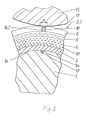
- Figure 3 shows a rubber cylinder sleeve 2.2, in which only the outer Cover layer 6 has a joint 16.2, while the compressible layer 4 and the inextensible layer 5 without an abutment, that is to say endlessly.
- the cover layer 6 is advantageously a plate on the non-stretchable layer 5 brought, e.g. B. glued, the later joint 16.2 forming ends Contain air bubbles 10 and are vulcanized together.
- the carrier sleeve 3 is executed bumpless.
Landscapes
- Printing Plates And Materials Therefor (AREA)
Abstract
Description
- Fig. 1:
- teilweise einen Transferzylinder mit Gummituchhülse und einen Plattenzylinder im Querschnitt
- Fig. 2:
- eine weitere Variante zu Figur 1
- Fig. 3:
- eine dritte Variante zu Figur 1.
Claims (10)
- Gummizylinderhülse (2.1, 2.2) (Transferzylinderhülse), insbesondere für Offset-Druckmaschinen, mit einer durch Luft aufweitbaren inneren Trägerhülse (3), mindestens einer darüberliegend angeordneten kompressiblen Schicht (4) und einer äußeren Deckschicht (6), wobei die Deckschicht (6) als eine endliche, eine Stoßstelle (16.1, 16.2) aufweisende Schicht ausgeführt ist und die Stoßstelle (16.1, 16.2) mit einem kompressiblen Material (18) ausgefüllt ist.
- Gummizylinderhülse nach Anspruch 1, dadurch gekennzeichnet, dass die kompressible Schicht (4) nicht dehnbar ist und/oder über letzterer eine nicht dehnbare Schicht (5) angeordnet ist.
- Gummizylinderhülse nach Anspruch 1 oder 2, dadurch gekennzeichnet, dass alle auf der Trägerhülse (3) angeordneten Schichten (4, 5, 6) endlich mit jeweils einem Stoßstelle (8.1, 9.1, 16.1) ausgeführt sind, wobei die Stoßstellen (8.1, 9.1, 16.1) übereinander liegen und mit dem kompressiblen Material (18) ausgefüllt sind.
- Gummizylinderhülse nach einem der Ansprüche 1 bis 3, dadurch gekennzeichnet, dass das die Stoßstelle ausfüllende Material (18) Luftblasen (10) enthält.
- Gummizylinderhülse nach einem der Ansprüche 1 bis 3, dadurch gekennzeichnet, dass die an der Stoßstelle (16.1) beteiligten Enden der Deckschicht (6) Luftblasen (10) enthalten und aneinander vulkanisiert sind.
- Gummizylinderhülse nach einem der vorherigen Ansprüche, dadurch gekennzeichnet, dass die Trägerhülse (3) als Metallhülse ausgeführt ist, die eine von einer Schweißnaht gebildete Stoßstelle (7) aufweist, wobei die Stoßstelle bzw. die Stoßstellen (8.1, 9.1, 16.1) der auf der Trägerhülse (3) befindlichen Schichten (4, 5, 6) über der Stoßstelle (7) der Trägerhülse (3) angeordnet sind.
- Gummizylinderhülse nach einem der vorherigen Ansprüche, dadurch gekennzeichnet, dass die Gummizylinderhülse (2.1) und ein letztere tragender Transferzylinder (1) Hilfsmittel (3a, 17) für eine Registerung aufweisen.
- Gummizylinderhülse nach einem der Ansprüche 1 bis 7, dadurch gekennzeichnet, dass die Stoßstelle (16.1) in der Deckschicht (6) beim Abrollkontakt der Gummizylinderhülse (2.1) mit einem Plattenzylinder (15) gegenüber von dessen Spannkanal (14) zu liegen kommen.
- Gummizylinderhülse nach Anspruch 8, dadurch gekennzeichnet, dass die Stoßstelle (16.1) etwa die Breite (b) des Spannkanals (14) aufweist.
- Gummizylinderhülse nach einem der Ansprüche 1 bis 7, dadurch gekennzeichnet, dass die Stoßstelle (16.2) in der Deckschicht (6) beim Abrollkontakt der Gummizylinderhülse (2.1) mit einem Plattenzylinder (15) gegenüber von einem druckfreien Bereich B des Druckbildes einer auf den Plattenzylinder (15) gespannten Druckform (19) zu liegen kommt.
Applications Claiming Priority (2)
| Application Number | Priority Date | Filing Date | Title |
|---|---|---|---|
| DE10025374 | 2000-05-23 | ||
| DE10025374A DE10025374A1 (de) | 2000-05-23 | 2000-05-23 | Gummizylinderhülse, insbesondere für Offset-Rollenrotationsdruckmaschinen |
Publications (2)
| Publication Number | Publication Date |
|---|---|
| EP1157855A1 true EP1157855A1 (de) | 2001-11-28 |
| EP1157855B1 EP1157855B1 (de) | 2007-08-01 |
Family
ID=7643159
Family Applications (1)
| Application Number | Title | Priority Date | Filing Date |
|---|---|---|---|
| EP01112326A Expired - Lifetime EP1157855B1 (de) | 2000-05-23 | 2001-05-19 | Gummizylinderhülse, insbesondere für Offset-Rollenrotationsdruckmaschinen |
Country Status (4)
| Country | Link |
|---|---|
| US (1) | US6484632B2 (de) |
| EP (1) | EP1157855B1 (de) |
| JP (1) | JP3442372B2 (de) |
| DE (2) | DE10025374A1 (de) |
Cited By (2)
| Publication number | Priority date | Publication date | Assignee | Title |
|---|---|---|---|---|
| EP1832436A3 (de) * | 2006-03-09 | 2008-03-26 | MAN Roland Druckmaschinen AG | Gummisleeve und Verfahren zur Herstellung desselben |
| EP1832419A3 (de) * | 2006-03-07 | 2009-12-23 | WIFAG Maschinenfabrik AG | Entlastungselement |
Families Citing this family (18)
| Publication number | Priority date | Publication date | Assignee | Title |
|---|---|---|---|---|
| US20110045267A1 (en) * | 1999-10-13 | 2011-02-24 | Hatec Produktions- und Handels- gesellschaft mbH | Substructure material for a printing device and printer's blanket for the printing of uneven materials to be printed |
| EP1224076A4 (de) * | 1999-10-15 | 2006-07-05 | Mlp U S A Inc | Hülsenförmiges drucktuch mit einer naht und dessen verfahren zur herstellung und anwendung |
| US6899029B2 (en) * | 2002-02-14 | 2005-05-31 | Reeves, S.P.A. | Multi-layered gapped cylindrical printing blanket |
| US6851362B2 (en) * | 2002-03-22 | 2005-02-08 | Goss International Americas, Inc. | Printing cylinder with fanout compensation |
| DE10228686A1 (de) * | 2002-06-27 | 2004-02-12 | Man Roland Druckmaschinen Ag | Gummizylinderhülse für Offset-Druckmaschinen |
| DE10241800B4 (de) * | 2002-09-06 | 2014-04-30 | Polywest Kunststofftechnik Saueressig & Partner Gmbh & Co. Kg | Hülse mit mehrschichtigem Aufbau für Druckmaschinen und Verfahren zu ihrer Herstellung |
| US6799511B2 (en) * | 2002-12-03 | 2004-10-05 | Day International, Inc. | Gapless compressible cylinder assembly |
| US7115084B2 (en) * | 2002-12-13 | 2006-10-03 | Eastman Kodak Company | Replaceable fuser member |
| DE602004020612D1 (de) * | 2003-06-09 | 2009-05-28 | Goss Internat Inc | Offsetdruckmaschine mit freitragenden druck- und einfärbemodulen |
| DE102004043088A1 (de) * | 2004-09-07 | 2006-03-09 | Man Roland Druckmaschinen Ag | Sleeve für einen Druckmaschinenzylinder sowie Druckmaschinenzylinder |
| US7422840B2 (en) * | 2004-11-12 | 2008-09-09 | E.I. Du Pont De Nemours And Company | Apparatus and process for forming a printing form having a cylindrical support |
| DE102005013424A1 (de) * | 2005-03-21 | 2006-09-28 | Man Roland Druckmaschinen Ag | Gummisleeve |
| DE102007009810A1 (de) * | 2007-02-28 | 2008-09-04 | Man Roland Druckmaschinen Ag | Übertragungsform für einen Übertragungszylinder einer Druckmaschine |
| DE102007047172A1 (de) | 2007-10-02 | 2009-04-09 | Manroland Ag | Gummisleeve |
| EP2207684B1 (de) * | 2007-10-19 | 2011-11-23 | KHS GmbH | Vorrichtung zum bedrucken von flaschen oder dergleichen behältern an der behälteraussenfläche |
| JP2010184806A (ja) * | 2009-02-13 | 2010-08-26 | Seiko Epson Corp | 搬送ローラー、搬送ユニット、及び印刷装置 |
| JP5402054B2 (ja) * | 2009-02-13 | 2014-01-29 | セイコーエプソン株式会社 | 搬送ローラー、搬送ユニット、及び印刷装置 |
| CN105644135B (zh) * | 2016-02-02 | 2018-01-12 | 京东方科技集团股份有限公司 | 转印设备和涂布机 |
Citations (5)
| Publication number | Priority date | Publication date | Assignee | Title |
|---|---|---|---|---|
| US4125073A (en) * | 1977-11-09 | 1978-11-14 | Rockwell International Corporation | Impact damping of printing cylinders |
| DE3512776A1 (de) * | 1985-04-10 | 1986-10-16 | Wolfgang 6450 Hanau Postel | Druckwalze |
| EP0571909A2 (de) * | 1992-05-29 | 1993-12-01 | MAN Roland Druckmaschinen AG | Offset-Gummituch |
| EP0819550A2 (de) * | 1996-07-16 | 1998-01-21 | MAN Roland Druckmaschinen AG | Gummizylinderhülse, insbesondere für Offset-Rollenrotationsdruckmaschinen |
| DE19950643A1 (de) * | 1999-10-20 | 2001-04-26 | Roland Man Druckmasch | Gummizylinderhülse, insbesondere für Offset-Rollenrotationsdruckmaschinen |
Family Cites Families (7)
| Publication number | Priority date | Publication date | Assignee | Title |
|---|---|---|---|---|
| US5429048A (en) | 1989-10-05 | 1995-07-04 | Gaffney; John M. | Offset lithographic printing press |
| US5553541A (en) | 1989-10-05 | 1996-09-10 | Heidelberg Harris Inc | Gapless tubular printing blanket |
| CA2068629C (en) | 1991-05-14 | 1996-05-07 | James B. Vrotacoe | Gapless tubular printing blanket |
| DE4307320C2 (de) * | 1993-03-09 | 1998-10-01 | Roland Man Druckmasch | Verfahren zur Herstellung einer mit einer Gummischicht oder einem Gummituch versehenen Platte für eine Druckmaschine |
| DE4323750C2 (de) * | 1993-07-15 | 1997-03-27 | Roland Man Druckmasch | Offset-Druckform und Verfahren zur Herstellung einer solchen Offset-Druckform |
| US5832824A (en) * | 1995-02-16 | 1998-11-10 | Sumitomo Rubber Industries, Ltd. | Printing blanket |
| JP2000118164A (ja) * | 1998-10-14 | 2000-04-25 | Kinyosha Co Ltd | オフセット印刷用ブランケット及びその製造方法 |
-
2000
- 2000-05-23 DE DE10025374A patent/DE10025374A1/de not_active Withdrawn
-
2001
- 2001-05-19 DE DE50112779T patent/DE50112779D1/de not_active Expired - Lifetime
- 2001-05-19 EP EP01112326A patent/EP1157855B1/de not_active Expired - Lifetime
- 2001-05-21 JP JP2001151579A patent/JP3442372B2/ja not_active Expired - Fee Related
- 2001-05-23 US US09/862,725 patent/US6484632B2/en not_active Expired - Fee Related
Patent Citations (6)
| Publication number | Priority date | Publication date | Assignee | Title |
|---|---|---|---|---|
| US4125073A (en) * | 1977-11-09 | 1978-11-14 | Rockwell International Corporation | Impact damping of printing cylinders |
| DE3512776A1 (de) * | 1985-04-10 | 1986-10-16 | Wolfgang 6450 Hanau Postel | Druckwalze |
| EP0571909A2 (de) * | 1992-05-29 | 1993-12-01 | MAN Roland Druckmaschinen AG | Offset-Gummituch |
| US5351615A (en) * | 1992-05-29 | 1994-10-04 | Man Roland Druckmaschinen Ag | Offset blanket for a grooveless blanket cylinder composed of a carrier plate and a rubber layer placed thereon |
| EP0819550A2 (de) * | 1996-07-16 | 1998-01-21 | MAN Roland Druckmaschinen AG | Gummizylinderhülse, insbesondere für Offset-Rollenrotationsdruckmaschinen |
| DE19950643A1 (de) * | 1999-10-20 | 2001-04-26 | Roland Man Druckmasch | Gummizylinderhülse, insbesondere für Offset-Rollenrotationsdruckmaschinen |
Cited By (2)
| Publication number | Priority date | Publication date | Assignee | Title |
|---|---|---|---|---|
| EP1832419A3 (de) * | 2006-03-07 | 2009-12-23 | WIFAG Maschinenfabrik AG | Entlastungselement |
| EP1832436A3 (de) * | 2006-03-09 | 2008-03-26 | MAN Roland Druckmaschinen AG | Gummisleeve und Verfahren zur Herstellung desselben |
Also Published As
| Publication number | Publication date |
|---|---|
| DE10025374A1 (de) | 2001-11-29 |
| US20020002921A1 (en) | 2002-01-10 |
| JP2002002145A (ja) | 2002-01-08 |
| DE50112779D1 (de) | 2007-09-13 |
| JP3442372B2 (ja) | 2003-09-02 |
| US6484632B2 (en) | 2002-11-26 |
| EP1157855B1 (de) | 2007-08-01 |
Similar Documents
| Publication | Publication Date | Title |
|---|---|---|
| EP0819550B1 (de) | Gummizylinderhülse, insbesondere für Offset-Rollenrotationsdruckmaschinen | |
| EP1157855B1 (de) | Gummizylinderhülse, insbesondere für Offset-Rollenrotationsdruckmaschinen | |
| DE4217793C1 (de) | Offset-Gummituch und Verfahren zu dessen Herstellung | |
| DE60105983T2 (de) | Aufnahmedorn für eine flexographische druckvorrichtung | |
| DE69113853T2 (de) | Mit einem Drucktuch beschichteter Zylinder. | |
| DE19963945C1 (de) | Verfahren und Anordnung zur Kompensation von Schwingungen rotierender Bauteile | |
| EP0844100B1 (de) | Drucktuch für Offsetdruck | |
| DE4307320C1 (de) | Druckmaschine für indirekte Druckverfahren und Verfahren zur Herstellung einer mit einer Gummischicht oder einem Gummituch versehenen Hülse oder Platte | |
| DE19950643B4 (de) | Gummizylinderhülse, insbesondere für Offset-Rollenrotationsdruckmaschinen | |
| EP1908589A2 (de) | Druckwerk einer Druckmaschine | |
| EP1289712A1 (de) | Schleifverfahren und schleifmaschine | |
| EP1132209B1 (de) | Rasterwalze für Flexodruckmaschine | |
| EP1316423A1 (de) | Rasterwalze und Verfahren zu ihrer Herstellung und Wiederaufbereitung | |
| EP1572461B1 (de) | Drucktucheinheit für einen drucktuchzylinder sowie verfahren zur herstellung einer drucktucheinheit | |
| CH666863A5 (de) | Verfahren zum aufspannen mindestens einer biegsamen druckplatte auf den formzylinder einer druckmaschine. | |
| EP1422061B1 (de) | Plattenzylinder mit einem Zylinderkörper und wenigstens einem Mantelelement | |
| DE19515459C2 (de) | Gummituchzylinder | |
| DE102008018590B4 (de) | Zylinder für eine lösbare Verbindung mit mindestens einem Arbeitsmittel | |
| DE19854495A1 (de) | Druckwerzylinder und abgekantete Druckform zum Befestigen auf dem Druckzylinder einer Rotationsdruckmaschine | |
| DE10228686A1 (de) | Gummizylinderhülse für Offset-Druckmaschinen | |
| DE10303386B4 (de) | Elastomer-beschichtete Walze | |
| EP1428678B1 (de) | Gummizylinderhülse für Offset-Druckmaschinen | |
| DE102010015108A1 (de) | Rotationszylinder für eine Verarbeitungsmaschine | |
| DE10133726B4 (de) | Verfahren zum Herstellen einer Manschette | |
| DE10354437A1 (de) | Drucktucheinheit für einen Drucktuchzylinder sowie Verfahren zur Herstellung einer Drucktucheinheit |
Legal Events
| Date | Code | Title | Description |
|---|---|---|---|
| PUAI | Public reference made under article 153(3) epc to a published international application that has entered the european phase |
Free format text: ORIGINAL CODE: 0009012 |
|
| AK | Designated contracting states |
Kind code of ref document: A1 Designated state(s): AT BE CH CY DE DK ES FI FR GB GR IE IT LI LU MC NL PT SE TR Kind code of ref document: A1 Designated state(s): DE FR GB IT |
|
| AX | Request for extension of the european patent |
Free format text: AL;LT;LV;MK;RO;SI |
|
| 17P | Request for examination filed |
Effective date: 20020409 |
|
| AKX | Designation fees paid |
Free format text: DE FR GB IT |
|
| GRAP | Despatch of communication of intention to grant a patent |
Free format text: ORIGINAL CODE: EPIDOSNIGR1 |
|
| GRAS | Grant fee paid |
Free format text: ORIGINAL CODE: EPIDOSNIGR3 |
|
| GRAA | (expected) grant |
Free format text: ORIGINAL CODE: 0009210 |
|
| AK | Designated contracting states |
Kind code of ref document: B1 Designated state(s): DE FR GB IT |
|
| REG | Reference to a national code |
Ref country code: GB Ref legal event code: FG4D Free format text: NOT ENGLISH |
|
| REF | Corresponds to: |
Ref document number: 50112779 Country of ref document: DE Date of ref document: 20070913 Kind code of ref document: P |
|
| GBT | Gb: translation of ep patent filed (gb section 77(6)(a)/1977) |
Effective date: 20071108 |
|
| ET | Fr: translation filed | ||
| PLBE | No opposition filed within time limit |
Free format text: ORIGINAL CODE: 0009261 |
|
| STAA | Information on the status of an ep patent application or granted ep patent |
Free format text: STATUS: NO OPPOSITION FILED WITHIN TIME LIMIT |
|
| 26N | No opposition filed |
Effective date: 20080506 |
|
| REG | Reference to a national code |
Ref country code: FR Ref legal event code: CD |
|
| REG | Reference to a national code |
Ref country code: DE Ref legal event code: R081 Ref document number: 50112779 Country of ref document: DE Owner name: MANROLAND WEB SYSTEMS GMBH, DE Free format text: FORMER OWNER: MANROLAND AG, 63075 OFFENBACH, DE Effective date: 20120626 |
|
| PGFP | Annual fee paid to national office [announced via postgrant information from national office to epo] |
Ref country code: GB Payment date: 20140521 Year of fee payment: 14 |
|
| GBPC | Gb: european patent ceased through non-payment of renewal fee |
Effective date: 20150519 |
|
| PG25 | Lapsed in a contracting state [announced via postgrant information from national office to epo] |
Ref country code: GB Free format text: LAPSE BECAUSE OF NON-PAYMENT OF DUE FEES Effective date: 20150519 |
|
| REG | Reference to a national code |
Ref country code: FR Ref legal event code: PLFP Year of fee payment: 16 |
|
| PGFP | Annual fee paid to national office [announced via postgrant information from national office to epo] |
Ref country code: DE Payment date: 20160520 Year of fee payment: 16 |
|
| PGFP | Annual fee paid to national office [announced via postgrant information from national office to epo] |
Ref country code: FR Payment date: 20160520 Year of fee payment: 16 Ref country code: IT Payment date: 20160524 Year of fee payment: 16 |
|
| REG | Reference to a national code |
Ref country code: DE Ref legal event code: R119 Ref document number: 50112779 Country of ref document: DE |
|
| REG | Reference to a national code |
Ref country code: FR Ref legal event code: ST Effective date: 20180131 |
|
| PG25 | Lapsed in a contracting state [announced via postgrant information from national office to epo] |
Ref country code: DE Free format text: LAPSE BECAUSE OF NON-PAYMENT OF DUE FEES Effective date: 20171201 |
|
| PG25 | Lapsed in a contracting state [announced via postgrant information from national office to epo] |
Ref country code: IT Free format text: LAPSE BECAUSE OF NON-PAYMENT OF DUE FEES Effective date: 20170519 Ref country code: FR Free format text: LAPSE BECAUSE OF NON-PAYMENT OF DUE FEES Effective date: 20170531 |