EP1157779A2 - C-Axis driving system for machine tools - Google Patents
C-Axis driving system for machine tools Download PDFInfo
- Publication number
- EP1157779A2 EP1157779A2 EP01113031A EP01113031A EP1157779A2 EP 1157779 A2 EP1157779 A2 EP 1157779A2 EP 01113031 A EP01113031 A EP 01113031A EP 01113031 A EP01113031 A EP 01113031A EP 1157779 A2 EP1157779 A2 EP 1157779A2
- Authority
- EP
- European Patent Office
- Prior art keywords
- worm shaft
- worm
- axis
- shaft
- axis driving
- Prior art date
- Legal status (The legal status is an assumption and is not a legal conclusion. Google has not performed a legal analysis and makes no representation as to the accuracy of the status listed.)
- Granted
Links
Images





Classifications
-
- B—PERFORMING OPERATIONS; TRANSPORTING
- B23—MACHINE TOOLS; METAL-WORKING NOT OTHERWISE PROVIDED FOR
- B23Q—DETAILS, COMPONENTS, OR ACCESSORIES FOR MACHINE TOOLS, e.g. ARRANGEMENTS FOR COPYING OR CONTROLLING; MACHINE TOOLS IN GENERAL CHARACTERISED BY THE CONSTRUCTION OF PARTICULAR DETAILS OR COMPONENTS; COMBINATIONS OR ASSOCIATIONS OF METAL-WORKING MACHINES, NOT DIRECTED TO A PARTICULAR RESULT
- B23Q16/00—Equipment for precise positioning of tool or work into particular locations not otherwise provided for
- B23Q16/02—Indexing equipment
- B23Q16/022—Indexing equipment in which only the indexing movement is of importance
- B23Q16/025—Indexing equipment in which only the indexing movement is of importance by converting a continuous movement into a rotary indexing movement
-
- B—PERFORMING OPERATIONS; TRANSPORTING
- B23—MACHINE TOOLS; METAL-WORKING NOT OTHERWISE PROVIDED FOR
- B23B—TURNING; BORING
- B23B3/00—General-purpose turning-machines or devices, e.g. centre lathes with feed rod and lead screw; Sets of turning-machines
- B23B3/08—Turning-machines characterised by the use of faceplates
- B23B3/10—Turning-machines characterised by the use of faceplates with the faceplate horizontal, i.e. vertical boring and turning machines
-
- Y—GENERAL TAGGING OF NEW TECHNOLOGICAL DEVELOPMENTS; GENERAL TAGGING OF CROSS-SECTIONAL TECHNOLOGIES SPANNING OVER SEVERAL SECTIONS OF THE IPC; TECHNICAL SUBJECTS COVERED BY FORMER USPC CROSS-REFERENCE ART COLLECTIONS [XRACs] AND DIGESTS
- Y10—TECHNICAL SUBJECTS COVERED BY FORMER USPC
- Y10T—TECHNICAL SUBJECTS COVERED BY FORMER US CLASSIFICATION
- Y10T29/00—Metal working
- Y10T29/51—Plural diverse manufacturing apparatus including means for metal shaping or assembling
- Y10T29/5152—Plural diverse manufacturing apparatus including means for metal shaping or assembling with turret mechanism
- Y10T29/5165—Plural diverse manufacturing apparatus including means for metal shaping or assembling with turret mechanism including rotating and/or locking means
-
- Y—GENERAL TAGGING OF NEW TECHNOLOGICAL DEVELOPMENTS; GENERAL TAGGING OF CROSS-SECTIONAL TECHNOLOGIES SPANNING OVER SEVERAL SECTIONS OF THE IPC; TECHNICAL SUBJECTS COVERED BY FORMER USPC CROSS-REFERENCE ART COLLECTIONS [XRACs] AND DIGESTS
- Y10—TECHNICAL SUBJECTS COVERED BY FORMER USPC
- Y10T—TECHNICAL SUBJECTS COVERED BY FORMER US CLASSIFICATION
- Y10T74/00—Machine element or mechanism
- Y10T74/19—Gearing
- Y10T74/1956—Adjustable
- Y10T74/19565—Relative movable axes
-
- Y—GENERAL TAGGING OF NEW TECHNOLOGICAL DEVELOPMENTS; GENERAL TAGGING OF CROSS-SECTIONAL TECHNOLOGIES SPANNING OVER SEVERAL SECTIONS OF THE IPC; TECHNICAL SUBJECTS COVERED BY FORMER USPC CROSS-REFERENCE ART COLLECTIONS [XRACs] AND DIGESTS
- Y10—TECHNICAL SUBJECTS COVERED BY FORMER USPC
- Y10T—TECHNICAL SUBJECTS COVERED BY FORMER US CLASSIFICATION
- Y10T74/00—Machine element or mechanism
- Y10T74/19—Gearing
- Y10T74/19614—Disconnecting means
-
- Y—GENERAL TAGGING OF NEW TECHNOLOGICAL DEVELOPMENTS; GENERAL TAGGING OF CROSS-SECTIONAL TECHNOLOGIES SPANNING OVER SEVERAL SECTIONS OF THE IPC; TECHNICAL SUBJECTS COVERED BY FORMER USPC CROSS-REFERENCE ART COLLECTIONS [XRACs] AND DIGESTS
- Y10—TECHNICAL SUBJECTS COVERED BY FORMER USPC
- Y10T—TECHNICAL SUBJECTS COVERED BY FORMER US CLASSIFICATION
- Y10T74/00—Machine element or mechanism
- Y10T74/19—Gearing
- Y10T74/19642—Directly cooperating gears
- Y10T74/19698—Spiral
- Y10T74/19828—Worm
-
- Y—GENERAL TAGGING OF NEW TECHNOLOGICAL DEVELOPMENTS; GENERAL TAGGING OF CROSS-SECTIONAL TECHNOLOGIES SPANNING OVER SEVERAL SECTIONS OF THE IPC; TECHNICAL SUBJECTS COVERED BY FORMER USPC CROSS-REFERENCE ART COLLECTIONS [XRACs] AND DIGESTS
- Y10—TECHNICAL SUBJECTS COVERED BY FORMER USPC
- Y10T—TECHNICAL SUBJECTS COVERED BY FORMER US CLASSIFICATION
- Y10T82/00—Turning
- Y10T82/25—Lathe
- Y10T82/2511—Vertical
-
- Y—GENERAL TAGGING OF NEW TECHNOLOGICAL DEVELOPMENTS; GENERAL TAGGING OF CROSS-SECTIONAL TECHNOLOGIES SPANNING OVER SEVERAL SECTIONS OF THE IPC; TECHNICAL SUBJECTS COVERED BY FORMER USPC CROSS-REFERENCE ART COLLECTIONS [XRACs] AND DIGESTS
- Y10—TECHNICAL SUBJECTS COVERED BY FORMER USPC
- Y10T—TECHNICAL SUBJECTS COVERED BY FORMER US CLASSIFICATION
- Y10T82/00—Turning
- Y10T82/25—Lathe
- Y10T82/2552—Headstock
Definitions
- the present invention relates to a C-axis driving system for machine tools for rotationally indexing and positioning a spindle, which is rotatably supported on a headstock, to a specified rotational angle.
- NC lathes are equipped with a C-axis driving system which allows C-axis machining by a rotating tool to be performed while controlling the rotation of the spindle that is rotationally driven by a spindle driving motor (see, for example, Japanese Patent Publication No. 2566543, Japanese Patent Laid-Open Publication SHO 59-53140, Japanese Utility Model Laid-Open Publication HEI 1-114257).
- a worm shaft 82 engageable with a worm wheel 80 fixedly mounted on a spindle (unshown) is placed perpendicular to the axis of the spindle and moreover supported by a unit casing 81.
- a pivotal shaft 83 generally equal in length to the worm shaft 82 is inserted into the unit casing 81 parallel to the worm shaft 82, and the unit casing 81 is driven by an unshown drive mechanism to rotate about the pivotal shaft 83 between an engagement position for engagement with the worm wheel 80 and a disengagement position for disengagement therefrom.
- a C-axis driving motor 84 is connected to an end portion of the worm shaft 82 of the unit casing 81.
- the worm shaft 82 is driven into rotation by the C-axis driving motor 84, by which the spindle is rotationally indexed and positioned to a specified rotational angle via the worm wheel 80. In this state, milling or other rotating work is performed. Otherwise, for turning work, the worm shaft 82 is withdrawn to the disengagement position.
- the rotational angle of the unit casing 81 is preferably as small as possible. From such a viewpoint of making the rotational angle small, in some cases, the center distance "d" between the worm shaft 82 and the pivotal shaft 83 is set to a large one.
- an object of the invention is to provide a C-axis driving system for machine tools which is capable of suppressing the upsizing of the C-axis unit as well as the increase in cost while implementing a smooth engagement with the worm wheel.
- a C-axis driving system for machine tools including a worm wheel mounted on a spindle rotatably supported by a headstock, a worm shaft with a worm formed therein directed perpendicular to an axis of the spindle and provided so as to be pivotable about a pivotal shaft between an engagement position where the worm shaft is engaged with the worm wheel and a disengagement position where the worm shaft is disengaged therefrom, and a C-axis driving motor connected to the worm shaft and serving for rotationally indexing the spindle to a specified rotational angle, wherein the worm shaft is rotatably supported by a worm shaft base, the pivotal shaft is provided on the worm shaft base so as to be directed perpendicular to an axis of the worm shaft, and the pivotal shaft is supported by the headstock.
- the C-axis driving motor is connected in series to an end portion of the worm shaft of the worm shaft base, and the pivotal shaft is placed at a proximity to the C-axis driving motor between the worm of the worm shaft and the C-axis driving motor.
- the worm shaft is supported by the worm shaft base, while the pivotal shaft is placed on the worm shaft base so as to be directed perpendicular to the axis of the worm shaft. Therefore, the worm shaft base can be set to such a size that the worm shaft can be housed therein and supported, thus allowing the unit to be smaller in size as compared with the conventional case where the worm shaft and the pivotal shaft are placed with a distance therebetween. This in turn allows the C-axis unit as a whole to be downsized.
- the worm shaft base can be downsized, the structure can be simplified as compared with the conventional unit casing. Resultantly, the parts count can be reduced and moreover the cost can be reduced.
- the C-axis driving motor is connected in series at an end portion of the worm shaft of the worm shaft base, and the pivotal shaft is provided at a proximity to the driving motor between the worm and the C-axis driving motor. Therefore, while a smooth engagement with the worm wheel is ensured, the driving force can be reduced, as compared with the conventional case where the whole unit including the C-axis driving motor is pivoted. Thus, the structure can be further simplified and the cost can be reduced.
- Figs. 1 to 9 are views for explaining a C-axis driving system of a vertical NC lathe (machine tool) according to one embodiment of the invention.
- Fig. 1 is a perspective view of the vertical NC lathe;
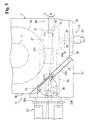
- Figs. 2 and 3 are a left-hand side view and a plan view, respectively, of a headstock on which the C-axis driving system is provided;
- Fig. 4 is a cross-sectional plan view of the C-axis driving system taken along the line IV - IV of Fig. 5;
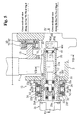
- Fig. 5 is a cross-sectional front view of the C-axis driving system taken along the line Va - Va and the line Vb - Vb of Fig. 4;
- FIG. 6 is a cross-sectional side view of the pivotal shaft part of the C-axis driving system taken along the line VI - VI of Fig. 5;
- Fig. 7 is a cross-sectional side view of the engagement part between the worm wheel and the worm taken along the line VII - VII of Fig. 5;
- Fig. 8 is a schematic perspective view of the C-axis driving system; and
- Fig. 9 is a perspective view of the worm shaft base.
- reference numeral 1 denotes a vertical NC lathe, which has the following structure, roughly. That is, a headstock 3 is fixedly mounted on a fixed bed 2, and a saddle 4 is provided upward of the headstock 3 of a column 2a so as to be movable in the X-axis direction (horizontal direction). Further, a tool post 5 is provided on the saddle 4 so as to be movable in the Z-axis direction (vertical direction), and a turret head 6 with turning tools, rotating tools or other cutting tools (not shown) loaded thereon is provided on the tool post 5 so that a required cutting tool can be rotationally indexed to a machining position.
- the headstock 3 is rectangular-parallelopiped box shaped, and a spindle 7 is inserted in the headstock 3 so as to be rotatable via bearings 8, 8.
- the spindle 7 is so positioned that its axis is directed vertical (along the Z-axis).
- a chuck 9 for gripping a workpiece W is mounted at an upper end portion of the spindle 7, while a hydraulic cylinder mechanism 10 for driving the opening/closing of a gripping claw 9a of the chuck 9 is connected to a lower end portion of the spindle 7.
- a spindle driving shaft 11 is inserted parallel to the spindle 7 so as to be rotatable via bearings 12, 12.
- the spindle driving shaft 11 is linked with a driving gear 13 fixedly mounted on the spindle 7 via an unshown power transmission member.
- a pulley 11a is mounted at a lower end of the spindle driving shaft 11, and an unshown spindle driving motor is linked with the pulley 11a via a belt.
- the headstock 3 is provided with a C-axis driving system 15.
- This C-axis driving system 15 is equipped with a worm wheel 16 mounted on the spindle 7 below the driving gear 13, a worm shaft 17 engageable with the worm wheel 16, and a C-axis unit 18 which drives the worm shaft 17 into rotation between an engagement position A where the worm shaft 17 engages with the worm wheel 16 and a disengagement position B where the worm shaft 17 is disengaged therefrom and withdrawn.
- the worm wheel 16 which is annular shaped, is mounted and fixedly bolted on an outer peripheral portion of a disc member 19 fixedly mounted on the spindle 7.
- the worm shaft 17 is positioned on the front side of the spindle 7 and perpendicular to the spindle axis (along the X axis), and a worm 17a is formed at an axially central portion of the worm shaft 17.
- the C-axis unit 18 is made up of a worm shaft base 20 for housing the worm shaft 17, a C-axis driving motor 21 for driving the worm shaft 17 into rotation, a C-axis base 22 for swingably supporting the worm shaft base 20, and a C-axis coupling hydraulic cylinder mechanism 23 for driving the worm shaft base 20 into rotation.
- an opening 3c is formed by cutting out the portion, and the C-axis base 22 is placed at this opening 3c.
- This C-axis base 22 is triangular shaped as seen in a plan view along the cut-out portion of the headstock 3, so that the headstock 3 is prevented from increasing in size due to the installation of the C-axis base 22.
- a flange 22a is formed at a peripheral portion of the C-axis base 22, and the flange 22a is fixedly tightened at an edge portion of the opening 3c with a bolt 24.
- a rectangular hole 22c In a left side wall 22b of the C-axis base 22, is formed a rectangular hole 22c having such a size as to allow the worm shaft base 20 to be passed therethrough.
- the worm shaft base 20 which is rectangular-cylindrical shaped with both ends opened, extends so as to be inserted through the rectangular hole 22c of the C-axis base 22 and the opening 3c of the headstock 3 and to confront the worm wheel 16.
- the worm shaft 17 is inserted into the worm shaft base 20, and supported so as to be rotatable via bearings 25, 25 mounted on both end portions of the worm shaft 17.
- a window 20b having such a size as to allow a front end portion of the worm wheel 16 to be inserted therein is formed as a cutout in a rear side wall 20a of the worm shaft base 20.
- An outer end portion of the worm shaft base 20 protrudes outward of the C-axis base 22, and a flange 20d is formed at an outer end edge of the protruding portion.
- the C-axis driving motor 21 is fixedly bolted to this flange 20d.
- a rotating shaft 21a of this C-axis driving motor 21 extends into the worm shaft base 20 so as to be coaxially opposed to the worm shaft 17, and this rotating shaft 21a and the worm shaft 17 are fixedly connected to each other in series with a coupling member 27 (see Fig. 5).
- an expandable/contractible seal cover 28 (see Fig. 4) is provided so as to cover between the flange 20d of the worm shaft base 20 and the C-axis base 22, thereby preventing invasion of dusts or the like from outside into the headstock 3.
- Pivotal shafts 30, 30 are provided on the worm shaft base 20 so as to be coaxial with each other. Each pivotal shaft 30 of these is so positioned that its pivotal axis is directed along the vertical direction (Z-axis direction), which is perpendicular to the axis of the worm shaft 17, and the pivotal shaft 30 is fixedly tightened with a plurality of bolts 31 to an upper wall 20e and a lower wall 20f of the worm shaft base 20 in proximity to the C-axis driving motor 21.
- each pivotal shaft 30 is inserted through an insertion hole 22g formed in a top wall 22e and a bottom wall 22f of the C-axis base 22 so as to protrude a little outward, and is rotatably supported by bearings 32, 32 fixedly mounted on an inner circumferential surface of the insertion hole 22g.
- the protruding portions of the pivotal shafts 30 are covered with caps 34, 34, respectively, the caps 34 being fixedly bolted to the C-axis base 22.
- the worm shaft base 20 is supported by the C-axis base 22 so as to be rotatable back and forth about the pivotal shaft 30.
- An opening 3e is formed as a cutout at a portion of the front wall 3a of the headstock 3 confronting an inner end portion of the worm shaft base 20, and the C-axis coupling hydraulic cylinder mechanism 23 is inserted in the opening 3e.
- This hydraulic cylinder mechanism 23, having a structure, roughly, that a piston rod 36 is advanceably and retreatably inserted in a cylinder 35, and the hydraulic cylinder mechanism 23 is fixedly installed on a plate 37 fixedly bolted to the front wall 3a so as to close the opening 3e.
- a rectangular-plate shaped coupling block 38 is fixedly bolted at the inner end portion of the worm shaft base 20.
- a recessed portion 38a having a U-shaped cross section is formed in the rear side wall, and a rectangular window 38b communicating with the recessed portion 38a is formed at a central portion of the front wall, where a fore end portion 36a of the piston rod 36 is inserted into the rectangular window 38b.
- a tapered stopper portion 38c which makes surface-contact with the rear end face of the plate 37 at the disengagement position B, so that the worm shaft base 20 is restricted to the disengagement position B by this stopper portion 38c (see Fig. 4).
- a columnar coupling pin 39 is inserted with its axis vertical. At an axially central portion of this coupling pin 39, is formed a cutout portion 39a, to which the fore end portion 36a of the piston rod 36 is fixedly screwed.
- This coupling pin 39 functions to absorb the rotational motion of the worm shaft base 20 due to the advance and retreat of the piston rod 36.
- a positioning guide block 40 which is fixedly bolted to the headstock 3.
- This positioning guide block 40 is L-shaped in a right-hand side view, having a rearwardly extending guide portion 40b integrally formed at the lower end of a vertically extending positioning portion 40a, where a guide groove 40c extending in the back-and-forth direction is formed in the left-hand side wall of the guide portion 40b.
- a guide portion 41 which slidably engages in the guide groove 40c is integrally formed at an inner end portion of the lower wall 20f of the worm shaft base 20.
- a positioning portion 42 confronting the front face of the positioning portion 40a is integrally formed at an inner end portion of a front wall 20h of the worm shaft base 20, and a contact block 43 is fixedly bolted to the positioning portion 42.
- This contact block 43 when making contact with the positioning portion 40a, positions the worm shaft base 20 to the engagement position A. As a result of this, the pressing force of the piston rod 36 of the hydraulic cylinder mechanism 23 is prevented from acting on the engagement portion of the worm 17a and the worm wheel 16.
- the spindle 7 is also equipped with a hydraulic clamp mechanism 50 for fixing the spindle 7 to a rotational index position, as shown in Figs. 4 and 5.
- This hydraulic clamp mechanism 50 has four pairs of pistons 51, 51 disposed circumferentially, each pair being opposed to each other with the driving gear 13 interposed therebetween.
- Each piston 51 is inserted in a common cylinder block 52, and driven to advance and retreat between a clamp position where the driving gear 13 is fixedly clamped by hydraulic pressure and an unclamp position where the driving gear 13 is unclamped. It is noted that in Fig. 5, the upper piston 51 shows an unclamped state while the lower piston 51 shows a clamped state.
- the worm shaft base 20 is withdrawn to the disengagement position B and the piston 51 of the hydraulic clamp mechanism 50 is withdrawn to the unclamp position.
- the spindle 7 is driven into rotation by the spindle driving motor, and the turning tool indexed to the machining position by the turret head 6 cuts into the workpiece W.
- the spindle 7 is stopped from rotating, then the piston rod 36 of the hydraulic cylinder mechanism 23 advances and the worm shaft base 20 is pivoted until the contact block 43 makes contact with the positioning guide block 40.
- the worm shaft base 20 is fixedly positioned to the engagement position A where the worm 17a engages with the worm wheel 16.
- the contact block 43 is in contact with the guide block 40, thereby blocking the worm shaft base 20 from pivoting toward engagement.
- the hydraulic pressure of the hydraulic cylinder mechanism 23 never acts on the worm wheel 16.
- the worm shaft base 20 is guided by the guide groove 40c of the guide block 40, the worm shaft base 20 is allowed to smoothly pivot without occurrence of up-and-down shifts.
- the C-axis driving motor 21 drives the worm shaft 17 into rotation so that the spindle 7 is rotationally indexed to a specified rotational angle.
- the pistons 51 of the hydraulic clamp mechanism 50 clamp the driving gear 13 to fix the spindle 7.
- the tool post 5 turns the turret head 6 to rotationally index a required rotating tool to a machining position, so that the workpiece W is subjected to rotating work such as milling or drilling with the rotating tool.
- the worm shaft 17 is placed and housed within the rectangular-cylindrical shaped worm shaft base 20, while the pivotal shaft 30 is placed on the upper wall 20e and the lower wall 20f of the worm shaft base 20 so as to be directed along the vertical direction, which is perpendicular to the axis of the worm shaft 17, and further the pivotal shaft 30 is rotatably supported by the C-axis base 22. Therefore, the worm shaft base 20 can be set to such a size that the worm shaft 17 can be housed therein, thus allowing the worm shaft base 20 to be smaller in size as compared with the conventional case where the worm shaft and the pivotal shaft are housed in a unit casing with a distance therebetween.
- the C-axis unit 18 as a whole to be downsized. Also, since the pivotal shaft 30 is placed perpendicular to the worm shaft 17, the axial length of the pivotal shaft 30 can be made shorter as compared with the conventional case where the pivotal shaft is set equal in length to the worm shaft. From this point as well, the C-axis unit 18 can be downsized.
- the worm shaft base 20 can be downsized, the structure can be simplified as compared with the conventional case where the large-size unit casing is provided. Resultantly, the parts count can be reduced and moreover the cost can be reduced.
- the rotational angle of the worm shaft base 20 can be made small by setting a large distance between the worm 17a and the pivotal shaft 30. As a result, a smooth engagement with the worm wheel 16 can be achieved.
- the C-axis driving motor 21 is connected in series at the outer end of the worm shaft base 20, and the hydraulic cylinder mechanism 23 is connected to the inner end portion of the worm shaft base 20.
- the pivotal operation force of the worm shaft base 20 can be made small, allowing the hydraulic cylinder mechanism 23 to be downsized as compared with the conventional case where the whole unit including the C-axis driving motor is pivoted. From this point as well, the whole unit can be decreased in size.
Landscapes
- Engineering & Computer Science (AREA)
- Mechanical Engineering (AREA)
- Turning (AREA)
- Machine Tool Positioning Apparatuses (AREA)
- Gear Transmission (AREA)
Abstract
Description
Claims (2)
- A C-axis driving system for machine tools including a worm wheel mounted on a spindle rotatably supported by a headstock, a worm shaft with a worm formed therein directed perpendicular to an axis of the spindle and provided so as to be pivotable about a pivotal shaft between an engagement position where the worm shaft is engaged with the worm wheel and a disengagement position where the worm shaft is disengaged therefrom, and a C-axis driving motor connected to the worm shaft and serving for rotationally indexing the spindle to a specified rotational angle, wherein the worm shaft is rotatably supported by a worm shaft base, the pivotal shaft is provided on the worm shaft base so as to be directed perpendicular to an axis of the worm shaft, and the pivotal shaft is supported by the headstock.
- The C-axis driving system according to Claim 1, wherein the C-axis driving motor is connected in series to an end portion of the worm shaft of the worm shaft base, and the pivotal shaft is placed at a proximity to the C-axis driving motor between the worm of the worm shaft and the C-axis driving motor.
Applications Claiming Priority (2)
| Application Number | Priority Date | Filing Date | Title |
|---|---|---|---|
| JP2000156815 | 2000-05-26 | ||
| JP2000156815A JP4643796B2 (en) | 2000-05-26 | 2000-05-26 | C-axis drive device for machine tools |
Publications (3)
| Publication Number | Publication Date |
|---|---|
| EP1157779A2 true EP1157779A2 (en) | 2001-11-28 |
| EP1157779A3 EP1157779A3 (en) | 2002-09-11 |
| EP1157779B1 EP1157779B1 (en) | 2004-07-28 |
Family
ID=18661545
Family Applications (1)
| Application Number | Title | Priority Date | Filing Date |
|---|---|---|---|
| EP01113031A Expired - Lifetime EP1157779B1 (en) | 2000-05-26 | 2001-05-28 | C-Axis driving system for machine tools |
Country Status (4)
| Country | Link |
|---|---|
| US (1) | US6626058B2 (en) |
| EP (1) | EP1157779B1 (en) |
| JP (1) | JP4643796B2 (en) |
| DE (1) | DE60104480T2 (en) |
Families Citing this family (8)
| Publication number | Priority date | Publication date | Assignee | Title |
|---|---|---|---|---|
| US20090293688A1 (en) * | 2008-05-30 | 2009-12-03 | Benedikt Nillies | Metal forming machine and method for spinning/flow forming |
| CN103567462A (en) * | 2012-07-20 | 2014-02-12 | 鸿准精密模具(昆山)有限公司 | Lathe |
| DE102013223380A1 (en) * | 2013-01-10 | 2014-07-10 | Ford Global Technologies, Llc | Electric power steering for vehicles |
| CN108136554B (en) * | 2015-09-30 | 2020-04-07 | 株式会社牧野铣床制作所 | Machining center |
| CN108290264B (en) * | 2015-10-20 | 2020-03-31 | 株式会社富士 | Machining system |
| ES2894891T3 (en) * | 2018-09-12 | 2022-02-16 | Fidia Spa | C axis unit for machine tool with motor spindle |
| WO2022256906A1 (en) * | 2021-06-11 | 2022-12-15 | Petrovic Miro | Drive mechanism and viscous material dispensing gun |
| CN113857587A (en) * | 2021-10-25 | 2021-12-31 | 湖南中大创远数控装备有限公司 | Numerical control spiral bevel gear lapping machine tool |
Family Cites Families (10)
| Publication number | Priority date | Publication date | Assignee | Title |
|---|---|---|---|---|
| GB2126314B (en) * | 1982-09-03 | 1985-09-04 | 600 Group P L C The | Rotating tool turret machine main spindle drive mechanism |
| JPS59175906A (en) * | 1983-03-25 | 1984-10-05 | Yoshikazu Sato | Numerical control lathe |
| DD241704A1 (en) * | 1985-10-17 | 1986-12-24 | Zahnschneidemaschinen Fabrik M | DOUBLE MECHANICAL DRIVE OF A WORKPIECE TASTER FOR A TRIM MACHINE |
| JP2566543B2 (en) * | 1987-01-30 | 1996-12-25 | ヤマザキマザツク株式会社 | C-axis drive mechanism |
| JPH01114257A (en) | 1987-10-28 | 1989-05-02 | Fujitsu Ltd | Separating type reader |
| JPH01114257U (en) * | 1988-01-25 | 1989-08-01 | ||
| JPH01164049U (en) * | 1988-05-11 | 1989-11-15 | ||
| JPH02139050U (en) * | 1989-04-19 | 1990-11-20 | ||
| JPH0796441A (en) * | 1993-09-24 | 1995-04-11 | Eisuke Yokoyama | Backlash removal structure in worm / worm wheel mechanism |
| JP3284715B2 (en) * | 1993-12-15 | 2002-05-20 | 村田機械株式会社 | Indexing device for punch tools |
-
2000
- 2000-05-26 JP JP2000156815A patent/JP4643796B2/en not_active Expired - Fee Related
-
2001
- 2001-05-28 DE DE60104480T patent/DE60104480T2/en not_active Expired - Lifetime
- 2001-05-28 EP EP01113031A patent/EP1157779B1/en not_active Expired - Lifetime
- 2001-05-29 US US09/866,561 patent/US6626058B2/en not_active Expired - Lifetime
Also Published As
| Publication number | Publication date |
|---|---|
| JP2001334443A (en) | 2001-12-04 |
| EP1157779B1 (en) | 2004-07-28 |
| US6626058B2 (en) | 2003-09-30 |
| EP1157779A3 (en) | 2002-09-11 |
| JP4643796B2 (en) | 2011-03-02 |
| DE60104480T2 (en) | 2004-11-25 |
| DE60104480D1 (en) | 2004-09-02 |
| US20020017888A1 (en) | 2002-02-14 |
Similar Documents
| Publication | Publication Date | Title |
|---|---|---|
| US9333608B2 (en) | Machine tool and tool holder | |
| EP0887134B1 (en) | Tool spindle fixing device for composite machine tool | |
| US4087890A (en) | Compound lathe | |
| JP6480744B2 (en) | Machine Tools | |
| EP1897640B1 (en) | Machine tool | |
| JPS62236602A (en) | Machine tool | |
| KR101612129B1 (en) | attachment of the machine tool | |
| GB2307431A (en) | Turret machine tool | |
| EP1157779B1 (en) | C-Axis driving system for machine tools | |
| EP2711125B1 (en) | Safety device for rotating feed rod | |
| US6615466B1 (en) | Tool head with spindle bearing arrangement | |
| JP2535155B2 (en) | Vertical machining center with swivel pallet engineer | |
| JPH11254211A (en) | Turret turret equipment | |
| US20080066591A1 (en) | Machine tool | |
| WO2024106141A1 (en) | Machine tool | |
| JP3964642B2 (en) | Machine Tools | |
| EP0841121B1 (en) | Rotating-tool fixing structure in a tool turret | |
| TW202344325A (en) | Spindle devices, working machines equipped with spindle devices, and balancing testing machines | |
| JPH0120033B2 (en) | ||
| JP2557002Y2 (en) | Tool post of compound NC lathe | |
| JP2878996B2 (en) | Angular attachment for machine tools | |
| JP2000000739A (en) | Clamp detection device of turret clamp device | |
| JP2003181705A (en) | Rotating tool turret and two-spindle opposed lathe provided with the same | |
| KR200249682Y1 (en) | a device for opening and closing a magazine door of an umbrella type ATC | |
| JP2954879B2 (en) | Machine Tools |
Legal Events
| Date | Code | Title | Description |
|---|---|---|---|
| PUAI | Public reference made under article 153(3) epc to a published international application that has entered the european phase |
Free format text: ORIGINAL CODE: 0009012 |
|
| AK | Designated contracting states |
Kind code of ref document: A2 Designated state(s): AT BE CH CY DE DK ES FI FR GB GR IE IT LI LU MC NL PT SE TR |
|
| AX | Request for extension of the european patent |
Free format text: AL;LT;LV;MK;RO;SI |
|
| PUAL | Search report despatched |
Free format text: ORIGINAL CODE: 0009013 |
|
| AK | Designated contracting states |
Kind code of ref document: A3 Designated state(s): AT BE CH CY DE DK ES FI FR GB GR IE IT LI LU MC NL PT SE TR |
|
| AX | Request for extension of the european patent |
Free format text: AL;LT;LV;MK;RO;SI |
|
| 17P | Request for examination filed |
Effective date: 20030307 |
|
| AKX | Designation fees paid |
Designated state(s): DE FR GB IT |
|
| GRAP | Despatch of communication of intention to grant a patent |
Free format text: ORIGINAL CODE: EPIDOSNIGR1 |
|
| RIN1 | Information on inventor provided before grant (corrected) |
Inventor name: UEMURA, YOSHITANE Inventor name: UEDA, TOSHIO Inventor name: SASABE, NOBUAKI |
|
| GRAS | Grant fee paid |
Free format text: ORIGINAL CODE: EPIDOSNIGR3 |
|
| GRAA | (expected) grant |
Free format text: ORIGINAL CODE: 0009210 |
|
| AK | Designated contracting states |
Kind code of ref document: B1 Designated state(s): DE FR GB IT |
|
| PG25 | Lapsed in a contracting state [announced via postgrant information from national office to epo] |
Ref country code: FR Free format text: LAPSE BECAUSE OF FAILURE TO SUBMIT A TRANSLATION OF THE DESCRIPTION OR TO PAY THE FEE WITHIN THE PRESCRIBED TIME-LIMIT Effective date: 20040728 Ref country code: IT Free format text: LAPSE BECAUSE OF FAILURE TO SUBMIT A TRANSLATION OF THE DESCRIPTION OR TO PAY THE FEE WITHIN THE PRE;WARNING: LAPSES OF ITALIAN PATENTS WITH EFFECTIVE DATE BEFORE 2007 MAY HAVE OCCURRED AT ANY TIME BEFORE 2007. THE CORRECT EFFECTIVE DATE MAY BE DIFFERENT FROM THE ONE RECORDED.SCRIBED TIME-LIMIT Effective date: 20040728 |
|
| REG | Reference to a national code |
Ref country code: GB Ref legal event code: FG4D |
|
| REG | Reference to a national code |
Ref country code: IE Ref legal event code: FG4D |
|
| REF | Corresponds to: |
Ref document number: 60104480 Country of ref document: DE Date of ref document: 20040902 Kind code of ref document: P |
|
| PG25 | Lapsed in a contracting state [announced via postgrant information from national office to epo] |
Ref country code: GB Free format text: LAPSE BECAUSE OF NON-PAYMENT OF DUE FEES Effective date: 20050528 |
|
| PLBE | No opposition filed within time limit |
Free format text: ORIGINAL CODE: 0009261 |
|
| STAA | Information on the status of an ep patent application or granted ep patent |
Free format text: STATUS: NO OPPOSITION FILED WITHIN TIME LIMIT |
|
| 26N | No opposition filed |
Effective date: 20050429 |
|
| EN | Fr: translation not filed | ||
| GBPC | Gb: european patent ceased through non-payment of renewal fee |
Effective date: 20050528 |
|
| PGFP | Annual fee paid to national office [announced via postgrant information from national office to epo] |
Ref country code: DE Payment date: 20170724 Year of fee payment: 17 |
|
| REG | Reference to a national code |
Ref country code: DE Ref legal event code: R119 Ref document number: 60104480 Country of ref document: DE |
|
| PG25 | Lapsed in a contracting state [announced via postgrant information from national office to epo] |
Ref country code: DE Free format text: LAPSE BECAUSE OF NON-PAYMENT OF DUE FEES Effective date: 20181201 |