EP1156555A2 - Verbinder - Google Patents
Verbinder Download PDFInfo
- Publication number
- EP1156555A2 EP1156555A2 EP01111714A EP01111714A EP1156555A2 EP 1156555 A2 EP1156555 A2 EP 1156555A2 EP 01111714 A EP01111714 A EP 01111714A EP 01111714 A EP01111714 A EP 01111714A EP 1156555 A2 EP1156555 A2 EP 1156555A2
- Authority
- EP
- European Patent Office
- Prior art keywords
- locking
- connector according
- connecting element
- electrical line
- electrical
- Prior art date
- Legal status (The legal status is an assumption and is not a legal conclusion. Google has not performed a legal analysis and makes no representation as to the accuracy of the status listed.)
- Withdrawn
Links
Images



Classifications
-
- H—ELECTRICITY
- H01—ELECTRIC ELEMENTS
- H01R—ELECTRICALLY-CONDUCTIVE CONNECTIONS; STRUCTURAL ASSOCIATIONS OF A PLURALITY OF MUTUALLY-INSULATED ELECTRICAL CONNECTING ELEMENTS; COUPLING DEVICES; CURRENT COLLECTORS
- H01R13/00—Details of coupling devices of the kinds covered by groups H01R12/70 or H01R24/00 - H01R33/00
- H01R13/62—Means for facilitating engagement or disengagement of coupling parts or for holding them in engagement
- H01R13/629—Additional means for facilitating engagement or disengagement of coupling parts, e.g. aligning or guiding means, levers, gas pressure electrical locking indicators, manufacturing tolerances
- H01R13/62905—Additional means for facilitating engagement or disengagement of coupling parts, e.g. aligning or guiding means, levers, gas pressure electrical locking indicators, manufacturing tolerances comprising a camming member
-
- H—ELECTRICITY
- H01—ELECTRIC ELEMENTS
- H01R—ELECTRICALLY-CONDUCTIVE CONNECTIONS; STRUCTURAL ASSOCIATIONS OF A PLURALITY OF MUTUALLY-INSULATED ELECTRICAL CONNECTING ELEMENTS; COUPLING DEVICES; CURRENT COLLECTORS
- H01R13/00—Details of coupling devices of the kinds covered by groups H01R12/70 or H01R24/00 - H01R33/00
- H01R13/40—Securing contact members in or to a base or case; Insulating of contact members
- H01R13/42—Securing in a demountable manner
- H01R13/436—Securing a plurality of contact members by one locking piece or operation
- H01R13/4361—Insertion of locking piece perpendicular to direction of contact insertion
Definitions
- the invention relates to a connector, in particular in motor vehicles used electrical cables.
- Such connectors are used, for example, in motor vehicles to electrical Contact lines with various electrical devices.
- the invention creates a possibility, one on a connecting element fixed electrical cable additionally by means of a locking element to lock on the connecting element.
- the electrical line is also against loosening from the connecting element secured.
- the locking element is as a separate component is provided.
- the is fixed first locked electrical line on the connecting element and by means of Locking element on the connecting element second lockable.
- Locking element on the connecting element With the locking element is consequently created a second locking, which allows the electrical first locked on the connecting element Line through an additional lock on the connecting element to back up. This makes a particularly safe and reliable coupling achieved the electrical line with the connecting element.
- the electrical line is designed as a multiple conductor, the multiple conductor connected to a common strip-shaped carrier having.
- Connector thus for coupling to a multiple conductor, in particular an FPC, designed with the possibility of the locking element is created, such a multiple leader or an FPC on Lock connecting element.
- a separate holding element is provided, which with the connecting element can be coupled, in particular latched.
- the holding element is designed as a strain relief member.
- the holding element is advantageously used on the electrical Absorbing tensile forces acting on the line. This prevents that a located in a target position relative to the connecting element Contact area or contact section of the electrical line through such tensile forces unintentionally moved out of the target position becomes.
- the locking element for the second locking of the electrical line with the holding element designed for the first locking of the electrical line connectable.
- the electrical line is via the holding element first locked and via the interacting with the holding element Locking element second locked.
- the coupling of the locking element with the connecting element is preferably done in that the locking element is approximately vertical can be pushed onto the connecting element to the longitudinal axis of the electrical line is. It is preferably provided that the locking element at least in a locking position and preferably also when pushed onto the connecting element parallel to the longitudinal axis the electrical line is immobile.
- a preferred development of the invention proposes the locking element approximately U-shaped, preferably flat U-legs are provided, which are parallel in a locking position lie to the electrical line.
- the locking action of the locking element is preferred Embodiment of the invention achieved in that the locking element has at least one preferably groove-like recess, in the at least in a locking position and preferably also when sliding the locking element onto the connecting element at least one provided for the first locking of the electrical line Projection engages.
- the recess is preferably on the inside of a U-leg of the locking element.
- the one engaging in the recess Projection is preferably on one with the connecting element couplable holding element provided.
- the connecting element on two approximately parallel walls, the mutually facing insides a receptacle for a holding element Limit the first locking of the two electrical lines and their Outside each as a contact surface for one of the electrical lines are trained.
- the electrical Line formed as a single conductor preferably in the form of a wire is provided, which is preferably with insulation and an in the connecting element is provided with a pluggable contact element.
- the connecting element preferably has at least one chamber on, into which a contact element of the electrical line can be plugged and in which the contact element can be locked first.
- the connecting element preferably has a plurality of in particular arranged in pairs Chambers on.
- the electrical line it is preferably provided on the connecting element that the locking element approximately perpendicular to the longitudinal axis of the electrical line can be inserted into the connecting element.
- the locking element preferably has several in particular pin-shaped locking sections, each in at least a chamber of the connecting element can be inserted.
- the locking element is designed like a comb.
- a particularly secure locking is achieved in that according to a another embodiment of the invention, the locking element can be inserted via a side wall of the connecting element and in a locking position with the opposite side wall in Intervention stands.
- the locking element in is locked in a locking position with the connecting element. On unintentional loosening of the lock is thereby reliably prevented.
- the connector according to the invention is preferably part of a connection module for different types of electrical lines, at least two separate connecting elements, one of which with at least a multiple conductor and the other with at least one single conductor can be coupled, and has a common housing, in that the connecting elements can be inserted and that for simultaneous Contacting the multiple conductor and the single conductor with an electrical Device is trained.
- connection module comprises at least two differently trained embodiments of the connector according to the invention different types of electrical lines, in particular at least one Multiple leaders, e.g. in the form of an FPC, and at least one single conductor, to be contacted simultaneously with an electrical device.
- connection module of this type is the subject of the same day as the present application filed German patent application the applicant (attorney's file number: D 3609).
- FIGS Subclaims Further preferred embodiments of the invention are also shown in FIGS Subclaims, the description and the drawing.
- connection module is given with reference to FIGS. 1-4 given, whereupon with reference to FIGS. 5 - 10 in more detail on its individual Components is received.
- FPC Flexible Printed Circuit
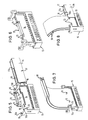
- the FPCs 10 are first locked on the connecting element 15 and by means of of a laterally slidable locking element 17 second locked. This will be discussed in more detail elsewhere in connection with FIGS. 5-8.
- the connection module comprises a further connection element 65 for a plurality of electrical lines 60, each in the form of a single conductor are provided.
- the individual conductors 60 are insulated Wires, each provided with a contact element, not shown are with which they are inserted into chambers of the connecting element 65 and are locked into it first.
- the individual conductors 60 and / or their Contact elements can be designed differently.
- the locking element 67 becomes perpendicular to the longitudinal extent of the individual conductors 60 in the connecting element 65 inserted. This will be communicated elsewhere with Fig. 10 in more detail.
- connection module further comprises a cuboid-shaped receiving housing 20 with two chambers for the connecting elements 16, 65, the via receiving openings 21, 22 on the same side of the receiving housing 20 are accessible.
- the receiving housing 20 can be coupled to a head piece 50.
- the Headpiece 50 is provided with a contact arrangement 54, of which only downward projecting pins are shown.
- the compound State of the connection module exist between the electrical Lines 10, 60 and the contact arrangement 54 electrical connections.
- a U-shaped actuator 40 For coupling the receiving housing 20 to the head piece 50 is a U-shaped actuator 40 provided that with its U-legs 42, 43 via openings 25 in an end face of the receiving housing 20 in this is insertable.
- the U-legs 42, 43 are together connecting U-web of the actuator 40 as an actuating section 44 trained.
- the legs 42, 43 are each on the outside with two inclined Provided longitudinal recesses, the control surfaces 41 for at the Inner walls of the head piece 50 formed, peg-shaped control projections 51 form.
- the actuator 40 When the actuator 40 is inserted the control projections 51 on the control surfaces 41 positively guided, so that the actuator 40 is positively guided on the head piece 50.
- the actuator 40 By pushing the actuator 40 into the receiving housing 20 the head piece 50 is pulled onto the receiving housing 20, to in this way the contact arrangement 54 with the electrical To contact lines 10, 60 with their contact areas or Contact elements are arranged in the connecting elements 15, 65.
- Fig. 2 shows the connection module with inserted in the receiving housing 20 Connecting elements 15, 65 and with up to a starting position in the receiving housing 20 inserted actuator 40.
- a U-shaped securing member 30 is provided, which with its profiled U legs 31, 32 via four holding sections 23 of the receiving housing 20 and four holding sections 16, 66 of the connecting elements 15, 65 is pushed. This will be discussed in more detail elsewhere.
- Fig. 3 shows the secured state in which the securing member 30 the receiving housing 20 is pushed on.
- the electrical lines 10, 60 run between the legs 31, 32 of the securing element 30 through which the receiving openings 21, 22 of the receiving housing 20 partially cover the connecting elements 15, 65.
- the security organ 30 over one at its Leg 31, 32 connecting web 34 formed locking portion the receiving housing 20 locked. This is also discussed elsewhere discussed in more detail.
- the actuator 40 is behind as before in the starting position according to FIG. 2.
- the receiving housing 20 placed on the head piece 50, so that by inserting the Actuator 40 and interaction of the control projections 51st and the control surfaces 41 on the legs 42, 43 of the actuator 40 the final assembled state according to FIG. 4 are produced can.
- the connecting elements 15, 65 are through Securing member 30 secured in the receiving housing 20 against being pulled out.
- the actuator 40 ensures a secure connection between the receiving housing 20 and the contact piece 50. This ensures reliable contact between the electrical lines 10, 60 and the contact arrangement 54 guaranteed.
- the connecting elements 15, 65, the receiving housing 20 and the head piece 50 are each formed symmetrically such that the security element 30 and the actuator 40 from both sides can be pushed on or pushed in.
- connection module - Can be plugged into an electrical device 55 which in Fig. 4 is indicated only schematically by a dashed line.
- connection module is used in a motor vehicle in connection with a central electrical unit, also called "Bus Electrical Center”(BEC).
- BEC Bus Electrical Center
- the FPC connecting element 15 has a receptacle 19 for a holding element 70 serving as a strain relief member.
- the holding element 70 comprises a long U-web 72, from the free ends of each a short U-leg designed as locking arm 71 protrudes vertically. With the elastically deflectable locking arms 71 is the holding element 70 lockable on the connecting element 15.
- the holding element 70 fulfills a strain relief function, by absorbing tensile forces acting on the FPCs 10 and prevents the FPCs 10 from accidentally touching their contact areas can be pulled out of the connecting element 15.
- the first locked in the state according to FIG. 7 on the connecting element 15 FPCs 10 are on the connecting element by means of the locking element 17 15 second locked.
- the locking element 17 is U-shaped Slider formed, the U-legs 17a, 17b between below holding sections 16 and a base section 13 of the connecting element 15 can be pushed.
- there is an upper edge of each of the legs 17a, 17b Slits 16a of the holding portions 16 are engaged while one The lower edge of the legs 17a, 17b slides along the base section 13.
- FIG. 5 shows in particular on the inner sides of the legs 17a, 17b of the locking element 17 formed longitudinal recesses 18 with which the locking element 17 when pushed onto the connecting element 15 on the projections 73 on the connecting element 15 latched holding element 70 is positively guided.
- the holding sections 16 of the connecting element 15 each have one curved retaining lug 16b.
- the holding lugs 16b are shaped in such a way that they are arranged in the receiving housing 20 connecting element 15 congruently in areas with the holding sections 23 of the receiving housing 20 are arranged (see FIG. 2).
- FIG. 9 shows the receiving housing 20 with connecting elements arranged therein 15, 65 and with the securing member 30 pushed on, in addition, which is pushed onto the locking element 15, the Longitudinal recesses 18 having locking element 17 is shown.
- the holding sections 23 of the receiving housing 20 are complementary to the approximately C-shaped profile of the legs 31, 32 of the securing element 30 educated. Holding lugs 23a, 23b of the holding sections 23 are thereby of webs 35, 36 of the legs 31, 32 engaging behind.
- the holding noses 23a are congruent with those not shown in FIG. 9 Holding lugs 16b of the holding sections 16 of the connecting element 15 and with holding lugs 66a of the holding sections 66 of the connecting element 65 (see Fig. 10) arranged.
- the connecting elements 15, 65 are in relation to their direction of insertion fixed in the receiving housing 20 by the securing member 30. In particular, the connecting elements 15, 65 cannot be accidentally are pressed too far into the receiving housing 20.
- the holding lugs 23a of the holding portions 23 of the receiving housing 20 the securing member 30 in the direction of insertion of the connecting elements 15, 65 fix, the holding lugs 23b prevent them from being pushed apart the legs 31, 32 of the safety device 30.
- Fig. 9 are also those formed on the opposite side Openings 25 of the receiving housing 20 for the legs 42, 43 of the actuator 40 and the slot-shaped recesses 24 for the control projections 51 of the head piece 50 are shown (see FIGS. 1-4).
- FIG. 10 shows the essentially cuboid connecting element 65 for the individual conductors 60, which has a plurality of chambers 61 into which the Individual conductors 60 with their contact elements, not shown, can be inserted are.
- the chambers 61 and the contact elements of the individual conductors 60 are designed such that the contact elements - and thus the individual conductors 60 - by plugging into the chambers 61 on the connecting element 65 are locked first.
- the locking element 67 has an elongated connecting section 69, of which several locking pins 68 like the prongs of one Stand vertically.
- the locking pins 68 Via openings 62 in a side wall of the connecting element 65 are the locking pins 68 each by two arranged one behind the other Chambers 61 insertable. When fully inserted of the locking element 67 are the free end sections the locking pins 68 with openings on the opposite Side of the connecting element 65 in engagement (see. Fig. 1).
- the locking element 67 is in the locking position via a detent formed on an outer locking pin 68 63 with a corresponding opening 64a, elastic deflectable tab 64 of the connecting element 65 locked.
- the locking pins 68 of the locking element 67 before appropriately trained locking areas the contact elements of the single conductor 60 pushed so that the individual conductors 60 against pulling out of the chambers 61 of the connecting element 65 are secured.
- the locking element 67 a second lock for the first locked on the connecting element 65 Single conductor 60 created.
- the holding sections 66 of the connecting element each having a holding lug 66a 65 are identical to the holding sections 16 of the Connecting element 15 executed.
- the retaining tabs 66a are also thus when the securing member 30 is pushed on (see FIG. 9) from the on whose legs 31, 32 engage behind formed locking webs 35.
Landscapes
- Details Of Connecting Devices For Male And Female Coupling (AREA)
Abstract
Description
- Fig. 1 - 4
- eine Ausführungsform des zwei erfindungsgemäße Verbinder umfassenden Verbindungsmoduls gemäß der Erfindung in verschiedenen Stadien des Zusammensetzens,
- Fig. 5 - 8
- den FPC-Verbinder für flexible gedruckte Schaltungen des Verbindungsmoduls in verschiedenen Stadien des Zusammensetzens,
- Fig. 9
- das Verbindungsmodul im teilweise zusammengesetzten Zustand ohne elektrische Leitungen, und
- Fig. 10
- den Einzelleiter-Verbinder des Verbindungsmoduls.
- 10
- Leitung, Mehrfachleiter, FPC
- 11
- Träger
- 12
- Leiter
- 13
- Basisabschnitt
- 14
- Anlagefläche
- 15
- Verbindungselement
- 16
- Halteabschnitt
- 16a
- Schlitz
- 16b
- Haltenase
- 17
- Verriegelungselement
- 17a
- U-Schenkel
- 17b
- U-Schenkel
- 18
- Aussparung, Vertiefung
- 19
- Aufnahme
- 20
- Aufnahmegehäuse
- 21
- Aufnahmeöffnung
- 22
- Aufnahmeöffnung
- 23
- Halteabschnitt
- 23a
- Haltenase
- 23b
- Haltenase
- 24
- Aussparung
- 25
- Öffnung
- 30
- Sicherungsorgan
- 31
- U-Schenkel
- 32
- U-Schenkel
- 33
- Rastabschnitt
- 34
- Steg
- 35
- Steg
- 36
- Steg
- 40
- Betätigungsorgan
- 41
- Steuerfläche
- 42
- U-Schenkel
- 43
- U-Schenkel
- 44
- Betätigungsabschnitt
- 45
- Endbereich
- 46
- Einführbereich
- 50
- Kopfstück
- 51
- Steuervorsprung
- 54
- Kontaktanordnung
- 55
- elektrische Einrichtung
- 60
- Leitung, Einzelleiter, Draht
- 61
- Kammer
- 62
- Durchbruch
- 63
- Rastnase
- 64
- Lasche
- 64a
- Öffnung
- 65
- Verbindungselement
- 66
- Halteabschnitt
- 66a
- Haltenase
- 67
- Verriegelungselement
- 68
- Verriegelungsabschnitt, Verriegelungsstift
- 69
- Verbindungsabschnitt
- 70
- Halteelement, Zugentlastungsorgan
- 71
- U-Schenkel, Rastarm
- 72
- U-Steg
- 73
- Vorsprung
Claims (24)
- Verbinder für insbesondere in Kraftfahrzeugen verwendete elektrische Leitungen (10, 60) mit zumindest einem Verbindungselement (15, 65), an dem wenigstens eine elektrische Leitung (10, 60) fixierbar ist, und mit zumindest einem Verriegelungselement (17, 67), mit dem die fixierte elektrische Leitung (10, 60) am Verbindungselement (15, 65) verriegelbar ist.
- Verbinder nach Anspruch 1,
dadurch gekennzeichnet, daß die fixierte elektrische Leitung (10, 60) am Verbindungselement (15, 65) erstverriegelt und mittels des Verriegelungselementes (17, 67) am Verbindungselement (15, 65) zweitverriegelbar ist. - Verbinder nach Anspruch 1 oder 2,
dadurch gekennzeichnet, daß die elektrische Leitung (10) als Mehrfachleiter ausgebildet ist, der mehrere mit einem gemeinsamen streifenförmigen Träger (11) verbundene Leiter (12) aufweist und vorzugsweise in Form einer flexiblen gedruckten Schaltung (FPC) vorgesehen ist. - Verbinder nach einem der vorhergehenden Ansprüche,
dadurch gekennzeichnet, daß zur Erstverriegelung der elektrischen Leitung (10) am Verbindungselement (15) ein separates Halteelement (70) vorgesehen ist, das mit dem Verbindungselement (15) koppelbar, insbesondere verrastbar ist. - Verbinder nach Anspruch 4,
dadurch gekennzeichnet, daß das Halteelement (70) als Zugentlastungsorgan ausgebildet ist. - Verbinder nach Anspruch 4 oder 5,
dadurch gekennzeichnet, daß das Verriegelungselement (17) zur Zweitverriegelung der elektrischen Leitung (10) mit dem zur Erstverriegelung der elektrischen Leitung (10) ausgebildeten Halteelement (70) koppelbar ist. - Verbinder nach einem der Ansprüche 4 bis 6,
dadurch gekennzeichnet, daß das Halteelement (70) mittels des Verriegelungselementes (17) am Verbindungselement (15) verriegelbar ist. - Verbinder nach einem der vorhergehenden Ansprüche,
dadurch gekennzeichnet, daß das Verriegelungselement (17) etwa senkrecht zur Längsachse der elektrischen Leitung (10) auf das Verbindungselement (15) aufschiebbar ist. - Verbinder nach einem der vorhergehenden Ansprüche,
dadurch gekennzeichnet, daß das Verriegelungselement (17) zumindest in einer Verriegelungsstellung und bevorzugt außerdem beim Aufschieben auf das Verbindungselement (15) parallel zur Längsachse der elektrischen Leitung (10) unbeweglich ist. - Verbinder nach einem der vorhergehenden Ansprüche,
dadurch gekennzeichnet, daß das Verriegelungselement (17) etwa U-förmig ausgebildet ist und bevorzugt flache U-Schenkel (17a, 17b) aufweist, die in einer Verriegelungsstellung parallel zur elektrischen Leitung (10) liegen. - Verbinder nach einem der vorhergehenden Ansprüche,
dadurch gekennzeichnet, daß ein Halteelement (70) zur Erstverriegelung der elektrischen Leitung (10) wenigstens einen Vorsprung (73) aufweist, auf den die elektrische Leitung (10) aufsteckbar ist. - Verbinder nach Anspruch 11,
dadurch gekennzeichnet, daß der Vorsprung (73) über eine Anlagefläche (14) des Verbindungselementes (15) für die elektrische Leitung (10) vorsteht. - Verbinder nach einem der vorhergehenden Ansprüche,
dadurch gekennzeichnet, daß das Verriegelungselement (17) wenigstens eine bevorzugt nutartige Aussparung (18) insbesondere an der Innenseite eines U-Schenkels (17a, 17b) aufweist, in die zumindest in einer Verriegelungsstellung und bevorzugt außerdem beim Aufschieben des Verriegelungselementes (17) auf das Verbindungselement (15) wenigstens ein zur Erstverriegelung der elektrischen Leitung (10) vorgesehener Vorsprung (73) eingreift. - Verbinder nach einem der vorhergehenden Ansprüche,
dadurch gekennzeichnet, daß das Verbindungselement (15) zwei etwa parallele Wände aufweist, deren einander zugewandte Innenseiten eine Aufnahme (19) für ein Halteelement (70) zur Erstverriegelung zweier elektrischer Leitungen (10) begrenzen und deren Außenseiten jeweils als Anlagefläche (14) für eine der elektrischen Leitungen (10) ausgebildet sind. - Verbinder nach einem der vorhergehenden Ansprüche,
dadurch gekennzeichnet, daß ein Halteelement (70) etwa U-förmig ausgebildet ist, wobei die bevorzugt relativ kurzen U-Schenkel (71) in Form von Rastarmen vorgesehen sind und der bevorzugt relativ lange U-Steg (72) wenigstens einen seitlich abstehenden Vorsprung (73) zur Erstverriegelung der elektrischen Leitung (10) aufweist. - Verbinder nach Anspruch 1 oder 2,
dadurch gekennzeichnet, daß die elektrische Leitung (60) als Einzelleiter ausgebildet ist, der bevorzugt in Form eine Drahtes vorgesehen ist, welcher vorzugsweise mit einer Isolierung und einem in das Verbindungselement (65) steckbaren Kontaktelement versehen ist. - Verbinder nach Anspruch 16,
dadurch gekennzeichnet, daß das Verbindungselement (65) wenigstens eine Kammer (61) aufweist, in die ein Kontaktelement der elektrischen Leitung (60) steckbar und in der das Kontaktelement erstverriegelbar ist. - Verbinder nach Anspruch 16 oder 17,
dadurch gekennzeichnet, daß das Verbindungselement (65) eine Mehrzahl von bevorzugt paarweise angeordneten Kammern (61) aufweist. - Verbinder nach einem der Ansprüche 16 bis 18,
dadurch gekennzeichnet, daß das Verriegelungselement (67) zur Verriegelung der elektrischen Leitung (60) etwa senkrecht zur Längsachse der elektrischen Leitung (60) in das Verbindungselement (65) einsteckbar ist. - Verbinder nach einem der Ansprüche 16 bis 19,
dadurch gekennzeichnet, daß das Verriegelungselement (67) mehrere bevorzugt stiftförmige Verriegelungsabschnitte (60) aufweist, die jeweils in zumindest eine Kammer (61) des Verbindungselementes (65) einsteckbar sind. - Verbinder nach einem der Ansprüche 16 bis 20,
dadurch gekennzeichnet, daß das Verriegelungselement (67) kammartig ausgebildet ist. - Verbinder nach einem der Ansprüche 16 bis 21,
dadurch gekennzeichnet, daß das Verriegelungselement (67) über eine Seitenwand des Verbindungselementes (65) einsteckbar ist und in einer Verriegelungsstellung mit der gegenüberliegenden Seitenwand in Eingriff steht. - Verbinder nach einem der Ansprüche 16 bis 22,
dadurch gekennzeichnet, daß das Verriegelungselement (67) in einer Verriegelungsstellung mit dem Verbindungselement (65) verrastet ist. - Verbinder nach einem der vorhergehenden Ansprüche,
dadurch gekennzeichnet, daß er Bestandteil eines Verbindungsmoduls für verschiedenartige elektrische Leitungen (10, 60) ist, das wenigstens zwei separate Verbindungselemente (15, 65), von denen das eine mit wenigstens einem Mehrfachleiter (10) und das andere mit zumindest einem Einzelleiter (60) koppelbar ist, und ein gemeinsames Aufnahmegehäuse (20) aufweist, in das die Verbindungselemente (15, 65) einführbar sind und das zur gleichzeitigen Kontaktierung des Mehrfachleiters (10) und des Einzelleiters (60) mit einer elektrischen Einrichtung (55) ausgebildet ist.
Applications Claiming Priority (2)
| Application Number | Priority Date | Filing Date | Title |
|---|---|---|---|
| DE10024781 | 2000-05-19 | ||
| DE2000124781 DE10024781A1 (de) | 2000-05-19 | 2000-05-19 | Verbinder |
Publications (2)
| Publication Number | Publication Date |
|---|---|
| EP1156555A2 true EP1156555A2 (de) | 2001-11-21 |
| EP1156555A3 EP1156555A3 (de) | 2003-03-05 |
Family
ID=7642775
Family Applications (1)
| Application Number | Title | Priority Date | Filing Date |
|---|---|---|---|
| EP01111714A Withdrawn EP1156555A3 (de) | 2000-05-19 | 2001-05-14 | Verbinder |
Country Status (2)
| Country | Link |
|---|---|
| EP (1) | EP1156555A3 (de) |
| DE (1) | DE10024781A1 (de) |
Families Citing this family (3)
| Publication number | Priority date | Publication date | Assignee | Title |
|---|---|---|---|---|
| DE20206670U1 (de) | 2002-04-26 | 2002-12-19 | Leopold Kostal GmbH & Co. KG, 58507 Lüdenscheid | Elektrisches Steckverbindungsteil |
| DE10348915A1 (de) * | 2003-10-21 | 2005-05-25 | Bayerische Motoren Werke Ag | Steckverbindung für elektrische Leitungen in einem Fahrzeug |
| EP2933577B1 (de) | 2014-04-14 | 2017-12-06 | Mahle Behr France Rouffach S.A.S | Elektrische Heizvorrichtung |
Family Cites Families (6)
| Publication number | Priority date | Publication date | Assignee | Title |
|---|---|---|---|---|
| US4986764A (en) * | 1989-10-31 | 1991-01-22 | Amp Incorporated | High voltage lead assembly and connector |
| JP2547381Y2 (ja) * | 1992-07-28 | 1997-09-10 | 矢崎総業株式会社 | 多極コネクタ |
| US5443403A (en) * | 1993-03-10 | 1995-08-22 | The Whitaker Corporation | Composite electrical connector assembly with snap-in housing |
| US5266048A (en) * | 1993-03-26 | 1993-11-30 | The Whitaker Corporation | Gull-wing strain relief |
| TW346263U (en) * | 1997-08-16 | 1998-11-21 | Hon Hai Prec Ind Co Ltd | Connector of parallel wires |
| US5924891A (en) * | 1997-12-15 | 1999-07-20 | The Whitaker Corporation | Connector assembly for flat circuitry |
-
2000
- 2000-05-19 DE DE2000124781 patent/DE10024781A1/de not_active Withdrawn
-
2001
- 2001-05-14 EP EP01111714A patent/EP1156555A3/de not_active Withdrawn
Also Published As
| Publication number | Publication date |
|---|---|
| EP1156555A3 (de) | 2003-03-05 |
| DE10024781A1 (de) | 2001-11-22 |
Similar Documents
| Publication | Publication Date | Title |
|---|---|---|
| DE102007026582B3 (de) | Steckverbindergehäuse mit einer Fixierung für ein elektrisches Kontaktelement und eine elektrische Leitung | |
| DE112009000065B4 (de) | Kabelbaum | |
| EP3329558B1 (de) | Elektrischer steckverbinder | |
| DE102006044655B3 (de) | Elektrische Steckverbinderanordnung mit festgelegter Steckreihenfolge | |
| EP3342005B1 (de) | Elektrische reihenklemme | |
| DE102012025107A1 (de) | Steckverbinderanordnung | |
| DE102012017429A1 (de) | Prüfklemmenblock | |
| EP0389779A2 (de) | Vielpolige Steckvorrichtung | |
| DE102020208599A1 (de) | Steckverbinderanordnung für einen elektrischen anschluss mit einer anschlusssperre | |
| DE102020207916A1 (de) | Steckverbinderanordnung für einen elektrischen anschluss mit einer anschlusssperre | |
| DE69800154T2 (de) | Elektrische Anschlussvorrichtung mit verbesserter Kontaktsicherheit | |
| EP2060161B1 (de) | Transportgehäuse für eine elektronische flachbaugruppe | |
| DE102019210748A1 (de) | Steckmodul für ein reiheneinbaugerät und reiheneinbaugerät | |
| DE102010010259A1 (de) | Steckverbinder und Gegensteckverbinder | |
| DE102008058867B3 (de) | Steckverbinder | |
| DE102020208659A1 (de) | Steckverbinderanordnung für einen elektrischen anschluss mit einer anschlusssperre | |
| EP3994770B1 (de) | Mehrpolige steckverbinderanordnung | |
| DE3103455C2 (de) | Elektrischer Steckverbinder, insbesondere der Datentechnik | |
| EP1156556A2 (de) | Verbindungsmodul | |
| EP2026416B1 (de) | Kabelaufnahmevorrichtung und Kontaktsystem | |
| DE10024781A1 (de) | Verbinder | |
| DE19532623A1 (de) | Elektrischer Stecker mit einem Betätigungsschieber | |
| DE102004005880B4 (de) | Steckverbinder | |
| DE19706992B4 (de) | Anordnung zur Sicherung mindestens eines elektrischen Kontaktes in einem Gehäuse | |
| DE102004020934B4 (de) | Stecker mit einem Sicherungselement mit integriertem Dämpfungselement |
Legal Events
| Date | Code | Title | Description |
|---|---|---|---|
| PUAI | Public reference made under article 153(3) epc to a published international application that has entered the european phase |
Free format text: ORIGINAL CODE: 0009012 |
|
| AK | Designated contracting states |
Kind code of ref document: A2 Designated state(s): AT BE CH CY DE DK ES FI FR GB GR IE IT LI LU MC NL PT SE TR |
|
| AX | Request for extension of the european patent |
Free format text: AL;LT;LV;MK;RO;SI |
|
| PUAL | Search report despatched |
Free format text: ORIGINAL CODE: 0009013 |
|
| AK | Designated contracting states |
Kind code of ref document: A3 Designated state(s): AT BE CH CY DE DK ES FI FR GB GR IE IT LI LU MC NL PT SE TR Designated state(s): AT BE CH CY DE DK ES FI FR GB GR IE IT LI LU MC NL PT SE TR |
|
| AX | Request for extension of the european patent |
Extension state: AL LT LV MK RO SI |
|
| 17P | Request for examination filed |
Effective date: 20030415 |
|
| AKX | Designation fees paid |
Designated state(s): DE FR IT |
|
| 17Q | First examination report despatched |
Effective date: 20040728 |
|
| GRAP | Despatch of communication of intention to grant a patent |
Free format text: ORIGINAL CODE: EPIDOSNIGR1 |
|
| STAA | Information on the status of an ep patent application or granted ep patent |
Free format text: STATUS: THE APPLICATION IS DEEMED TO BE WITHDRAWN |
|
| 18D | Application deemed to be withdrawn |
Effective date: 20050124 |