EP1156217A1 - Fluidvorrichtung mit balg - Google Patents
Fluidvorrichtung mit balg Download PDFInfo
- Publication number
- EP1156217A1 EP1156217A1 EP00976354A EP00976354A EP1156217A1 EP 1156217 A1 EP1156217 A1 EP 1156217A1 EP 00976354 A EP00976354 A EP 00976354A EP 00976354 A EP00976354 A EP 00976354A EP 1156217 A1 EP1156217 A1 EP 1156217A1
- Authority
- EP
- European Patent Office
- Prior art keywords
- bellows
- valve
- air
- liquid
- folds
- Prior art date
- Legal status (The legal status is an assumption and is not a legal conclusion. Google has not performed a legal analysis and makes no representation as to the accuracy of the status listed.)
- Granted
Links
- 239000012530 fluid Substances 0.000 title claims description 25
- 239000007788 liquid Substances 0.000 claims abstract description 120
- 241000446313 Lamella Species 0.000 claims abstract description 32
- 230000008602 contraction Effects 0.000 claims abstract description 8
- 239000000463 material Substances 0.000 abstract description 24
- 239000002002 slurry Substances 0.000 abstract description 12
- 230000007246 mechanism Effects 0.000 description 34
- 230000010349 pulsation Effects 0.000 description 13
- 230000004048 modification Effects 0.000 description 9
- 238000012986 modification Methods 0.000 description 9
- 239000000126 substance Substances 0.000 description 6
- 230000003247 decreasing effect Effects 0.000 description 5
- 239000013049 sediment Substances 0.000 description 5
- 238000004891 communication Methods 0.000 description 4
- 238000010586 diagram Methods 0.000 description 4
- 230000009471 action Effects 0.000 description 3
- 230000008859 change Effects 0.000 description 3
- 238000005498 polishing Methods 0.000 description 3
- 239000004810 polytetrafluoroethylene Substances 0.000 description 3
- 229920001343 polytetrafluoroethylene Polymers 0.000 description 3
- VYPSYNLAJGMNEJ-UHFFFAOYSA-N Silicium dioxide Chemical compound O=[Si]=O VYPSYNLAJGMNEJ-UHFFFAOYSA-N 0.000 description 2
- 230000002776 aggregation Effects 0.000 description 2
- 238000004220 aggregation Methods 0.000 description 2
- 239000002245 particle Substances 0.000 description 2
- 230000002093 peripheral effect Effects 0.000 description 2
- 230000002265 prevention Effects 0.000 description 2
- 238000005086 pumping Methods 0.000 description 2
- 230000009467 reduction Effects 0.000 description 2
- 238000004062 sedimentation Methods 0.000 description 2
- 239000004065 semiconductor Substances 0.000 description 2
- 230000002411 adverse Effects 0.000 description 1
- 230000004931 aggregating effect Effects 0.000 description 1
- 238000013459 approach Methods 0.000 description 1
- 230000015572 biosynthetic process Effects 0.000 description 1
- 230000006835 compression Effects 0.000 description 1
- 238000007906 compression Methods 0.000 description 1
- 230000005484 gravity Effects 0.000 description 1
- 239000004973 liquid crystal related substance Substances 0.000 description 1
- 238000000034 method Methods 0.000 description 1
- 230000008569 process Effects 0.000 description 1
- 239000000377 silicon dioxide Substances 0.000 description 1
- 238000005406 washing Methods 0.000 description 1
- XLYOFNOQVPJJNP-UHFFFAOYSA-N water Substances O XLYOFNOQVPJJNP-UHFFFAOYSA-N 0.000 description 1
Images


Classifications
-
- F—MECHANICAL ENGINEERING; LIGHTING; HEATING; WEAPONS; BLASTING
- F04—POSITIVE - DISPLACEMENT MACHINES FOR LIQUIDS; PUMPS FOR LIQUIDS OR ELASTIC FLUIDS
- F04B—POSITIVE-DISPLACEMENT MACHINES FOR LIQUIDS; PUMPS
- F04B43/00—Machines, pumps, or pumping installations having flexible working members
- F04B43/08—Machines, pumps, or pumping installations having flexible working members having tubular flexible members
-
- F—MECHANICAL ENGINEERING; LIGHTING; HEATING; WEAPONS; BLASTING
- F15—FLUID-PRESSURE ACTUATORS; HYDRAULICS OR PNEUMATICS IN GENERAL
- F15B—SYSTEMS ACTING BY MEANS OF FLUIDS IN GENERAL; FLUID-PRESSURE ACTUATORS, e.g. SERVOMOTORS; DETAILS OF FLUID-PRESSURE SYSTEMS, NOT OTHERWISE PROVIDED FOR
- F15B1/00—Installations or systems with accumulators; Supply reservoir or sump assemblies
- F15B1/02—Installations or systems with accumulators
- F15B1/04—Accumulators
- F15B1/08—Accumulators using a gas cushion; Gas charging devices; Indicators or floats therefor
- F15B1/10—Accumulators using a gas cushion; Gas charging devices; Indicators or floats therefor with flexible separating means
- F15B1/103—Accumulators using a gas cushion; Gas charging devices; Indicators or floats therefor with flexible separating means the separating means being bellows
-
- F—MECHANICAL ENGINEERING; LIGHTING; HEATING; WEAPONS; BLASTING
- F04—POSITIVE - DISPLACEMENT MACHINES FOR LIQUIDS; PUMPS FOR LIQUIDS OR ELASTIC FLUIDS
- F04B—POSITIVE-DISPLACEMENT MACHINES FOR LIQUIDS; PUMPS
- F04B43/00—Machines, pumps, or pumping installations having flexible working members
- F04B43/0009—Special features
- F04B43/0054—Special features particularities of the flexible members
- F04B43/0063—Special features particularities of the flexible members bell-shaped flexible members
-
- F—MECHANICAL ENGINEERING; LIGHTING; HEATING; WEAPONS; BLASTING
- F04—POSITIVE - DISPLACEMENT MACHINES FOR LIQUIDS; PUMPS FOR LIQUIDS OR ELASTIC FLUIDS
- F04B—POSITIVE-DISPLACEMENT MACHINES FOR LIQUIDS; PUMPS
- F04B43/00—Machines, pumps, or pumping installations having flexible working members
- F04B43/08—Machines, pumps, or pumping installations having flexible working members having tubular flexible members
- F04B43/084—Machines, pumps, or pumping installations having flexible working members having tubular flexible members the tubular member being deformed by stretching or distortion
-
- F—MECHANICAL ENGINEERING; LIGHTING; HEATING; WEAPONS; BLASTING
- F04—POSITIVE - DISPLACEMENT MACHINES FOR LIQUIDS; PUMPS FOR LIQUIDS OR ELASTIC FLUIDS
- F04B—POSITIVE-DISPLACEMENT MACHINES FOR LIQUIDS; PUMPS
- F04B43/00—Machines, pumps, or pumping installations having flexible working members
- F04B43/08—Machines, pumps, or pumping installations having flexible working members having tubular flexible members
- F04B43/088—Machines, pumps, or pumping installations having flexible working members having tubular flexible members with two or more tubular flexible members in series
-
- F—MECHANICAL ENGINEERING; LIGHTING; HEATING; WEAPONS; BLASTING
- F15—FLUID-PRESSURE ACTUATORS; HYDRAULICS OR PNEUMATICS IN GENERAL
- F15B—SYSTEMS ACTING BY MEANS OF FLUIDS IN GENERAL; FLUID-PRESSURE ACTUATORS, e.g. SERVOMOTORS; DETAILS OF FLUID-PRESSURE SYSTEMS, NOT OTHERWISE PROVIDED FOR
- F15B2201/00—Accumulators
- F15B2201/20—Accumulator cushioning means
- F15B2201/205—Accumulator cushioning means using gas
-
- F—MECHANICAL ENGINEERING; LIGHTING; HEATING; WEAPONS; BLASTING
- F15—FLUID-PRESSURE ACTUATORS; HYDRAULICS OR PNEUMATICS IN GENERAL
- F15B—SYSTEMS ACTING BY MEANS OF FLUIDS IN GENERAL; FLUID-PRESSURE ACTUATORS, e.g. SERVOMOTORS; DETAILS OF FLUID-PRESSURE SYSTEMS, NOT OTHERWISE PROVIDED FOR
- F15B2201/00—Accumulators
- F15B2201/30—Accumulator separating means
- F15B2201/315—Accumulator separating means having flexible separating means
- F15B2201/3153—Accumulator separating means having flexible separating means the flexible separating means being bellows
Definitions
- the present invention relates to a fluid apparatus which has a bellows, and which is typified by a bellows type pump and an accumulator for reducing pulsations of such a pump.
- a bellows type pump in which no particles are generated as a result of the pumping operation (for example, Japanese Patent Application Laying-Open No. 3-179184).
- pulsations are produced by reciprocal motion due to extension and contraction of the bellows.
- an accumulator is used (for example, Japanese Patent Application Laying-Open No. 6-17752).
- the sedimenting material collects and sets on the inner sides of the ridge-like folds of the bellows, thereby producing problems such as that the set material causes the bellows to be broken, and that, even in the case where the bellows is not broken, sedimentation collects and aggregates and the shape of particles of the sedimentation is changed from that of the initial stage, thereby adversely affecting polishing.
- the invention has been conducted in order to solve the problems. It is an object of the invention to provide a fluid apparatus which has a bellows, which is configured by a pump or an accumulator, and in which, even in the case where transported liquid containing a sedimenting material such as slurry is used, the sedimenting material can be prevented from stagnating and collecting in an extending and contracting portion of the bellows.
- the fluid apparatus having a bellows is a fluid apparatus configured by a pump in which a bellows that has an extending and contracting portion configured by forming ridge-like folds and valley-like folds in a vertically alternate and continuous manner, and that is extendingly and contractingly deformable in an axial direction is placed in a pump body with setting an axis vertical to be driven to perform extending and contracting deformation, and form a liquid chamber inside the bellows, a suction port and a discharge port are formed in an inner bottom face of the pump body facing the liquid chamber, liquid is sucked from the suction port into the liquid chamber by extension of the bellows, and the liquid in the liquid chamber is discharged from the discharge port by contraction of the bellows.
- the extending and contracting portion of the bellows is formed into a shape in which a lower one of upper and lower lamella portions of each of the ridge-like folds is downward inclined as moving toward the axis, not only in an extending state but also in a contracting state.
- the axis of the bellows in the pump body is set to be vertical, and the lower lamella portion of each of the ridge-like folds in the bellows is formed into a shape in which the portion is downward inclined as moving toward the axis in both the contracting and extending states.
- the sedimenting material can be prevented from sedimenting and stagnating inside the ridge-like folds of the bellows.
- the other fluid apparatus having a bellows is a fluid apparatus configured by an accumulator in which a bellows that has an extending and contracting portion configured by forming ridge-like folds and valley-like folds in a vertically alternate and continuous manner, and that is extendingly and contractingly deformable in an axial direction is placed in an accumulator body with setting an axis vertical to form a liquid chamber inside the bellows and an air chamber outside the bellows, an inflow port and an outflow port are formed in an inner bottom face of the accumulator body facing the liquid chamber, and a liquid pressure in the liquid chamber balances with an air pressure in the air chamber.
- the extending and contracting portion of the bellows is formed into a shape in which a lower one of upper and lower lamella portions of each of the ridge-like folds is downward inclined as moving toward the axis, not only in an extending state but also in a contracting state.
- the axis of the bellows in the accumulator body is set to be vertical, and the lower lamella portion of each of the ridge-like folds in the bellows bellows is formed into a shape in which the portion is downward inclined as moving toward the axis in both the contracting and extending states.
- the sedimenting material can be prevented from sedimenting and stagnating inside the ridge-like folds of the bellows.
- Fig. 1 shows a first embodiment in which the fluid apparatus having a bellows of the invention is applied to a pump.
- Fig. 1, 1 denotes the pump body having: a cylindrical casing 3 in which an upper end is closed by an upper wall 2; and a bottom wall 4 which airtightly closes an open lower end of the casing 3.
- a liquid inflow passage 5 and a liquid outflow passage 6 are formed in the bottom wall 4.
- a bottomed cylindrical bellows 7 which is extendingly and contractingly deformable in a direction of the axis B is placed in the casing 3 with setting the axis B vertical.
- the bellows 7 is molded by a fluororesin which has excellent heat and chemical resistances, such as PTFE or PFA.
- a lower opening peripheral edge 7a of the bellows is airtightly pressingly fixed to an upper side face of the bottom wall 4 by an annular fixing plate 8, whereby the inner space of the pump body 1 is partitioned into a liquid chamber 9 inside the bellows 7, and an air chamber 10 outside the bellows 7.
- the pump body 1 comprises a reciprocal driving device 22 which drives the bellows 7 to extend and contract.
- a cylinder 11 is formed on the side of the upper face of the upper wall 2 of the pump body 1 so that the axis of the cylinder coincides with the axis B of the bellows 7, and a piston 12 which reciprocates in the cylinder 11 is coupled to a center portion of a closed upper end portion 7b of the bellows 7 via a piston rod 13 which is passed through the upper wall 2.
- Pressurized air which is fed from a pressurized air supplying device (not shown) such as a compressor is supplied alternately to the interior of the cylinder 11 and the air chamber 10 through air holes 14 and 15 which are formed respectively in the cylinder 11 and the upper wall 2.
- proximity sensors 16a and 16b are attached to the cylinder 11, and a sensor sensing member 17 is attached to the piston 12.
- the sensor sensing member 17 alternately approaches the proximity sensors 16a and 16b, whereby the supply of the pressurized air which is fed from the pressurized air supplying device into the cylinder 11, and that into the air chamber 10 are automatically alternately switched over.
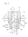
- a suction port 18 and a discharge port 19 are opened in the inner bottom face 4a of the bottom wall 4 which faces the liquid chamber 9 so as to communicate with the inflow passage 5 and the outflow passage 6, respectively.
- a suction check valve 20 is disposed in the suction port 18, and a discharge check valve 21 is disposed in the outflow passage 6.
- the suction check valve 20 is configured by a cylindrical valve casing 201 and valve elements 202 each formed by a ball.
- the valve casing 201 is firmly fixed to the suction port 18 with setting the axis D of the casing vertical, by screwing, engaging means, etc.
- the illustrated suction check valve 20 has a structure in which the valve elements 202 are vertically arranged in two stages.
- the valve casing 201 is divided into vertical halves or a first valve casing 201a and a second valve casing 201b.
- a first valve element 202a and a second valve element 202b are disposed in the first valve casing 201a and the second valve casing 201b, respectively.
- the first valve casing 201a is formed into a cylindrical shape, and an inlet 203 is opened in the lower end.
- An external thread portion 204 which is disposed in the outer periphery of the casing is screwed into an internal thread portion 205 which is disposed in a lower step side of the inner periphery of the suction port 18 of the bottom wall 4, whereby the first valve casing is fixed to the bottom wall 4 with setting the axis D vertical.
- the second valve casing 201b is formed into a cylindrical shape which is larger in diameter than the first valve casing 201a, and an outlet 206 is opened in the upper end.
- An external thread portion 207 which is disposed in the outer periphery of the lower end of the casing is screwed into an internal thread portion 208 which is disposed in an upper step side of the inner periphery of the suction port 18 of the bottom wall 4 so that the diameter is larger than the inner diameter of the internal thread portion 205, and an internal thread portion 209 disposed in the outer periphery of the lower end thereof is screwed onto an external thread portion 210 of the upper end of the outer periphery of the first valve casing 201a, whereby the second valve casing is fixed to the bottom wall 4 so as to be concentrical with the first valve casing 201a and protrude into the liquid chamber 9.
- a valve seat element 212 having a valve seat 211 is incorporated between the upper end of the first valve casing 201a and the lower end of the inner periphery of the second valve casing 201b.
- a valve seat 213 is disposed in an open end of the inflow passage 5 which faces the inlet 203 in the lower end of the first valve casing 201a.
- the first and second valve casings 201a and 201b, and the first and second valve elements 202a and 202b are molded by the same material as the bellows 7, or a fluororesin which has excellent heat and chemical resistances, such as PTFE or PFA.
- the first valve element 202a is caused by its own weight to be closely contacted with the valve seat 213 in the first valve casing 201a
- the second valve element 202b is caused by its own weight to be closely contacted with the valve seat 211 in the second valve casing 201b, thereby preventing liquid from reversely flowing.
- valve elements 202a and 202b When liquid is to be sucked, the first and second valve elements 202a and 202b are respectively upward separated from the valve seats 213 and 211, to open the valve, and the liquid supplied from the inflow passage 5 is sucked into the liquid chamber 9 from the outlet 206 of the second valve casing 201b with passing between a vertical groove 214 formed in the inner periphery of the first valve casing 201a and the first valve element 202a, and a vertical groove 215 formed in the inner periphery of the second valve casing 201b and the second valve element 202b.
- valve elements are vertically arranged in two stages in a valve casing which can be divided into vertical halves.
- each of the suction check valve 20 and the discharge check valve 21 comprises the valve elements vertically arranged in two stages to constitute a double closing structure.
- This structure is advantageous because quantitative supply of the transported liquid can be ensured.
- the valves are not restricted to such a double closing structure.
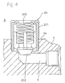
- both or one of the suction check valve 20 and the discharge check valve 21 is configured by a single valve element.
- the suction check valve 20 and the discharge check valve 21 may be employed that, in place of the valve structure due to the gravity type balls, are configured by a valve structure in which, as shown in Fig. 4, the valve element 202 and a spring 300 for urging the valve element 202 against a valve seat are incorporated into the valve casing 201.
- the piston 12 When the pressurized air which is fed from the pressurized air supplying device (not shown) such as a compressor is supplied to the interior of the cylinder 11 via the air hole 14, the piston 12 is raised in the direction x in Fig. 1, and the bellows 7 extends in the same direction to suck the transported liquid in the inflow passage 5 into the liquid chamber 9 via the suction check valve 20.
- the pressurized air is supplied into the air chamber 10 via the air hole 15 and air is discharged through the air hole 14, the piston 12 is lowered in the direction y in Fig. 1, and the bellows 7 contracts in the same direction to discharge the transported liquid in the liquid chamber 9 via the discharge check valve 21.
- the suction check valve 20 and the discharge check valve 21 are alternately opened and closed, so that suction of the transported liquid from the inflow passage 5 into the liquid chamber 9, and discharge of the transported liquid from the liquid chamber 9 to the outflow passage 6 are alternately repeated to conduct a predetermined pumping action.
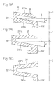
- the invention is characterized in that the extending and contracting portion of the bellows 7 which is configured by forming ridge-like folds 71 and valley-like folds 72 in a vertically alternate and continuous manner is formed into a shape in which the lower one of upper and lower lamella portions 71a and 71b of each of the ridge-like folds 71, or the lower lamella portion 71b is downward inclined as moving toward the axis B, not only in an extending state but also in a contracting state as shown in Figs. 5A, 5B, and 5C.
- the inclination angle ⁇ of the lower lamella portion 71b i.e., the angle ⁇ formed by a horizontal line L perpendicular to the axis B is 1 to 45°, and more preferably 5 to 15°.
- the upper lamella portion 71a of each ridge-like fold 71 may be arbitrarily formed into one of the following shapes in the contracting state: a shape in which, as shown in Fig. 5A, the upper lamella portion is downward inclined at the same inclination angle as the lower lamella portion 71b; that in which, as shown in Fig.
- the upper lamella portion is horizontally formed in parallel with the horizontal line L perpendicular to the axis B; and that in which, as shown in Fig. 5C, the upper lamella portion is upward inclined as moving toward the axis B.
- edges of the folded portion of each of the ridge-like folds 71 and the valley-like folds 72 are angled. Alternatively, the edges may be rounded (as indicated by the two-dot chain lines R).
- the inner bottom face 4a of the liquid chamber 9 is formed into a shape in which, as shown in Fig. 6, the face is downward inclined by 1 to 45°, and more preferably 5 to 15° as moving toward the discharge port 19, and the discharge port 19 is formed in the lowest position of the inner bottom face 4a which is preferably formed into a conical shape.
- the discharge port 19 is on the axis B of the bellows 7 or in a position deviated from the axis B.
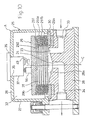
- accumulator body having: a cylindrical casing 27 in which an upper end is closed by an upper wall 26; and a bottom wall 28 which airtightly closes an open lower end of the casing 27.
- a bottomed cylindrical bellows 29 which is extendingly and contractingly deformable in a direction of the axis C is placed in the casing 27 with setting the axis C vertical.
- the bellows 29 is molded by a fluororesin which has excellent heat and chemical resistances, such as PTFE or PFA.
- a lower opening peripheral edge 29a of the bellows is airtightly pressingly fixed to an upper side face of the bottom wall 28 by an annular fixing plate 30, whereby the inner space of the accumulator body 25 is partitioned into a liquid chamber 31 inside the bellows 29, and an air chamber 32 outside the bellows 29.
- a liquid inflow passage 33 and a liquid outflow passage 34 are formed in the bottom wall 28 of the accumulator body 25, and an inflow port 23 and an outflow port 24 are opened in the inner bottom face 28a of the bottom wall 28 which faces the liquid chamber 31 so as to communicate with the inflow passage 33 and the outflow passage 34, respectively.
- the accumulator A is used with being placed in a pipe line for a transported liquid in the pump P of the first embodiment in order to reduce pulsations of the pump P.
- the inflow passage 33 is connected to the downstream end side of the outflow passage 6 of the pump P so that the transported liquid discharged via the discharge check valve 21 of the pump P is temporarily stored in the liquid chamber 31, and the air chamber 32 is filled with air for reducing pulsations of the pump P. Therefore, the accumulator is configured so that pulsations caused by the discharge pressure of the transported liquid discharged from the liquid chamber 9 of the pump P is absorbed and damped by the capacity change of the liquid chamber 31 due to extending and contracting deformation of the bellows 29.
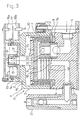
- an opening 35 for allowing air to inflow and outflow is formed in the vicinity of the center of the outer face of the upper wall 26 of the casing 27 of the accumulator A, a valve case 37 having a flange 36 is fitted into the opening 35, and the flange 36 is detachably fastened and fixed to the outside of the upper wall 26 by bolts 38 and the like.
- An air supply port 39 and an air discharge port 40 are formed in the valve case 37 so as to be juxtaposed in parallel.
- An automatic air supply valve mechanism 41 is disposed in the air supply port 39.
- the air supply valve mechanism supplies air of a pressure which is equal to or higher than the maximum pressure of the transported liquid, into the air chamber 32, thereby raising the filling pressure in the air chamber 32.
- An automatic air discharge valve mechanism 42 is disposed in the air discharge port 40.
- the air discharge valve mechanism discharges air from the air chamber 32 to lower the filling pressure in the air chamber 32.
- the automatic air supply valve mechanism 41 comprises: an air supply valve chamber 43 which is formed in the valve case 37 so as to communicate with the air supply port 39; an air supply valve element 44 which is slidable in the valve chamber 43 along the axial direction of the chamber to open and close the air supply port 39; a spring 45 which always urges the valve element 44 to the closing position; a guide member 48 having, in an inner end portion, a valve seat 46 for the air supply valve element 44, and a through hole 47 through which the air supply valve chamber 43 and the air chamber 32 communicate with each other, the valve case being screwingly fixed to the valve case 37; and a valve operating rod 49 which is slidably passed through the through hole 47 of the guide member 48.
- the automatic air discharge valve mechanism 42 comprises: an air discharge valve chamber 50 which is formed in the valve case 37 so as to communicate with the air discharge port 40; an air discharge valve element 51 which is slidable in the valve chamber 50 along the axial direction of the chamber to open and close the air discharge port 40; an air discharge valve rod 53 in which the valve element 51 is disposed at the tip end, and a flange 52 is disposed at the rear end; a spring receiver 55 screwingly fixed into the air discharge valve chamber 50, and having a through hole 54 through which the air discharge valve rod 53 is passed; a cylindrical slider 56 through which a rear end portion of the air discharge valve rod 53 is slidably passed, and which is prevented by the flange 52 from slipping off; a closing spring 57 which is disposed between the air discharge valve element 51 and the spring receiver 55; and an opening spring 58 which is disposed between the spring receiver 55 and the slider 56.
- the inner diameter of the through hole 54 of the spring receiver 55 is larger than the shaft diameter of the air discharge valve rod 53, so as to form a gap 59 between the two components.
- the air discharge valve chamber 50 and the air chamber 32 communicate with each other via the gap 59.
- the air discharge valve element 51 closes the air discharge port 40, and the flange 52 at the rear end of the air discharge valve rod 53 is separated from the inner face of a closing end portion 56a of the slider 56 by a stroke F.
- an end of the valve case 37 on the side of the air chamber is elongated in the direction of the interior of the air chamber 32, and a stopper 61 is disposed at the end of the elongated portion.
- the pump discharge pressure When the transported liquid is fed to a predetermined portion by the operation of the pump P, for example, the pump discharge pressure generates pulsations due to repetition of peak and valley portions.
- the transported liquid discharged from the liquid chamber 9 of the pump P via the discharge check valve 21 is passed through the inflow passage 33 and the inflow port 23 of the accumulator and then sent into the liquid chamber 31.
- the liquid is temporarily stored in the liquid chamber 31, and thereafter discharged into the outflow passage 34 via the outflow port 24.
- the transported liquid causes the bellows 29 to be extendingly deformed so as to increase the capacity of the liquid chamber 31, and hence the pressure of the liquid is absorbed.
- the flow quantity of the transported liquid flowing out from the liquid chamber 31 is smaller than that of the liquid supplied from the pump P.
- the amount of extending deformation of the bellows 29 is restricted so as not to exceed the stroke E, whereby the capacity of the liquid chamber 31 is suppressed from being excessively increased.
- the stopper 61 is disposed at the end of the valve case 37 on the side of the air chamber, the closed upper end portion 29b of the bellows 29 abuts against the stopper 61, so that the bellows 29 can be surely prevented from being excessively extendingly deformed. This is advantageous to prevent the bellows from being damaged.
- the bellows 29 contracts toward the reference position S. Therefore, the valve operating rod 49 separates from the closed upper end portion 29b of the bellows 29, and the air supply valve element 44 returns to the closing position, so that the filling pressure in the air chamber 32 is fixed to an adjusted state.
- the slider 56 of the automatic air discharge valve mechanism 42 is moved in the contraction direction b of the bellows 29 by the urging function of the opening spring 58, in accordance with the movement of the closed upper end portion 29b of the bellows 29 in the contraction direction b, and the inner face of the closing end portion 56a of the slider 56 is engaged with the flange 52 of the air discharge valve rod 53.
- the air discharge valve element 51 again closes the air discharge port 40 by the urging function of the closing spring 57, whereby the filling pressure in the air chamber 32 is fixed to the adjusted state.
- pulsations are efficiently absorbed and the amplitude of pulsations is suppressed to a low level, irrespective of variation of the discharge pressure from the liquid chamber 9 of the pump P.
- the invention in the same manner as the embodiment of the pump P described above, is characterized in that the extending and contracting portion of the bellows 29 which is configured by forming ridge-like folds 291 and valley-like folds 292 in a vertically alternate and continuous manner is formed into a shape in which the lower one of upper and lower lamella portions 291a and 291b of each of the ridge-like folds 291, or the lower lamella portion 291b is downward inclined as moving toward the axis C, not only in an extending state, but also in a contracting state as shown in Figs. 9A, 9B, and 9C.
- the inclination angle ⁇ of the lower lamella portion 291b i.e., the angle ⁇ formed by a horizontal line L perpendicular to the axis C is 1 to 45°, and more preferably 5 to 15°.
- the upper lamella portion 291a of each ridge-like fold 291 may be arbitrarily formed into one of the following shapes in the contracting state: a shape in which, as shown in Fig. 9A, the upper lamella portion is downward inclined at the same inclination angle as the lower lamella portion 291b; that in which, as shown in Fig.
- the upper lamella portion is horizontally formed in parallel with the horizontal line L perpendicular to the axis C; and that in which, as shown in Fig. 9C, the upper lamella portion is upward inclined as moving toward the axis C.
- edges of the folded portion of each of the ridge-like folds 291 and the valley-like folds 292 are angled. Alternatively, the edges may be rounded (as indicated by the two-dot chain lines R).
- the inner bottom face 28a of the liquid chamber 31 is formed into a shape in which, as shown in Fig. 10, the face is downward inclined by 1 to 45°, and more preferably 5 to 15° as moving toward the outflow port 24, and the outflow port 24 is formed in the lowest position of the inner bottom face 28a which is preferably formed into a conical shape.
- the outflow port 24 is on the axis C of the bellows 29 or in a position deviated from the axis C.
- an automatic pressure adjusting mechanism configured by an automatic air supply valve mechanism 41 and an automatic air discharge valve mechanism 42 is provided in the air chamber 32.
- a mechanism of the following configuration may be employed as the automatic pressure adjusting mechanism.
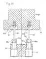
- an opening 35 is formed in the vicinity of the center of the upper wall 26 of the casing 27 of the accumulator, a valve case 37 into which air supply and discharge valves are incorporated is fitted into the opening 35, and the flange 36 attached to the outer periphery of the rear end of the valve case 37 is detachably fastened and fixed to the upper wall 26 by bolts and the like.
- an air supply/discharge valve control plate 70 is abuttingly placed in a center area of the closed upper end portion 29b of the bellows 29 facing the air chamber 32, so as to be opposed to the valve case 37.
- an air supply port 39 and an air discharge port 40 are juxtaposed in the front end face of the valve case 37.
- the automatic air supply valve mechanism 41 is disposed in the air supply port 39.
- the automatic air supply valve mechanism supplies air of a pressure which is higher than the maximum pressure of the transported liquid, into the air chamber 32, thereby raising the filling pressure in the air chamber 32.
- the automatic air discharge valve mechanism 42 is disposed in the air discharge port 40.
- the automatic air discharge valve mechanism discharges air from the air chamber 32, thereby lowering the filling pressure in the air chamber 32.
- an internal thread portion 171 is formed in the rear end face of the valve case 37 so as to communicate with the air supply port 39, and an air supply valve holder 172 which holds an air supply valve element 44 and a valve rod 49 that is integral with the valve element is screwingly fixed to the internal thread portion 171 via an O-ring 73.
- an air supply valve chamber 43 is formed in a front side end portion which is screwed into the internal thread portion 171
- a valve seat 46 is formed in the inner bottom of the air supply valve chamber 43
- a valve rod passing hole 74 is formed in the rear end portion so as to coaxially communicate with the air supply valve chamber 43.
- a plurality of communication holes 75 through which the air supply valve chamber 43 communicates with the air chamber 32 via the valve rod passing hole 74 are formed in the outer periphery of the rear end portion of the air supply valve holder 172.
- the formation of the communication holes 75 improves the responsibility to a pressure change in the air chamber 32.
- an air supply valve 36 is incorporated into the air supply valve chamber 43 so as to be movable in the axial direction, and the valve rod 49 is passed through the valve rod passing hole 74.
- a rear end portion of the valve rod 49 protrudes into the rear of the air supply valve holder 172.
- the valve rod passing hole 74 is formed into a stepped shape having: a larger diameter hole portion 74a in which the inner diameter is larger than the outer diameter of the valve rod 49 to form a communication gap between the hole portion and the valve rod 49; and a guide hole portion 74b which is slightly larger than the outer diameter of the valve rod 49 and slidingly contacted with the valve rod 49 without leaving a substantial gap therebetween.
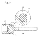
- the air supply valve element 44 In the air supply valve chamber 43, the air supply valve element 44 is always urged by a spring 45 so as to be in the closing position where the element is closely contacted with the valve seat 46.
- the air supply valve element 44 is airtightly contacted with the valve seat 46 via an O-ring 76.
- the O-ring 76 As shown in Fig. 14, the O-ring 76 is fitted into an arcuate groove 77 formed in a corner portion of the rear end face of the air supply valve element 44, whereby the O-ring is lockedly attached to the valve element.
- the air supply valve element 44 is closely contacted with the valve seat 46 of the valve rod holder 172 to close the air supply port 39, and an end portion 49a of the valve rod 49 facing the interior of the air chamber 32 is separated from the closed upper end portion 29b of the bellows 29 by a predetermined stroke.
- an air discharge valve chamber 50 having a circular section shape, and an internal thread portion 78 having an inner diameter which is larger than that of the air discharge valve chamber 50 are formed in the rear end face of the valve case 37 so as to coaxially communicate with the air discharge port 40.
- the air discharge valve element 51 having a shape in which flat faces 51a are formed in opposing portions on the circumference as shown in Fig. 14 is incorporated in the air discharge valve chamber 50 so as to be movable along the axial direction.
- the air discharge valve rod 53 is integrally coupled to the air discharge valve element 51.
- the air discharge valve rod 53 is passed through and held by a valve rod guide hole portion 79a so as to be slidable in the axial direction.
- the valve rod guide hole portion 79a is in the center of a discharge valve rod holder 79 which is screwingly fixed to the internal thread portion 78.
- a plurality of communication holes 80 through which the air discharge valve chamber 50 communicates with the air chamber 32 are formed on the same circle that is centered at the valve rod guide hole portion 79a.
- a spring 81 through which the air discharge valve rod 53 is passed is interposed between the air discharge valve element 51 and the air discharge valve rod holder 79.
- the air discharge valve element 51 is always urged by the spring 81 so as to be in the closing position where the element is closely contacted with the valve seat 50a of the air discharge valve chamber 50.
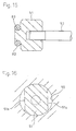
- the air discharge valve element 51 is airtightly contacted with the valve seat 50a via an O-ring 82.
- the O-ring 82 is fitted into an arcuate groove 83 formed in a corner portion of the front end face of the air discharge valve element 51, whereby the O-ring is lockedly attached to the valve element.
- the air discharge valve element 51 closes the air discharge port 40, and a flange 53a in the rear end of the air discharge valve rod 53 is separated from the inner face of a closed end portion 84a of a sleeve 84 by a predetermined stroke.
- the air supply/discharge valve control plate 70 which is abuttingly placed in the center area of the closed upper end portion 29b of the bellows 29 is formed into a disk-like shape, an air supply valve rod pressing portion 85 is recessed in the front face of the plate, and the sleeve 84 constituting an air discharge valve rod pulling portion 86 is fittingly fixed in juxtaposition with the air supply valve rod pressing portion 85.
- a guide hole portion 84a which is slightly larger than the outer diameter of the air discharge valve rod 53 and slidingly contacted with the valve rod 53 without leaving a substantial gap therebetween is formed in a front end portion of the sleeve 84.
- the rear end portion of the air discharge valve rod 53 having the flange 53a is passed through and coupled to the guide hole portion 84a in a slidable and slipping-off preventing manner.
- the air discharge valve rod 53 can be straightly moved along the axial direction.
- the sleeve 84 may be formed integrally with the air supply/discharge valve control plate 70.
- Springs 87 each consisting of a compression coil spring are interposed between the air supply valve rod pressing portion 85 of the air supply/discharge valve control plate 70 and the rear end portion of the air supply valve holder 172, and the sleeve 84 and the rear end face of the air discharge valve rod holder 79, so as to surround the outer peripheries of the air supply valve rod 49 and the air discharge valve rod 53, respectively.
- the air supply/discharge valve control plate 70 is urged by the springs 87 and 87 to be pressed toward the center area of the closed upper end portion 29b of the bellows 29.
- the air supply/discharge valve control plate 70 and the valve case 37 are coupled to each other by one, or preferably plural guide shafts 88 which are parallel to the extending and contracting directions of the bellows 29.
- the front end portion is fasteningly fixed to the rear end face of the valve case 37 by a nut 89 via a washer 89a
- the rear end portion having a flange 88a is coupled to a guide sleeve 90 which is embeddedly fixed to the front end face of the air supply/discharge valve control plate 70, so as to be prevented from slipping off, and slidable in the axial direction.
- each of the guide sleeves 90 In the front end portion of each of the guide sleeves 90, a guide hole portion 90a which is slidingly contacted with the corresponding guide shaft 88 without leaving a substantial gap therebetween is formed.
- the rear end portions of the guide shafts 88 are passed through the guide hole portions 90a, thereby enabling the air supply/discharge valve control plate 70 to be straightly moved in parallel with the extending and contracting directions of the bellows 29 under guidance of the guide shafts 88.
- the guide sleeves 90 may be formed integrally with the air supply/discharge valve control plate 70.
- the air supply valve rod pressing portion 85 of the air supply/discharge valve control plate 70 does not push the rear end portion of the air supply valve rod 49, and the air supply valve element 44 is set to the closing state by the spring 45 and the compressed air in the air chamber 32, so as to balance with the fluid pressure in the liquid chamber 31.
- the closed upper end portion 29b of the bellows strikes against a stopper wall 27a of the casing 27 of the accumulator A which protrudes into the air chamber 32, whereby excessive extending deformation of the bellows 29 is restricted, so that the bellows can be prevented from being damaged.
- the air discharge valve rod 53 which is coupled to the discharge valve rod pulling portion 86 of the air supply/discharge valve control plate 70 is pulled in the same direction, whereby the air discharge valve element 51 is changed to the opening state. Therefore, the compressed air in the air chamber 32 is discharged to the atmosphere from the air discharge port 40 to lower the filling pressure in the air chamber 32. In accordance with the reduction of the filling pressure in the air chamber 32, the bellows 29 is extended. Then, the air supply/discharge valve control plate 70 is pushed by the center area of the closed upper end portion 29b of the bellows 29, and the air discharge valve element 51 is caused to close the air discharge port 40 by the urging action of the spring 81. As a result, the filling pressure in the air chamber 32 is fixed to the adjusted state.
- the air supply valve element 44 and the air discharge valve element 51 which are separately and independently disposed in the valve case 37 are subjected to the valve-opening control in accordance with expansion and contraction of the bellows 29, via the air supply valve rod pressing portion 85 and the air discharge valve rod pulling portion 86 on the air supply/discharge valve control plate 70. Since the air supply/discharge valve control plate 70 is placed so as to always abut against the center area of the closed upper end portion 29b of the bellows 29, no offset load is applied to the bellows 29 even when the air supply valve element 44 and the air discharge valve element 51 are juxtaposed separately and independently in the valve case 37.
- the bellows 29 is always straightly extendingly and contractingly deformed in the axial direction X-X of the valve case 37, whereby the responsibility of the opening and closing operations of the air supply and discharge valve elements 44 and 51 can be improved and the performance of reducing pulsations can be ensured.
- the air supply/discharge valve control plate 70 can be always enabled to be moved in parallel stably and surely by the guiding action of the guide shafts 88. Consequently, the air supply and discharge valve elements 44 and 51 can faithfully perform the opening and closing operations corresponding to expansion and contraction of the bellows 29, via the air supply/discharge valve control plate 70.
- the automatic pressure adjusting mechanism consisting of the automatic air supply valve mechanism 41 and the automatic air discharge valve mechanism 42 is attached to the air chamber 32.
- the air chamber 32 is required only to have the opening 35 for allowing air to inflow and outflow, and is not always requested to have the automatic pressure adjusting mechanism.
- the pressure adjustment may be manually performed.
- the sedimenting material can be effectively prevented from sedimenting and aggregating in a pump or an accumulator.
Landscapes
- Engineering & Computer Science (AREA)
- Mechanical Engineering (AREA)
- General Engineering & Computer Science (AREA)
- Physics & Mathematics (AREA)
- Fluid Mechanics (AREA)
- Reciprocating Pumps (AREA)
- Supply Devices, Intensifiers, Converters, And Telemotors (AREA)
- Diaphragms And Bellows (AREA)
- Details Of Reciprocating Pumps (AREA)
Applications Claiming Priority (3)
| Application Number | Priority Date | Filing Date | Title |
|---|---|---|---|
| JP33756299A JP2001153053A (ja) | 1999-11-29 | 1999-11-29 | ベローズを有する流体機器 |
| JP33756299 | 1999-11-29 | ||
| PCT/JP2000/008159 WO2001040651A1 (fr) | 1999-11-29 | 2000-11-20 | Dispositif d'ecoulement de fluide a soufflet |
Publications (3)
| Publication Number | Publication Date |
|---|---|
| EP1156217A1 true EP1156217A1 (de) | 2001-11-21 |
| EP1156217A4 EP1156217A4 (de) | 2010-07-28 |
| EP1156217B1 EP1156217B1 (de) | 2012-07-04 |
Family
ID=18309822
Family Applications (1)
| Application Number | Title | Priority Date | Filing Date |
|---|---|---|---|
| EP00976354A Expired - Lifetime EP1156217B1 (de) | 1999-11-29 | 2000-11-20 | Fluidvorrichtung mit balg |
Country Status (6)
| Country | Link |
|---|---|
| US (1) | US6945761B1 (de) |
| EP (1) | EP1156217B1 (de) |
| JP (1) | JP2001153053A (de) |
| KR (1) | KR100460971B1 (de) |
| TW (1) | TW466303B (de) |
| WO (1) | WO2001040651A1 (de) |
Cited By (3)
| Publication number | Priority date | Publication date | Assignee | Title |
|---|---|---|---|---|
| WO2008089908A1 (de) * | 2007-01-25 | 2008-07-31 | Elringklinger Ag | Strukturbauteil |
| CN106795876A (zh) * | 2014-08-08 | 2017-05-31 | 日本皮拉工业株式会社 | 波纹管泵装置 |
| CN110177944A (zh) * | 2017-02-03 | 2019-08-27 | 伊格尔工业股份有限公司 | 液体供给系统 |
Families Citing this family (2)
| Publication number | Priority date | Publication date | Assignee | Title |
|---|---|---|---|---|
| US20100178182A1 (en) * | 2009-01-09 | 2010-07-15 | Simmons Tom M | Helical bellows, pump including same and method of bellows fabrication |
| US8636484B2 (en) * | 2009-01-09 | 2014-01-28 | Tom M. Simmons | Bellows plungers having one or more helically extending features, pumps including such bellows plungers, and related methods |
Citations (4)
| Publication number | Priority date | Publication date | Assignee | Title |
|---|---|---|---|---|
| GB488579A (en) * | 1936-01-11 | 1938-07-11 | Adolf Brendlin | Improvements in bellows |
| JPS58170866A (ja) * | 1982-03-02 | 1983-10-07 | Seven Ribaa:Kk | ベロ−ズポンプ |
| JPS61262531A (ja) * | 1985-05-14 | 1986-11-20 | Daikin Ind Ltd | 空気調和機のドレン装置 |
| EP0943799A2 (de) * | 1998-03-20 | 1999-09-22 | Nippon Pillar Packing Co. Ltd. | Pulsationsdämpfer für eine Pumpe |
Family Cites Families (11)
| Publication number | Priority date | Publication date | Assignee | Title |
|---|---|---|---|---|
| US2021156A (en) * | 1933-11-10 | 1935-11-19 | Smith William Neil | Pump |
| US3394631A (en) * | 1965-10-23 | 1968-07-30 | Tom H. Thompson | Bellows mechanism |
| US4231724A (en) * | 1978-03-09 | 1980-11-04 | Hope Henry F | Adjustable metering pump |
| DE3326250A1 (de) * | 1983-07-21 | 1985-01-31 | Lang Apparatebau GmbH, 8227 Siegsdorf | Faltenbalgpumpe |
| US4984970A (en) * | 1986-10-22 | 1991-01-15 | Karl Eickmann | Arrangements on coned rings which are applicable in high pressure pumps and related devices |
| JPH03179184A (ja) | 1989-12-05 | 1991-08-05 | Nippon Pillar Packing Co Ltd | 往復動ポンプ |
| JPH05302573A (ja) * | 1992-04-27 | 1993-11-16 | Hideo Nagamitsu | ベローズ式圧縮装置 |
| JPH0617752A (ja) | 1992-07-01 | 1994-01-25 | Iwaki:Kk | 脈動減少装置 |
| JP2573154B2 (ja) | 1994-04-01 | 1997-01-22 | 日本ピラー工業株式会社 | ベローズ式定量ポンプ |
| JP2808415B2 (ja) | 1994-12-12 | 1998-10-08 | 日本ピラー工業株式会社 | ポンプの脈動幅抑制装置 |
| FR2772436B1 (fr) * | 1997-12-16 | 2000-01-21 | Centre Nat Etd Spatiales | Pompe a deplacement positif |
-
1999
- 1999-11-29 JP JP33756299A patent/JP2001153053A/ja active Pending
-
2000
- 2000-11-20 EP EP00976354A patent/EP1156217B1/de not_active Expired - Lifetime
- 2000-11-20 WO PCT/JP2000/008159 patent/WO2001040651A1/ja active IP Right Grant
- 2000-11-20 US US09/868,938 patent/US6945761B1/en not_active Expired - Lifetime
- 2000-11-20 KR KR10-2001-7009051A patent/KR100460971B1/ko active IP Right Grant
- 2000-11-23 TW TW089124950A patent/TW466303B/zh not_active IP Right Cessation
Patent Citations (4)
| Publication number | Priority date | Publication date | Assignee | Title |
|---|---|---|---|---|
| GB488579A (en) * | 1936-01-11 | 1938-07-11 | Adolf Brendlin | Improvements in bellows |
| JPS58170866A (ja) * | 1982-03-02 | 1983-10-07 | Seven Ribaa:Kk | ベロ−ズポンプ |
| JPS61262531A (ja) * | 1985-05-14 | 1986-11-20 | Daikin Ind Ltd | 空気調和機のドレン装置 |
| EP0943799A2 (de) * | 1998-03-20 | 1999-09-22 | Nippon Pillar Packing Co. Ltd. | Pulsationsdämpfer für eine Pumpe |
Non-Patent Citations (1)
| Title |
|---|
| See also references of WO0140651A1 * |
Cited By (6)
| Publication number | Priority date | Publication date | Assignee | Title |
|---|---|---|---|---|
| WO2008089908A1 (de) * | 2007-01-25 | 2008-07-31 | Elringklinger Ag | Strukturbauteil |
| CN106795876A (zh) * | 2014-08-08 | 2017-05-31 | 日本皮拉工业株式会社 | 波纹管泵装置 |
| EP3179105A4 (de) * | 2014-08-08 | 2018-02-14 | Nippon Pillar Packing Co., Ltd. | Balgpumpenvorrichtung |
| US10309391B2 (en) | 2014-08-08 | 2019-06-04 | Nippon Pillar Packing Co., Ltd. | Bellows pump device |
| CN106795876B (zh) * | 2014-08-08 | 2019-06-11 | 日本皮拉工业株式会社 | 波纹管泵装置 |
| CN110177944A (zh) * | 2017-02-03 | 2019-08-27 | 伊格尔工业股份有限公司 | 液体供给系统 |
Also Published As
| Publication number | Publication date |
|---|---|
| TW466303B (en) | 2001-12-01 |
| JP2001153053A (ja) | 2001-06-05 |
| EP1156217B1 (de) | 2012-07-04 |
| KR100460971B1 (ko) | 2004-12-09 |
| EP1156217A4 (de) | 2010-07-28 |
| WO2001040651A1 (fr) | 2001-06-07 |
| KR20010101581A (ko) | 2001-11-14 |
| US6945761B1 (en) | 2005-09-20 |
Similar Documents
| Publication | Publication Date | Title |
|---|---|---|
| US4594059A (en) | Diaphragm pump | |
| US6364640B1 (en) | Pump with a pulsation suppression device | |
| EP1156216B1 (de) | Fluidvorrichtung mit balg | |
| US6488487B2 (en) | Pulsation damping device | |
| US6572347B2 (en) | Fluid apparatus such as a pump or an accumulator | |
| EP1156217B1 (de) | Fluidvorrichtung mit balg | |
| EP1156219B1 (de) | Fluidvorrichtung wie pumpe und speicher | |
| US7284970B2 (en) | Fluid apparatus having a pump and an accumulator | |
| EP1156218B1 (de) | Fluidvorrichtung mit balgen | |
| JPH0735035A (ja) | ポンプ | |
| JP3962716B2 (ja) | ベローズを有する流体機器及びその流体機器内の残留空気排出方法 | |
| JP4478394B2 (ja) | ポンプ等の流体機器 |
Legal Events
| Date | Code | Title | Description |
|---|---|---|---|
| PUAI | Public reference made under article 153(3) epc to a published international application that has entered the european phase |
Free format text: ORIGINAL CODE: 0009012 |
|
| 17P | Request for examination filed |
Effective date: 20010802 |
|
| AK | Designated contracting states |
Kind code of ref document: A1 Designated state(s): AT BE CH CY DE DK ES FI FR GB GR IE IT LI LU MC NL PT SE TR |
|
| RBV | Designated contracting states (corrected) |
Designated state(s): DE FR GB |
|
| A4 | Supplementary search report drawn up and despatched |
Effective date: 20100625 |
|
| 17Q | First examination report despatched |
Effective date: 20110214 |
|
| REG | Reference to a national code |
Ref country code: DE Ref legal event code: R079 Ref document number: 60047320 Country of ref document: DE Free format text: PREVIOUS MAIN CLASS: F04B0043080000 Ipc: F04B0043000000 |
|
| RIC1 | Information provided on ipc code assigned before grant |
Ipc: F15B 1/10 20060101ALI20110930BHEP Ipc: F04B 43/08 20060101ALI20110930BHEP Ipc: F04B 43/00 20060101AFI20110930BHEP |
|
| GRAP | Despatch of communication of intention to grant a patent |
Free format text: ORIGINAL CODE: EPIDOSNIGR1 |
|
| GRAS | Grant fee paid |
Free format text: ORIGINAL CODE: EPIDOSNIGR3 |
|
| GRAA | (expected) grant |
Free format text: ORIGINAL CODE: 0009210 |
|
| AK | Designated contracting states |
Kind code of ref document: B1 Designated state(s): DE FR GB |
|
| REG | Reference to a national code |
Ref country code: GB Ref legal event code: FG4D |
|
| REG | Reference to a national code |
Ref country code: DE Ref legal event code: R096 Ref document number: 60047320 Country of ref document: DE Effective date: 20120823 |
|
| PLBE | No opposition filed within time limit |
Free format text: ORIGINAL CODE: 0009261 |
|
| STAA | Information on the status of an ep patent application or granted ep patent |
Free format text: STATUS: NO OPPOSITION FILED WITHIN TIME LIMIT |
|
| 26N | No opposition filed |
Effective date: 20130405 |
|
| REG | Reference to a national code |
Ref country code: DE Ref legal event code: R097 Ref document number: 60047320 Country of ref document: DE Effective date: 20130405 |
|
| REG | Reference to a national code |
Ref country code: FR Ref legal event code: PLFP Year of fee payment: 16 |
|
| REG | Reference to a national code |
Ref country code: FR Ref legal event code: PLFP Year of fee payment: 17 |
|
| REG | Reference to a national code |
Ref country code: FR Ref legal event code: PLFP Year of fee payment: 18 |
|
| PGFP | Annual fee paid to national office [announced via postgrant information from national office to epo] |
Ref country code: DE Payment date: 20191121 Year of fee payment: 20 |
|
| PGFP | Annual fee paid to national office [announced via postgrant information from national office to epo] |
Ref country code: FR Payment date: 20191120 Year of fee payment: 20 |
|
| PGFP | Annual fee paid to national office [announced via postgrant information from national office to epo] |
Ref country code: GB Payment date: 20191120 Year of fee payment: 20 |
|
| REG | Reference to a national code |
Ref country code: DE Ref legal event code: R071 Ref document number: 60047320 Country of ref document: DE |
|
| REG | Reference to a national code |
Ref country code: GB Ref legal event code: PE20 Expiry date: 20201119 |
|
| PG25 | Lapsed in a contracting state [announced via postgrant information from national office to epo] |
Ref country code: GB Free format text: LAPSE BECAUSE OF EXPIRATION OF PROTECTION Effective date: 20201119 |