EP1156194A1 - Kurbelgehäuse mit integriertem Entlüftungsraum - Google Patents
Kurbelgehäuse mit integriertem Entlüftungsraum Download PDFInfo
- Publication number
- EP1156194A1 EP1156194A1 EP01106077A EP01106077A EP1156194A1 EP 1156194 A1 EP1156194 A1 EP 1156194A1 EP 01106077 A EP01106077 A EP 01106077A EP 01106077 A EP01106077 A EP 01106077A EP 1156194 A1 EP1156194 A1 EP 1156194A1
- Authority
- EP
- European Patent Office
- Prior art keywords
- crankcase
- spaces
- calming
- crank
- bores
- Prior art date
- Legal status (The legal status is an assumption and is not a legal conclusion. Google has not performed a legal analysis and makes no representation as to the accuracy of the status listed.)
- Granted
Links
Images

Classifications
-
- F—MECHANICAL ENGINEERING; LIGHTING; HEATING; WEAPONS; BLASTING
- F01—MACHINES OR ENGINES IN GENERAL; ENGINE PLANTS IN GENERAL; STEAM ENGINES
- F01M—LUBRICATING OF MACHINES OR ENGINES IN GENERAL; LUBRICATING INTERNAL COMBUSTION ENGINES; CRANKCASE VENTILATING
- F01M13/00—Crankcase ventilating or breathing
- F01M13/04—Crankcase ventilating or breathing having means for purifying air before leaving crankcase, e.g. removing oil
Definitions
- the invention relates to a crankcase with an integrated ventilation space according to the preamble of claim 1.
- the object of the invention is therefore to produce this calming space to make casting technology more advantageous.
- Figure 1 shows in cross section through a crankcase 1 with bore 2 for receiving a wet cylinder liner 3.
- the blow-by from the crank chamber 4 are 1 relaxation rooms on both sides of the crankcase 5a, 5b are provided.
- the Bore 2 turns 6 in which sealing rings are inserted, which after installation of the liners take over the sealing function for the cooling water.
- the crankcase 1 also has a collar 7 which the large seal of the crank chamber 4 against splash oil.
- the separation of the Crank spaces 4 against each other are made by bulkheads 8 which also the storage chairs Record 9.
- each of the crank chambers 4 is now opened in via a window opening 10 the bulkhead 8 and via bilateral transitions 11a and 11b with the calming rooms 5a, 5b connected.
- the blow-by reaches the crank chamber 4 which is open Window opening 10 and the transitions 11a, 11b as with a broken line and arrow shown to the calming rooms 5a, 5b.
- This is the one below the cylinder liner 3 flows around the same lying part as it follows in Figures 3 and 4 is clarified.
- the particular advantage of this ventilation can be seen in rational production.
- the Casting core for the crank chamber 4 and the calming chambers 5a, 5b can be part getting produced.
- the connection of the cores for the crank chamber 4 and the calming rooms 5a, 5b is through the cores for the window opening 11 and the transitions 11a, 11b accomplished.
- the sections of the core can be used for remove the calming areas 5a, 5b slightly.
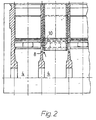
- crankcase 1 shows a longitudinal section II-II through the crankcase 1.
- the bulkhead 8, which separates the crank chambers 4, has the one open to the crank chambers 4 Window openings 10 through which the Blow by indicated by arrows occurs.
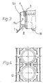
- the blow-by way is shown in detail in half section in FIG. 3.
- the cylinder liner 3 is against the cooling water via sealing rings which are arranged in the grooves 6 sealed.
- a rough seal against the crank chamber 4 is carried out by the Collar 7 and the cylinder liner 3.
- the bulkhead 8 has the against the crankcase open window openings 10, through which the blow by penetrated by arrow penetrates and reaches the calming space 5a via the transition 11a, which is the crankcase 1 penetrates in the longitudinal direction.
- FIG. 4 A top view of the cylinder liners 1 with window openings 10 and the transitions 11a, 11b shows FIG. 4. After casting, the core sand of the connection spaces can 11a, 11b (Fig. 1) through the openings 12 are removed so that openings can be omitted in the side walls of the crankcase 1.
Landscapes
- Engineering & Computer Science (AREA)
- Mechanical Engineering (AREA)
- General Engineering & Computer Science (AREA)
- Lubrication Details And Ventilation Of Internal Combustion Engines (AREA)
- Cylinder Crankcases Of Internal Combustion Engines (AREA)
Abstract
Description
- Fig. 1
- einen Querschnitt I-I durch ein Kurbelgehäuse mit Beruhigungsräumen und einer Fensteröffnung in einer Schottwand
- Fig. 2
- einen Längsschnitt II-II durch das Kurbelgehäuse mit Fensteröffnung in der Schottwand
- Fig. 3
- einen Schnitt III-III mit detaillierter Darstellung der Fensteröffnung und des Übergangs zu einem Beruhigungsraum
- Fig. 4
- einen Schnitt IV-IV mit Draufsicht auf den Strömungsweg des Blow by
Claims (2)
- Kurbelgehäuse mit integriertem Entlüftungsraum, bei dem das Kurbelgehäuse Bohrungen für die Aufnahme von nassen Zylinderlaufbüchsen aufweist, wobei die Bohrungen Nuten für die Abdichtung der Zylinderlaufbüchsen gegen das Kühlwasser aufweisen und das Kurbelgehäuse an beiden Seiten in Längsrichtung verlaufende Beruhigungsräume für den Blow by aufweist, dadurch gekennzeichnet, diese Beruhigungsräume (5a, 5b ) zunächst mittels eines Bundes (7) im Kurbelgehäuse (1) und der Zylinderlaufbüchse (3) gegen den Kurbelraum (4) abgeschottet sind, daß die Verbindung des Kurbelraumes (4) mit den Beruhigungsräumen (5a, 5b) durch Fensteröffnungen (10) in den Schottwänden (8) hergestellt werden, welche gegen den Kurbelraum (4) hin geöffnet sind und diese Fensteröffnungen (10) wiederum über Übergänge (11a, 11b) an den Zylinderlaufbüchsen (1) vorbei mit den Beruhigungsräumen (5a, 5b) in Verbindungen (11a, 11b) stehen.
- Kurbelgehäuse nach Anspruch 1, dadurch gekennzeichnet, daß die Gießkerne für die Beruhigungsräume (5a, 5b) und für die Kurbelräume (4) eine Einheit bilden und daß die Verbindung dieser Teile über die Kerne für die Fensteröffnung (10) und die Übergänge (11a, 11b) bewerkstelligt wird.
Applications Claiming Priority (2)
| Application Number | Priority Date | Filing Date | Title |
|---|---|---|---|
| DE10024218A DE10024218A1 (de) | 2000-05-17 | 2000-05-17 | Kurbelgehäuse mit integriertem Entlüftungsraum |
| DE10024218 | 2000-05-17 |
Publications (2)
| Publication Number | Publication Date |
|---|---|
| EP1156194A1 true EP1156194A1 (de) | 2001-11-21 |
| EP1156194B1 EP1156194B1 (de) | 2005-05-04 |
Family
ID=7642416
Family Applications (1)
| Application Number | Title | Priority Date | Filing Date |
|---|---|---|---|
| EP01106077A Expired - Lifetime EP1156194B1 (de) | 2000-05-17 | 2001-03-13 | Kurbelgehäuse mit integriertem Entlüftungsraum |
Country Status (4)
| Country | Link |
|---|---|
| US (1) | US6477991B2 (de) |
| EP (1) | EP1156194B1 (de) |
| AT (1) | ATE294919T1 (de) |
| DE (2) | DE10024218A1 (de) |
Families Citing this family (3)
| Publication number | Priority date | Publication date | Assignee | Title |
|---|---|---|---|---|
| DE102006028801B4 (de) * | 2006-06-23 | 2017-10-12 | Bayerische Motoren Werke Aktiengesellschaft | Kurbelgehäuse mit einer Ventilationsbohrung |
| KR20230067525A (ko) * | 2021-11-09 | 2023-05-16 | 얀마 홀딩스 주식회사 | 엔진 시스템 |
| US12312984B2 (en) * | 2022-07-28 | 2025-05-27 | Ford Global Technologies, Llc | Cylinder block baffle for separating oil from crankcase gasses |
Citations (4)
| Publication number | Priority date | Publication date | Assignee | Title |
|---|---|---|---|---|
| EP0600341A1 (de) * | 1992-12-02 | 1994-06-08 | Adam Opel Ag | Zylinderkurbelgehäuse für eine Brennkraftmaschine mit darin angeordneten Be- und Entlüftungskanälen |
| DE19736040A1 (de) | 1997-08-20 | 1999-02-25 | Man Nutzfahrzeuge Ag | Vorrichtung zur Abscheidung von Öl aus einen Öl-Gasgemisch von Brennkraftmaschinen |
| EP0940574A2 (de) * | 1998-03-05 | 1999-09-08 | Volkswagen Aktiengesellschaft | Brennkraftmaschine |
| DE19913176A1 (de) * | 1999-03-24 | 2000-09-28 | Fev Motorentech Gmbh | Motorblock mit Ölabscheidung im Entlüftungsbereich |
Family Cites Families (2)
| Publication number | Priority date | Publication date | Assignee | Title |
|---|---|---|---|---|
| GB2260365A (en) * | 1991-10-03 | 1993-04-14 | Jaguar Cars | Oil Separation from i.c. engine crankcase gases |
| US6345614B1 (en) * | 2000-12-27 | 2002-02-12 | Detroit Diesel Corporation | Separator and oil trap for closed crankcase ventilator systems |
-
2000
- 2000-05-17 DE DE10024218A patent/DE10024218A1/de not_active Withdrawn
-
2001
- 2001-03-13 AT AT01106077T patent/ATE294919T1/de not_active IP Right Cessation
- 2001-03-13 EP EP01106077A patent/EP1156194B1/de not_active Expired - Lifetime
- 2001-03-13 DE DE50106071T patent/DE50106071D1/de not_active Expired - Lifetime
- 2001-05-17 US US09/861,135 patent/US6477991B2/en not_active Expired - Lifetime
Patent Citations (4)
| Publication number | Priority date | Publication date | Assignee | Title |
|---|---|---|---|---|
| EP0600341A1 (de) * | 1992-12-02 | 1994-06-08 | Adam Opel Ag | Zylinderkurbelgehäuse für eine Brennkraftmaschine mit darin angeordneten Be- und Entlüftungskanälen |
| DE19736040A1 (de) | 1997-08-20 | 1999-02-25 | Man Nutzfahrzeuge Ag | Vorrichtung zur Abscheidung von Öl aus einen Öl-Gasgemisch von Brennkraftmaschinen |
| EP0940574A2 (de) * | 1998-03-05 | 1999-09-08 | Volkswagen Aktiengesellschaft | Brennkraftmaschine |
| DE19913176A1 (de) * | 1999-03-24 | 2000-09-28 | Fev Motorentech Gmbh | Motorblock mit Ölabscheidung im Entlüftungsbereich |
Also Published As
| Publication number | Publication date |
|---|---|
| US6477991B2 (en) | 2002-11-12 |
| DE10024218A1 (de) | 2001-11-22 |
| US20010050064A1 (en) | 2001-12-13 |
| DE50106071D1 (de) | 2005-06-09 |
| EP1156194B1 (de) | 2005-05-04 |
| ATE294919T1 (de) | 2005-05-15 |
Similar Documents
| Publication | Publication Date | Title |
|---|---|---|
| DE602004006659T2 (de) | Vorrichtung zur Regelung von Kurbelwellengas | |
| DE3542900C2 (de) | ||
| EP1174597B1 (de) | Baugruppe für eine Brennkraftmaschine mit einem Ölfilter | |
| DE3713210C2 (de) | ||
| DE10338807B4 (de) | Entlüftungsvorrichtung für Brennkraftmaschinen | |
| EP2195520A1 (de) | Zylinderkurbelgehäuse für einen verbrennungsmotor | |
| EP1457646B1 (de) | Ölauffangvorrichtung für eine Brennkraftmaschine, insbesondere für einen Boxermotor | |
| DE102007009955A1 (de) | Kurbelgehäuse | |
| DE3923986C1 (de) | ||
| WO2002063144A1 (de) | Ölauffangvorrichtung für eine brennkraftmaschine | |
| DE19701977B4 (de) | Brennkraftmaschine mit einem Ventilkammerdeckel | |
| EP1284342B1 (de) | Ölauffangvorrichtung für eine Brennkraftmaschine, insbesondere für einen Boxermotor | |
| DE19608066C1 (de) | Kurbelraumentlüftung für eine Brennkraftmaschine | |
| DE4029408C2 (de) | Schmierölwärmetauscher einer Brennkraftmaschine | |
| DE3416235A1 (de) | Zylinderkopf fuer eine wassergekuehlte brennkraftmaschine | |
| EP1156194B1 (de) | Kurbelgehäuse mit integriertem Entlüftungsraum | |
| DE2822780A1 (de) | Drehkolbenverdichter | |
| EP0967381B1 (de) | Zylinderkopf einer Brennkraftmaschine | |
| DE4206165A1 (de) | Kurbelgehaeuse fuer eine hubkolben-brennkraftmaschine | |
| DE19608503C2 (de) | Kurbelgehäuseentlüftung für eine Brennkraftmaschine | |
| DE10105555B4 (de) | Entlüftungsvorrichtung für ölbeladene Gase einer Brennkraftmaschine | |
| DE102005048331A1 (de) | Zylinderkopf für eine Brennkraftmaschine | |
| DE19626648A1 (de) | Becherfilter | |
| DE19720383A1 (de) | Entlüftungsvorrichtung für ein Kurbelgehäuse einer Brennkraftmaschine | |
| DE102007014546B4 (de) | Kurbelgehäuse |
Legal Events
| Date | Code | Title | Description |
|---|---|---|---|
| PUAI | Public reference made under article 153(3) epc to a published international application that has entered the european phase |
Free format text: ORIGINAL CODE: 0009012 |
|
| AK | Designated contracting states |
Kind code of ref document: A1 Designated state(s): AT BE CH CY DE DK ES FI FR GB GR IE IT LI LU MC NL PT SE TR |
|
| AX | Request for extension of the european patent |
Free format text: AL;LT;LV;MK;RO;SI |
|
| 17P | Request for examination filed |
Effective date: 20011205 |
|
| AKX | Designation fees paid |
Free format text: AT BE CH CY DE DK ES FI FR GB GR IE IT LI LU MC NL PT SE TR |
|
| GRAP | Despatch of communication of intention to grant a patent |
Free format text: ORIGINAL CODE: EPIDOSNIGR1 |
|
| GRAS | Grant fee paid |
Free format text: ORIGINAL CODE: EPIDOSNIGR3 |
|
| GRAA | (expected) grant |
Free format text: ORIGINAL CODE: 0009210 |
|
| AK | Designated contracting states |
Kind code of ref document: B1 Designated state(s): AT BE CH CY DE DK ES FI FR GB GR IE IT LI LU MC NL PT SE TR |
|
| PG25 | Lapsed in a contracting state [announced via postgrant information from national office to epo] |
Ref country code: IE Free format text: LAPSE BECAUSE OF FAILURE TO SUBMIT A TRANSLATION OF THE DESCRIPTION OR TO PAY THE FEE WITHIN THE PRESCRIBED TIME-LIMIT Effective date: 20050504 Ref country code: FI Free format text: LAPSE BECAUSE OF FAILURE TO SUBMIT A TRANSLATION OF THE DESCRIPTION OR TO PAY THE FEE WITHIN THE PRESCRIBED TIME-LIMIT Effective date: 20050504 |
|
| REG | Reference to a national code |
Ref country code: GB Ref legal event code: FG4D Free format text: NOT ENGLISH |
|
| REG | Reference to a national code |
Ref country code: CH Ref legal event code: EP |
|
| REG | Reference to a national code |
Ref country code: IE Ref legal event code: FG4D Free format text: LANGUAGE OF EP DOCUMENT: GERMAN |
|
| REF | Corresponds to: |
Ref document number: 50106071 Country of ref document: DE Date of ref document: 20050609 Kind code of ref document: P |
|
| PG25 | Lapsed in a contracting state [announced via postgrant information from national office to epo] |
Ref country code: DK Free format text: LAPSE BECAUSE OF FAILURE TO SUBMIT A TRANSLATION OF THE DESCRIPTION OR TO PAY THE FEE WITHIN THE PRESCRIBED TIME-LIMIT Effective date: 20050804 Ref country code: GR Free format text: LAPSE BECAUSE OF FAILURE TO SUBMIT A TRANSLATION OF THE DESCRIPTION OR TO PAY THE FEE WITHIN THE PRESCRIBED TIME-LIMIT Effective date: 20050804 |
|
| PG25 | Lapsed in a contracting state [announced via postgrant information from national office to epo] |
Ref country code: ES Free format text: LAPSE BECAUSE OF FAILURE TO SUBMIT A TRANSLATION OF THE DESCRIPTION OR TO PAY THE FEE WITHIN THE PRESCRIBED TIME-LIMIT Effective date: 20050815 |
|
| REG | Reference to a national code |
Ref country code: SE Ref legal event code: TRGR |
|
| GBT | Gb: translation of ep patent filed (gb section 77(6)(a)/1977) |
Effective date: 20050902 |
|
| PG25 | Lapsed in a contracting state [announced via postgrant information from national office to epo] |
Ref country code: PT Free format text: LAPSE BECAUSE OF FAILURE TO SUBMIT A TRANSLATION OF THE DESCRIPTION OR TO PAY THE FEE WITHIN THE PRESCRIBED TIME-LIMIT Effective date: 20051017 |
|
| REG | Reference to a national code |
Ref country code: IE Ref legal event code: FD4D |
|
| PLBE | No opposition filed within time limit |
Free format text: ORIGINAL CODE: 0009261 |
|
| STAA | Information on the status of an ep patent application or granted ep patent |
Free format text: STATUS: NO OPPOSITION FILED WITHIN TIME LIMIT |
|
| PG25 | Lapsed in a contracting state [announced via postgrant information from national office to epo] |
Ref country code: AT Free format text: LAPSE BECAUSE OF NON-PAYMENT OF DUE FEES Effective date: 20060313 |
|
| ET | Fr: translation filed | ||
| PG25 | Lapsed in a contracting state [announced via postgrant information from national office to epo] |
Ref country code: LU Free format text: LAPSE BECAUSE OF NON-PAYMENT OF DUE FEES Effective date: 20060331 Ref country code: CH Free format text: LAPSE BECAUSE OF NON-PAYMENT OF DUE FEES Effective date: 20060331 Ref country code: BE Free format text: LAPSE BECAUSE OF NON-PAYMENT OF DUE FEES Effective date: 20060331 Ref country code: LI Free format text: LAPSE BECAUSE OF NON-PAYMENT OF DUE FEES Effective date: 20060331 Ref country code: MC Free format text: LAPSE BECAUSE OF NON-PAYMENT OF DUE FEES Effective date: 20060331 |
|
| 26N | No opposition filed |
Effective date: 20060207 |
|
| REG | Reference to a national code |
Ref country code: CH Ref legal event code: PL |
|
| BERE | Be: lapsed |
Owner name: MAN NUTZFAHRZEUGE A.G. Effective date: 20060331 |
|
| PG25 | Lapsed in a contracting state [announced via postgrant information from national office to epo] |
Ref country code: TR Free format text: LAPSE BECAUSE OF FAILURE TO SUBMIT A TRANSLATION OF THE DESCRIPTION OR TO PAY THE FEE WITHIN THE PRESCRIBED TIME-LIMIT Effective date: 20050504 |
|
| PG25 | Lapsed in a contracting state [announced via postgrant information from national office to epo] |
Ref country code: CY Free format text: LAPSE BECAUSE OF FAILURE TO SUBMIT A TRANSLATION OF THE DESCRIPTION OR TO PAY THE FEE WITHIN THE PRESCRIBED TIME-LIMIT Effective date: 20050504 |
|
| REG | Reference to a national code |
Ref country code: NL Ref legal event code: TD Effective date: 20110304 |
|
| REG | Reference to a national code |
Ref country code: FR Ref legal event code: CD |
|
| REG | Reference to a national code |
Ref country code: DE Ref legal event code: R081 Ref document number: 50106071 Country of ref document: DE Owner name: MAN TRUCK & BUS AG, DE Free format text: FORMER OWNER: MAN NUTZFAHRZEUGE AG, 80995 MUENCHEN, DE Effective date: 20110406 |
|
| REG | Reference to a national code |
Ref country code: FR Ref legal event code: PLFP Year of fee payment: 16 |
|
| PG25 | Lapsed in a contracting state [announced via postgrant information from national office to epo] |
Ref country code: IT Free format text: LAPSE BECAUSE OF NON-PAYMENT OF DUE FEES Effective date: 20160313 |
|
| REG | Reference to a national code |
Ref country code: FR Ref legal event code: PLFP Year of fee payment: 17 |
|
| PG25 | Lapsed in a contracting state [announced via postgrant information from national office to epo] |
Ref country code: IT Free format text: LAPSE BECAUSE OF NON-PAYMENT OF DUE FEES Effective date: 20160313 |
|
| PGRI | Patent reinstated in contracting state [announced from national office to epo] |
Ref country code: IT Effective date: 20170710 |
|
| REG | Reference to a national code |
Ref country code: FR Ref legal event code: PLFP Year of fee payment: 18 |
|
| REG | Reference to a national code |
Ref country code: DE Ref legal event code: R081 Ref document number: 50106071 Country of ref document: DE Owner name: MAN TRUCK & BUS SE, DE Free format text: FORMER OWNER: MAN TRUCK & BUS AG, 80995 MUENCHEN, DE |
|
| PGFP | Annual fee paid to national office [announced via postgrant information from national office to epo] |
Ref country code: SE Payment date: 20200325 Year of fee payment: 20 Ref country code: NL Payment date: 20200325 Year of fee payment: 20 Ref country code: IT Payment date: 20200324 Year of fee payment: 20 Ref country code: GB Payment date: 20200327 Year of fee payment: 20 |
|
| PGFP | Annual fee paid to national office [announced via postgrant information from national office to epo] |
Ref country code: FR Payment date: 20200326 Year of fee payment: 20 |
|
| PGFP | Annual fee paid to national office [announced via postgrant information from national office to epo] |
Ref country code: DE Payment date: 20200528 Year of fee payment: 20 |
|
| REG | Reference to a national code |
Ref country code: DE Ref legal event code: R071 Ref document number: 50106071 Country of ref document: DE |
|
| REG | Reference to a national code |
Ref country code: NL Ref legal event code: MK Effective date: 20210312 |
|
| REG | Reference to a national code |
Ref country code: GB Ref legal event code: PE20 Expiry date: 20210312 |
|
| PG25 | Lapsed in a contracting state [announced via postgrant information from national office to epo] |
Ref country code: GB Free format text: LAPSE BECAUSE OF EXPIRATION OF PROTECTION Effective date: 20210312 |
|
| REG | Reference to a national code |
Ref country code: SE Ref legal event code: EUG |