EP1155858A2 - Device for controlling automatic printing plate changing means and folding device status switching device - Google Patents
Device for controlling automatic printing plate changing means and folding device status switching device Download PDFInfo
- Publication number
- EP1155858A2 EP1155858A2 EP01111906A EP01111906A EP1155858A2 EP 1155858 A2 EP1155858 A2 EP 1155858A2 EP 01111906 A EP01111906 A EP 01111906A EP 01111906 A EP01111906 A EP 01111906A EP 1155858 A2 EP1155858 A2 EP 1155858A2
- Authority
- EP
- European Patent Office
- Prior art keywords
- printing plate
- cylinder
- folding
- cam
- printing
- Prior art date
- Legal status (The legal status is an assumption and is not a legal conclusion. Google has not performed a legal analysis and makes no representation as to the accuracy of the status listed.)
- Granted
Links
Images



Classifications
-
- B—PERFORMING OPERATIONS; TRANSPORTING
- B41—PRINTING; LINING MACHINES; TYPEWRITERS; STAMPS
- B41F—PRINTING MACHINES OR PRESSES
- B41F33/00—Indicating, counting, warning, control or safety devices
- B41F33/16—Programming systems for automatic control of sequence of operations
-
- B—PERFORMING OPERATIONS; TRANSPORTING
- B41—PRINTING; LINING MACHINES; TYPEWRITERS; STAMPS
- B41F—PRINTING MACHINES OR PRESSES
- B41F13/00—Common details of rotary presses or machines
- B41F13/54—Auxiliary folding, cutting, collecting or depositing of sheets or webs
-
- B—PERFORMING OPERATIONS; TRANSPORTING
- B41—PRINTING; LINING MACHINES; TYPEWRITERS; STAMPS
- B41F—PRINTING MACHINES OR PRESSES
- B41F13/00—Common details of rotary presses or machines
- B41F13/54—Auxiliary folding, cutting, collecting or depositing of sheets or webs
- B41F13/56—Folding or cutting
-
- B—PERFORMING OPERATIONS; TRANSPORTING
- B41—PRINTING; LINING MACHINES; TYPEWRITERS; STAMPS
- B41F—PRINTING MACHINES OR PRESSES
- B41F27/00—Devices for attaching printing elements or formes to supports
- B41F27/12—Devices for attaching printing elements or formes to supports for attaching flexible printing formes
-
- B—PERFORMING OPERATIONS; TRANSPORTING
- B41—PRINTING; LINING MACHINES; TYPEWRITERS; STAMPS
- B41F—PRINTING MACHINES OR PRESSES
- B41F33/00—Indicating, counting, warning, control or safety devices
-
- B—PERFORMING OPERATIONS; TRANSPORTING
- B41—PRINTING; LINING MACHINES; TYPEWRITERS; STAMPS
- B41F—PRINTING MACHINES OR PRESSES
- B41F33/00—Indicating, counting, warning, control or safety devices
- B41F33/0009—Central control units
-
- B—PERFORMING OPERATIONS; TRANSPORTING
- B41—PRINTING; LINING MACHINES; TYPEWRITERS; STAMPS
- B41P—INDEXING SCHEME RELATING TO PRINTING, LINING MACHINES, TYPEWRITERS, AND TO STAMPS
- B41P2233/00—Arrangements for the operation of printing presses
Definitions
- the invention relates to a device for controlling an automatic printing plate changing device and a folding device status switching device, and particularly to a device with a cam mechanism and a guide mechanism wherein an automatic printing plate change (APC) and a folding device status switch are operated simultaneously.
- APC automatic printing plate change
- the purpose of the present invention is to resolve the above problems by simultaneously operating the changing of the printing plates and the switching of the folding device status in the folding device.
- the device according to the present invention for controlling an automatic printing plate changing device and a folding device status switching device further includes means for intermitting travel of a web in the folding device while the printing plate supported on the plate cylinder is being changed.
- the ink supplement means Based on a first signal from the switch, the ink supplement means reduces the ink amount the basic ink layer thickness distribution, and the web continuous supplement means replaces and connects the web rolls. Based on a second from the switch, the printing plate changing means and the folding device status switching means are activated, and based on a third signal from the switch, the ink supplement means is activated to overlap the ink layer thickness distribution in accordance with the next printing.
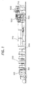
- FIG. 1 A preferred embodiment of a web offset printing press according to the present invention is shown in Fig. 1.
- the web offset printing press as shown in Fig. 1, continuously activates each device so that the previous job can be automatically switched to the next job.
- the web offset printing press comprises a sheet supply device 100, a plurality of printing units 200, a drying device 300, a cooling device, a web passing device 500, a drag device 600, a folding device 700, and so on.
- two web rolls 101 and 102 are attached to the both ends of a turret arm 104, respectively, and the turret arm 104 is pivotally mounted such that the arm 104 is rotatable about a central axis 103.
- a web 10 printing sheet
- a web from the next web roll 102 is jointed and supplied to the printing units 200.
- blanket cylinders 201, 202 and printing cylinders 203, 204 are arranged symmetrically with respect to a horizontal web traveling path.
- a blanket cleaning device 205 (206) is provided at each blanket cylinder 201 (202) and an automatic printing plate changer (APC) 202 (208) is provided at the printing cylinder 203 (204).
- the upper automatic printing plate changer 207 provides a guide frame 211 rotatable about a supporting axis 209, and an actuation 213 shifts the guide frame 211 from a stand by position to a printing plate changing position as shown in a dotted line.
- a holder 215 for holding an old printing plate or a new printing plate is provided.
- the old printing plate is released from the printing cylinder 203.
- the old printing plate is guided along the guide frame 211 so that the old printing plate can be picked up by extending/shrinking an actuator (not shown).
- the new printing plate is supplied to a printing cylinder 203 along the guide frame 211.
- the new printing plate is attached to the printing cylinder 203.
- a lower automatic printing plate changing device 208 provides a guide frame 212 rotatable about a supporting axis 210, and an actuator 214 shifts the guide frame 212 from a stand by position to a printing plate changing position along a dotted line as shown in the drawing.
- a holder 216 for holding the old printing plate or the new printing plate is provided at the guide frame 212.
- the old printing plate is disengaged from the printing cylinder 204.
- the old printing plate is lowered along the guide frame 211.
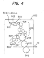
- an ink supplement device 800 is provided as shown in Fig. 4.
- the ink supply device 800 supplies ink 802 in an ink fountain 801 on an ink fountain roller 803 by adjusting an open degree of each ink fountains keys 804-1, 801-2, ... 801-n.
- Ink supplied on the ink fountain roller 803 is transferred to a printing plate 807 through a group 806 of ink rollers by operating an ink ductor roller 805. Simultaneously with such an ink supply operation, dampening water 808 is supplied to the printing plate 807 through a group of dampening rollers 809.
- the ink supply device 800 when changing the old printing plate 807 to a new printing plate, printing data such as an open degree of the each ink fountain keys 804-1, 804-2, ... 804-n corresponding to a picture pattern of the new printing plate, a rotational amount of the ink fountain roller 803, and a supply amount of dampening water in the dampening water tank 808 is preset as described below.
- the blanket cleaning device 205 (206) removes foreign matter such as remained ink and so on by contacting a brush or cloth with the blanket cylinder 201 (202).
- a drying machine 300 is a device for heating and drying a printed web 10 fed through the printing units 200.
- a cooling device 400 is a device for cooling the web 10 passed through the drying machine 300.
- a web path device 500 is a device for adjusting a passing direction to control a position of a web and its tensile force.
- a folding device 700 is a device for cutting the web after dry and cool operations and folds each piece of the web 10.
- folding devices based on combinations of cutting and folding the web, such as folding along a central line of the web with respect to a width direction, it is so-called as “former fold”, cutting a web having a predetermined length by a cut-off cylinder, folding a cut-off sheet by a folding cylinder along a width direction or a longitudinal direction, it is so called as “parallel fold”, and half folding parallel folded sheets by a chopper along an orthogonal direction.
- An infeed dancer device 150 is provided between the sheet supply device 100 and the printing units 200, and a final unit dancer device 250 is provided between the printing units 200 and the drying machine 300.
- the dancer device 150(250) winds a web among three rollers, and by moving a central roller in a vertical direction, removes slackness in the web caused by rotation of the printing units 200 in forward/backward directions.
- These devices 200 through 700 are connected by on driving axis and driven by a main motor (not shown) mounted at the printing units 200.
- the main motor can be disconnected from the driving axis by operating a driving clutch provided between the printing units 200 and the final unit dancer 250.
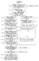
- the offset rotary printing press constructed as described above, is provided with a control device for simultaneously conducting the printing plate change and the folding device status change in accordance with a flow-chart as shown in Fig. 5 by an operator's turning on of a start button for changing a printing plate and a folding device status upon changing a printing job.
- step V1 when the switch for changing a printing plate and a folding device status is turned on, the rotary printing press is activated (step V1) and the driving clutch is turned off when the folding cylinder of the folding machine 700 has moved to a specific position (step V2).
- the reason for turning of the driving clutch is to avoid occurrence troubles in the folding machine 700, such as the folded sheet falling from the gripping cylinder and the folding cylinder, caused by the reverse rotation in the folding machine 700 for cutting and folding the folded sheet.
- step V3 the final unit dancer 250 is turned on (step V3) so that a web fed from the printing units 200 to the drying device 300 is prevented from becoming loose by winding the web around a roller moving in a up-down directions.
- step V4 when the plate cylinder 203 (204) is moved to a specific position for exchanging the printing plate, the device (the printing units 200 only) is stopped (step V4).
- the plate cylinders 203 (204) is rotated in the reverse direction, the old printing plate is removed from the plate cylinder 203 (204) by the automatic printing plate exchanger 207 (208) (step V5).
- step V6 By rotating the plate cylinder 203 (204) in a reverse direction, a roller of the finial unit dancer 250 is returned to the original position (step V6). At the same time, the infeed dancer device 150 is turned on (step V7) in order to avoid the web fed from the printing units 200 to the sheet supply device 100 from loosening.
- the machine (the printing units 200 only) is rotated in the forward direction, the new printing plate is supplied from the automatic printing plate exchanger 207 (208) and attached to the plate cylinder 203 (203) (step V9).
- step V10 the final unit dancer 250 is turned on (step V10) to prevent the web fed from the printing units 200 to the drying machine 300 from becoming loose. Simultaneously, the roller of the infeed dancer device 150 is returned to the original position (step V11).
- step V12 When setting of the new printing plate on the plate cylinder 203 (204) has completed, the machine (the printing units 200 only) is stopped (step V12).
- a brake of the folding machine is turned on (step V13) to change folding device status simultaneously.
- the folding device status is changed by adjusting a phase of the folding cylinder and the gripping cylinder (step V14) and a selection of a cam/guide member (step V15).
- An adjustment of the phase of the folding cylinder and the gripping cylinder means to change the phase of a gripping board of the gripping cylinder with respect to a needle and a knife of the folding cylinder corresponding to a single parallel fold or a double parallel fold.
- the adjustment is made by a gear transmission mechanism.
- Switching of the cam/guide member includes cam switching for changing a phase of a cam mechanism for switching an operation timing of a gripping claw, knife, needle and so on provided at a cutting cylinder, a folding cylinder and a gripping cylinder and a guide switching mechanism for changing the single parallel fold, the double parallel fold, and a delta fold.
- a cam switching mechanism comprises a cam holder 3 rotatably supported and having, on an outer peripheral portion thereof, protrusions 3a, 3b, a circular cam 4 attached to the cam holder 3 and having a predetermined outer peripheral shape, a cam follower 15 that rolls on the outer peripheral surface of the cam 4, a link plate 8 connected to the protrusion 3b of the cam holder 3 and extends and retreats to rotate the cam holder 3, a lever 10, an air cylinder 13, a first stopper 6 for restricting rotation of the cam 4 in one rotating direction caused by the extension the air cylinder 13, a second stopper 14 for restricting rotation of the cam 4 in the opposite rotating direction caused by retraction the air cylinder 13, and a third stopper 5 for urging the protrusion 3a of the cam holder 3, restricted from rotating in the opposite direction by the second stopper 14, in the rotating direction restricted by the second stopper 14.
- the detailed description of the above structure is described in Japanese Patent Publication No. 2000-130538 published on May 12, 2000 based on Japanese
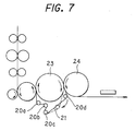
- the device as shown in Fig. 7, is a parallel folding device having a first gripping cylinder 23 and a second gripping cylinder 24, the peripheral surfaces of which are in contact with each other.
- a belt 21 is wound on the first gripping cylinder 23 and rollers 20a through 20d arranged parallel to the first gripping cylinder 23.
- the roller 20d is moved along a solid line in Fig. 7 and the belt 21 is moved to a guiding position.
- a sheet is changed from the first gripping cylinder 23 to the second gripping cylinder 24 to parallel-fold the sheet once.
- the roller 20d is moved toward an arrow along a dotted line in Fig. 7 and the belt 21 is shifted to a shelter position.
- the double parallel fold or the delta fold is operated when the sheet is passed from the first gripping cylinder 23 to the second gripping cylinder 24.
- step V16 Upon finishing the above exchange of the printing plates and the selection of folding device status, the driving clutch is turned on (step V16), and the dancer device 150, 250 is returned to the original position (step V17).
- each devices 100 through 800 are automatically operated by an operator's pushing of one button so that the total operation time can be shortened and the operator's task/burden becomes lighter.
- an automatic printing plate changing and a folding device status switching can be operated.
- the automatic printing plate changing and the folding device status switching are operated in parallel so that the total operation time can be shortened.
- the dancer devices 150, 250 wind up the web 10 among three rollers to prevent the web 10 from becoming loose at a portion between the sheet supplement device 100, the printing units 200, and the drying machine 300.
- the previous job is automatically changed to the new job by pushing one button.
- the automatic printing plate changing and the folding device status switching are simultaneously operated so that the total operation time can be shortened.
- the web In the operation for changing printing plates, even if the web is rotated in forward/backward directions, the web can be wound such that the web does not become loose at a portion between adjacent devices.
Landscapes
- Engineering & Computer Science (AREA)
- Mechanical Engineering (AREA)
- Folding Of Thin Sheet-Like Materials, Special Discharging Devices, And Others (AREA)
- Supply, Installation And Extraction Of Printed Sheets Or Plates (AREA)
- Inking, Control Or Cleaning Of Printing Machines (AREA)
Abstract
Description
Then, the new printing plate is supplied to a
Regarding the printing plate mounted on the printing cylinder 203 (204), an
Claims (6)
- A control device for controlling an automatic printing plate changing means (207, 208) and a folding device status switching means, comprising:printing plate changing means (207, 208) for changing a printing plate supported on a plate cylinder (203, 204); andfolding device status switching means for switching folding device status of a folding machine (700) in accordance with a folding device status corresponding to the next printing job,wherein said control device activates said printing plate changing means (207, 208) and said folding device status switching means simultaneously.
- A control device as claimed in claim 1, wherein said printing plate changing means (207, 208) intermits printing units when said plate cylinder (203, 204) is moved at a specific position for changing said printing plate, and rotates said plate cylinder in a reverse direction to pick up an old printing plate (101) from said plate cylinder and rotates said plate cylinder in a forward direction to set said new printing plate (102) to said plate cylinder.
- A control device as claimed in claim 1, wherein said folding device status switching means changes a phase of a gripping board of a gripping cylinder with respect to a needle and a knife of a folding cylinder in accordance with a single parallel fold and a double parallel fold.
- A control device as claimed in claim 1, wherein said folding device status switching means includes,a cam switch member for switching a phase of a cam mechanism for switching an operation timing of a cutting cylinder, a folding cylinder, and a gripping cylinder with operation tools such as a needle member and a knife member, anda guide switch member for switching a guide mechanism for selecting one of said single parallel fold, said double parallel fold, and said delta folding.
- A control device for controlling an automatic printing plate changing means and a folding device status switching means as claimed in claim 1, wherein said control device includes means for intermitting a travel of a web in said folding machine while said plate cylinder is rotated in forward and reverse directions to change from an old printing plate supported on said plate cylinder to a new printing plate.
- A cam switching mechanism, comprising:a cam holder having protrusions supported on an outer peripheral portion of said cam holder;a circular cam having a predetermined outer peripheral shape attached to said cam holder;a cam follower rolled on said outer peripheral surface of said circular cam;a link plate connected to said protrusion of the cam holder;a first stopper for restricting rotation of said circular cam in one direction caused by extending an air cylinder;a second stopper for restricting rotation of said circular cam in an opposite direction by contracting said air cylinder; anda third stopper for urging said protrusion of said circular cam holder restricted by the second stopper.
Applications Claiming Priority (2)
| Application Number | Priority Date | Filing Date | Title |
|---|---|---|---|
| JP2000144892 | 2000-05-17 | ||
| JP2000144892A JP2001322247A (en) | 2000-05-17 | 2000-05-17 | Control device for automatic plate changing device and folding specification switching device |
Publications (3)
| Publication Number | Publication Date |
|---|---|
| EP1155858A2 true EP1155858A2 (en) | 2001-11-21 |
| EP1155858A3 EP1155858A3 (en) | 2002-03-06 |
| EP1155858B1 EP1155858B1 (en) | 2007-06-27 |
Family
ID=18651478
Family Applications (1)
| Application Number | Title | Priority Date | Filing Date |
|---|---|---|---|
| EP01111906A Expired - Lifetime EP1155858B1 (en) | 2000-05-17 | 2001-05-17 | Device for controlling automatic printing plate changing means and folding device status switching device |
Country Status (5)
| Country | Link |
|---|---|
| EP (1) | EP1155858B1 (en) |
| JP (1) | JP2001322247A (en) |
| AT (1) | ATE365634T1 (en) |
| DE (1) | DE60129074T2 (en) |
| ES (1) | ES2286057T3 (en) |
Cited By (11)
| Publication number | Priority date | Publication date | Assignee | Title |
|---|---|---|---|---|
| DE102010042111A1 (en) | 2010-10-07 | 2012-04-12 | Koenig & Bauer Aktiengesellschaft | Printing plate i.e. panorama printing plate, changing system for printing unit of offset printing devices in logistic system in e.g. newspaper press, has guiding system with two guiding branches guided to plate cylinders of printing devices |
| DE102010042100A1 (en) | 2010-10-07 | 2012-04-12 | Koenig & Bauer Aktiengesellschaft | Transportation system for pressure unit in printing machine e.g. web-fed printing press, has drive unit that drives transfer unit along cylindrical-shaped transport path surrounding transfer position |
| DE102010042117A1 (en) | 2010-10-07 | 2012-04-12 | Koenig & Bauer Aktiengesellschaft | Printing plate changing system of printing system, has transfer unit that applies printing plate on attachment element after absorption by transfer unit and prior to winding on cylinder |
| WO2012045494A1 (en) | 2010-10-07 | 2012-04-12 | Koenig & Bauer Aktiengesellschaft | Transport system and printing-forme changing system in a press unit, and logistics system in a printing works |
| WO2012045493A1 (en) | 2010-10-07 | 2012-04-12 | Koenig & Bauer Aktiengesellschaft | Printing-forme carrier for a plurality of printing formes, storage device and method for providing a plurality of printing formes which are to be applied newly in a press unit, and transport system in a printing works |
| DE102010042094A1 (en) | 2010-10-07 | 2012-04-12 | Koenig & Bauer Aktiengesellschaft | Carrier element, particularly transport element in transportation system of printing shop for manual or automatic transport of multiple printing plates, has transport path that lies on outside of printing unit |
| DE102010042114A1 (en) | 2010-10-07 | 2012-04-12 | Koenig & Bauer Aktiengesellschaft | Printing plate changing system for printing unit and logistic system, has molding cylinder that is formed side by side in axial direction with multiple printing plate |
| WO2012045495A1 (en) | 2010-10-07 | 2012-04-12 | Koenig & Bauer Aktiengesellschaft | Printing-forme changing system of a press unit, logistics system in a printing works and method for applying one or more printing formes to a forme cylinder of a press unit |
| DE102010042091A1 (en) | 2010-10-07 | 2012-04-12 | Koenig & Bauer Aktiengesellschaft | Storage device for storing printing forms attached to form cylinder in printing unit of e.g. newspaper machine, has holding members arranged at distance to each other in cross member longitudinal sides transverse to longitudinal direction |
| DE102012202533B3 (en) * | 2012-02-20 | 2013-06-20 | Koenig & Bauer Aktiengesellschaft | Method for providing set of printing sheets to printing unit in newspaper printing machine, involves transporting set of sheets to destination while retaining relative positions between printing sheets |
| CN118024732A (en) * | 2024-03-12 | 2024-05-14 | 吾优新材料科技(江苏)有限公司 | A replaceable stamping mold replacement device for decorative film processing and production |
Families Citing this family (3)
| Publication number | Priority date | Publication date | Assignee | Title |
|---|---|---|---|---|
| JP5255381B2 (en) * | 2007-09-20 | 2013-08-07 | 株式会社小森コーポレーション | Control device and control method for strip printing machine |
| JP2009202461A (en) * | 2008-02-28 | 2009-09-10 | Mitsubishi Heavy Ind Ltd | Plate exchange control apparatus, printing machine, plate replacement method and plate replacing computer program |
| DE102020209465B3 (en) | 2020-07-28 | 2021-07-15 | Heidelberger Druckmaschinen Aktiengesellschaft | Printing plate gripping system |
Family Cites Families (3)
| Publication number | Priority date | Publication date | Assignee | Title |
|---|---|---|---|---|
| JP3066614B2 (en) * | 1991-09-19 | 2000-07-17 | 株式会社小森コーポレーション | Automatic plate exchange / plate registration method and device |
| FR2726259B1 (en) * | 1994-10-27 | 1997-01-17 | Heidelberg Harris Sa | DEVICE FOR CHANGING THE MODE OF A BENDING CYLINDER |
| DE19616629A1 (en) * | 1995-08-23 | 1997-11-06 | Heidelberg Harris Sa | Device for changing operating mode on folding apparatus |
-
2000
- 2000-05-17 JP JP2000144892A patent/JP2001322247A/en active Pending
-
2001
- 2001-05-17 ES ES01111906T patent/ES2286057T3/en not_active Expired - Lifetime
- 2001-05-17 AT AT01111906T patent/ATE365634T1/en not_active IP Right Cessation
- 2001-05-17 DE DE60129074T patent/DE60129074T2/en not_active Expired - Lifetime
- 2001-05-17 EP EP01111906A patent/EP1155858B1/en not_active Expired - Lifetime
Cited By (14)
| Publication number | Priority date | Publication date | Assignee | Title |
|---|---|---|---|---|
| DE102010042114A1 (en) | 2010-10-07 | 2012-04-12 | Koenig & Bauer Aktiengesellschaft | Printing plate changing system for printing unit and logistic system, has molding cylinder that is formed side by side in axial direction with multiple printing plate |
| DE102010042117B4 (en) * | 2010-10-07 | 2015-05-28 | Koenig & Bauer Aktiengesellschaft | Printing plate changing system of a printing unit and method for applying one or more printing plates on a forme cylinder of the printing unit |
| DE102010042117A1 (en) | 2010-10-07 | 2012-04-12 | Koenig & Bauer Aktiengesellschaft | Printing plate changing system of printing system, has transfer unit that applies printing plate on attachment element after absorption by transfer unit and prior to winding on cylinder |
| WO2012045494A1 (en) | 2010-10-07 | 2012-04-12 | Koenig & Bauer Aktiengesellschaft | Transport system and printing-forme changing system in a press unit, and logistics system in a printing works |
| WO2012045493A1 (en) | 2010-10-07 | 2012-04-12 | Koenig & Bauer Aktiengesellschaft | Printing-forme carrier for a plurality of printing formes, storage device and method for providing a plurality of printing formes which are to be applied newly in a press unit, and transport system in a printing works |
| DE102010042094A1 (en) | 2010-10-07 | 2012-04-12 | Koenig & Bauer Aktiengesellschaft | Carrier element, particularly transport element in transportation system of printing shop for manual or automatic transport of multiple printing plates, has transport path that lies on outside of printing unit |
| DE102010042091A1 (en) | 2010-10-07 | 2012-04-12 | Koenig & Bauer Aktiengesellschaft | Storage device for storing printing forms attached to form cylinder in printing unit of e.g. newspaper machine, has holding members arranged at distance to each other in cross member longitudinal sides transverse to longitudinal direction |
| DE102010042111A1 (en) | 2010-10-07 | 2012-04-12 | Koenig & Bauer Aktiengesellschaft | Printing plate i.e. panorama printing plate, changing system for printing unit of offset printing devices in logistic system in e.g. newspaper press, has guiding system with two guiding branches guided to plate cylinders of printing devices |
| DE102010042100A1 (en) | 2010-10-07 | 2012-04-12 | Koenig & Bauer Aktiengesellschaft | Transportation system for pressure unit in printing machine e.g. web-fed printing press, has drive unit that drives transfer unit along cylindrical-shaped transport path surrounding transfer position |
| WO2012045495A1 (en) | 2010-10-07 | 2012-04-12 | Koenig & Bauer Aktiengesellschaft | Printing-forme changing system of a press unit, logistics system in a printing works and method for applying one or more printing formes to a forme cylinder of a press unit |
| DE102010042114B4 (en) * | 2010-10-07 | 2014-11-20 | Koenig & Bauer Aktiengesellschaft | Printing plate changing system of a printing unit and logistics system of a printing company comprising a printing plate changing system |
| DE102010042111B4 (en) * | 2010-10-07 | 2015-03-26 | Koenig & Bauer Aktiengesellschaft | Printing plate changing system of a printing unit and logistics system of a printing company comprising a printing plate changing system |
| DE102012202533B3 (en) * | 2012-02-20 | 2013-06-20 | Koenig & Bauer Aktiengesellschaft | Method for providing set of printing sheets to printing unit in newspaper printing machine, involves transporting set of sheets to destination while retaining relative positions between printing sheets |
| CN118024732A (en) * | 2024-03-12 | 2024-05-14 | 吾优新材料科技(江苏)有限公司 | A replaceable stamping mold replacement device for decorative film processing and production |
Also Published As
| Publication number | Publication date |
|---|---|
| EP1155858B1 (en) | 2007-06-27 |
| JP2001322247A (en) | 2001-11-20 |
| ATE365634T1 (en) | 2007-07-15 |
| EP1155858A3 (en) | 2002-03-06 |
| DE60129074T2 (en) | 2008-03-13 |
| DE60129074D1 (en) | 2007-08-09 |
| ES2286057T3 (en) | 2007-12-01 |
Similar Documents
| Publication | Publication Date | Title |
|---|---|---|
| EP1155858B1 (en) | Device for controlling automatic printing plate changing means and folding device status switching device | |
| US6691619B2 (en) | Apparatus for automating switching operations of a web offset printing press | |
| JP2848821B2 (en) | Roll paper rotary printing press | |
| JPH11129435A (en) | Printer having replaceable form cylinder mounted on carriage | |
| JPH0776063A (en) | Printing press having at least one replaceable cylinder, especially including plate cylinder, or replaceable pressplate | |
| EP1155857B1 (en) | Apparatus for semi-automating switching operations of web offset printing press | |
| JP5331603B2 (en) | Width register adjusting device and printing machine | |
| US5738015A (en) | Device for guiding a print carrier | |
| JPH0577399A (en) | Pressplate replacing device in rotary press | |
| US6655285B2 (en) | Method and device for controlling automatic printing plate changing means and folding device status switching device | |
| US5797325A (en) | Cylinder cleaning apparatus for printing press | |
| JPH0410424B2 (en) | ||
| JP4824134B2 (en) | Semi-automatic device for switching work of offset rotary press | |
| JP2009096201A (en) | Printing plate exchanging method and exchanging device in processing machine | |
| JP4610579B2 (en) | Automatic switching device for offset rotary press | |
| JP4376363B2 (en) | Printing device | |
| JP2007118251A (en) | Rotary press and its control method | |
| CN101378909B (en) | printing press | |
| JP3694551B2 (en) | Original roller of printing press and ink fountain cleaning method | |
| JP7022532B2 (en) | Plate tightening system and method and printing machine | |
| JPH0577400A (en) | Pressplate replacing method and device in rotary press | |
| WO2010038649A1 (en) | Printing machine | |
| JP2001315308A (en) | Plate changing device for rotary printing press | |
| JP2002145519A (en) | Folding machine | |
| JPH08118590A (en) | Offset rotary press |
Legal Events
| Date | Code | Title | Description |
|---|---|---|---|
| PUAI | Public reference made under article 153(3) epc to a published international application that has entered the european phase |
Free format text: ORIGINAL CODE: 0009012 |
|
| AK | Designated contracting states |
Kind code of ref document: A2 Designated state(s): AT BE CH CY DE DK ES FI FR GB GR IE IT LI LU MC NL PT SE TR |
|
| AX | Request for extension of the european patent |
Free format text: AL;LT;LV;MK;RO;SI |
|
| PUAL | Search report despatched |
Free format text: ORIGINAL CODE: 0009013 |
|
| AK | Designated contracting states |
Kind code of ref document: A3 Designated state(s): AT BE CH CY DE DK ES FI FR GB GR IE IT LI LU MC NL PT SE TR |
|
| AX | Request for extension of the european patent |
Free format text: AL;LT;LV;MK;RO;SI |
|
| RIC1 | Information provided on ipc code assigned before grant |
Free format text: 7B 41F 33/16 A, 7B 41F 33/00 B, 7B 41F 27/12 B, 7B 41F 13/54 B, 7B 65H 45/16 B |
|
| 17P | Request for examination filed |
Effective date: 20020430 |
|
| AKX | Designation fees paid |
Free format text: AT BE CH CY DE DK ES FI FR GB GR IE IT LI LU MC NL PT SE TR |
|
| GRAP | Despatch of communication of intention to grant a patent |
Free format text: ORIGINAL CODE: EPIDOSNIGR1 |
|
| GRAS | Grant fee paid |
Free format text: ORIGINAL CODE: EPIDOSNIGR3 |
|
| GRAA | (expected) grant |
Free format text: ORIGINAL CODE: 0009210 |
|
| AK | Designated contracting states |
Kind code of ref document: B1 Designated state(s): AT BE CH CY DE DK ES FI FR GB GR IE IT LI LU MC NL PT SE TR |
|
| REG | Reference to a national code |
Ref country code: GB Ref legal event code: FG4D |
|
| REG | Reference to a national code |
Ref country code: CH Ref legal event code: EP |
|
| REG | Reference to a national code |
Ref country code: IE Ref legal event code: FG4D |
|
| REF | Corresponds to: |
Ref document number: 60129074 Country of ref document: DE Date of ref document: 20070809 Kind code of ref document: P |
|
| ET | Fr: translation filed | ||
| REG | Reference to a national code |
Ref country code: CH Ref legal event code: NV Representative=s name: R. A. EGLI & CO. PATENTANWAELTE |
|
| REG | Reference to a national code |
Ref country code: SE Ref legal event code: TRGR |
|
| PG25 | Lapsed in a contracting state [announced via postgrant information from national office to epo] |
Ref country code: AT Free format text: LAPSE BECAUSE OF FAILURE TO SUBMIT A TRANSLATION OF THE DESCRIPTION OR TO PAY THE FEE WITHIN THE PRESCRIBED TIME-LIMIT Effective date: 20070627 |
|
| REG | Reference to a national code |
Ref country code: ES Ref legal event code: FG2A Ref document number: 2286057 Country of ref document: ES Kind code of ref document: T3 |
|
| PG25 | Lapsed in a contracting state [announced via postgrant information from national office to epo] |
Ref country code: BE Free format text: LAPSE BECAUSE OF FAILURE TO SUBMIT A TRANSLATION OF THE DESCRIPTION OR TO PAY THE FEE WITHIN THE PRESCRIBED TIME-LIMIT Effective date: 20070627 |
|
| PG25 | Lapsed in a contracting state [announced via postgrant information from national office to epo] |
Ref country code: PT Free format text: LAPSE BECAUSE OF FAILURE TO SUBMIT A TRANSLATION OF THE DESCRIPTION OR TO PAY THE FEE WITHIN THE PRESCRIBED TIME-LIMIT Effective date: 20071127 |
|
| PG25 | Lapsed in a contracting state [announced via postgrant information from national office to epo] |
Ref country code: DK Free format text: LAPSE BECAUSE OF FAILURE TO SUBMIT A TRANSLATION OF THE DESCRIPTION OR TO PAY THE FEE WITHIN THE PRESCRIBED TIME-LIMIT Effective date: 20070627 Ref country code: GR Free format text: LAPSE BECAUSE OF FAILURE TO SUBMIT A TRANSLATION OF THE DESCRIPTION OR TO PAY THE FEE WITHIN THE PRESCRIBED TIME-LIMIT Effective date: 20070928 |
|
| PLBE | No opposition filed within time limit |
Free format text: ORIGINAL CODE: 0009261 |
|
| STAA | Information on the status of an ep patent application or granted ep patent |
Free format text: STATUS: NO OPPOSITION FILED WITHIN TIME LIMIT |
|
| 26N | No opposition filed |
Effective date: 20080328 |
|
| PG25 | Lapsed in a contracting state [announced via postgrant information from national office to epo] |
Ref country code: MC Free format text: LAPSE BECAUSE OF NON-PAYMENT OF DUE FEES Effective date: 20080531 |
|
| PG25 | Lapsed in a contracting state [announced via postgrant information from national office to epo] |
Ref country code: FI Free format text: LAPSE BECAUSE OF FAILURE TO SUBMIT A TRANSLATION OF THE DESCRIPTION OR TO PAY THE FEE WITHIN THE PRESCRIBED TIME-LIMIT Effective date: 20070627 |
|
| PG25 | Lapsed in a contracting state [announced via postgrant information from national office to epo] |
Ref country code: IE Free format text: LAPSE BECAUSE OF NON-PAYMENT OF DUE FEES Effective date: 20080519 |
|
| PG25 | Lapsed in a contracting state [announced via postgrant information from national office to epo] |
Ref country code: CY Free format text: LAPSE BECAUSE OF FAILURE TO SUBMIT A TRANSLATION OF THE DESCRIPTION OR TO PAY THE FEE WITHIN THE PRESCRIBED TIME-LIMIT Effective date: 20070627 |
|
| PGFP | Annual fee paid to national office [announced via postgrant information from national office to epo] |
Ref country code: ES Payment date: 20090609 Year of fee payment: 9 Ref country code: NL Payment date: 20090517 Year of fee payment: 9 |
|
| PGFP | Annual fee paid to national office [announced via postgrant information from national office to epo] |
Ref country code: FR Payment date: 20090515 Year of fee payment: 9 Ref country code: IT Payment date: 20090519 Year of fee payment: 9 Ref country code: SE Payment date: 20090512 Year of fee payment: 9 |
|
| PGFP | Annual fee paid to national office [announced via postgrant information from national office to epo] |
Ref country code: CH Payment date: 20090513 Year of fee payment: 9 |
|
| PGFP | Annual fee paid to national office [announced via postgrant information from national office to epo] |
Ref country code: GB Payment date: 20090513 Year of fee payment: 9 |
|
| PG25 | Lapsed in a contracting state [announced via postgrant information from national office to epo] |
Ref country code: LU Free format text: LAPSE BECAUSE OF NON-PAYMENT OF DUE FEES Effective date: 20080517 |
|
| PG25 | Lapsed in a contracting state [announced via postgrant information from national office to epo] |
Ref country code: TR Free format text: LAPSE BECAUSE OF FAILURE TO SUBMIT A TRANSLATION OF THE DESCRIPTION OR TO PAY THE FEE WITHIN THE PRESCRIBED TIME-LIMIT Effective date: 20070627 |
|
| REG | Reference to a national code |
Ref country code: NL Ref legal event code: V1 Effective date: 20101201 |
|
| REG | Reference to a national code |
Ref country code: CH Ref legal event code: PL |
|
| GBPC | Gb: european patent ceased through non-payment of renewal fee |
Effective date: 20100517 |
|
| EUG | Se: european patent has lapsed | ||
| REG | Reference to a national code |
Ref country code: FR Ref legal event code: ST Effective date: 20110131 |
|
| PG25 | Lapsed in a contracting state [announced via postgrant information from national office to epo] |
Ref country code: CH Free format text: LAPSE BECAUSE OF NON-PAYMENT OF DUE FEES Effective date: 20100531 Ref country code: LI Free format text: LAPSE BECAUSE OF NON-PAYMENT OF DUE FEES Effective date: 20100531 |
|
| PG25 | Lapsed in a contracting state [announced via postgrant information from national office to epo] |
Ref country code: SE Free format text: LAPSE BECAUSE OF NON-PAYMENT OF DUE FEES Effective date: 20100518 Ref country code: IT Free format text: LAPSE BECAUSE OF NON-PAYMENT OF DUE FEES Effective date: 20100517 Ref country code: NL Free format text: LAPSE BECAUSE OF NON-PAYMENT OF DUE FEES Effective date: 20101201 |
|
| PG25 | Lapsed in a contracting state [announced via postgrant information from national office to epo] |
Ref country code: FR Free format text: LAPSE BECAUSE OF NON-PAYMENT OF DUE FEES Effective date: 20100531 |
|
| REG | Reference to a national code |
Ref country code: ES Ref legal event code: FD2A Effective date: 20110714 |
|
| PG25 | Lapsed in a contracting state [announced via postgrant information from national office to epo] |
Ref country code: GB Free format text: LAPSE BECAUSE OF NON-PAYMENT OF DUE FEES Effective date: 20100517 Ref country code: ES Free format text: LAPSE BECAUSE OF NON-PAYMENT OF DUE FEES Effective date: 20110704 |
|
| PG25 | Lapsed in a contracting state [announced via postgrant information from national office to epo] |
Ref country code: ES Free format text: LAPSE BECAUSE OF NON-PAYMENT OF DUE FEES Effective date: 20100518 |
|
| PGFP | Annual fee paid to national office [announced via postgrant information from national office to epo] |
Ref country code: DE Payment date: 20120510 Year of fee payment: 12 |
|
| PG25 | Lapsed in a contracting state [announced via postgrant information from national office to epo] |
Ref country code: DE Free format text: LAPSE BECAUSE OF NON-PAYMENT OF DUE FEES Effective date: 20131203 |
|
| REG | Reference to a national code |
Ref country code: DE Ref legal event code: R119 Ref document number: 60129074 Country of ref document: DE Effective date: 20131203 |