EP1155230B1 - Ejector pump - Google Patents
Ejector pump Download PDFInfo
- Publication number
- EP1155230B1 EP1155230B1 EP00976064A EP00976064A EP1155230B1 EP 1155230 B1 EP1155230 B1 EP 1155230B1 EP 00976064 A EP00976064 A EP 00976064A EP 00976064 A EP00976064 A EP 00976064A EP 1155230 B1 EP1155230 B1 EP 1155230B1
- Authority
- EP
- European Patent Office
- Prior art keywords
- mixing tube
- nozzle
- ejector pump
- pump according
- jet pump
- Prior art date
- Legal status (The legal status is an assumption and is not a legal conclusion. Google has not performed a legal analysis and makes no representation as to the accuracy of the status listed.)
- Expired - Lifetime
Links
Images
Classifications
-
- F—MECHANICAL ENGINEERING; LIGHTING; HEATING; WEAPONS; BLASTING
- F02—COMBUSTION ENGINES; HOT-GAS OR COMBUSTION-PRODUCT ENGINE PLANTS
- F02M—SUPPLYING COMBUSTION ENGINES IN GENERAL WITH COMBUSTIBLE MIXTURES OR CONSTITUENTS THEREOF
- F02M37/00—Apparatus or systems for feeding liquid fuel from storage containers to carburettors or fuel-injection apparatus; Arrangements for purifying liquid fuel specially adapted for, or arranged on, internal-combustion engines
- F02M37/02—Feeding by means of suction apparatus, e.g. by air flow through carburettors
- F02M37/025—Feeding by means of a liquid fuel-driven jet pump
Definitions
- the invention relates to a suction jet pump with a nozzle arranged in front of a mixing tube and with holding elements for aligning the nozzle relative to the mixing tube, wherein the nozzle and the mixing tube made of plastic by injection molding.
- Suction jet pumps of the above type are often used in fuel tanks of today's motor vehicles and are therefore known.
- the suction jet pumps are usually used for filling a baffle arranged in the fuel tank or in a multi-chamber tank for conveying fuel from one chamber into the other chamber.
- the mixing tube and the nozzle are manufactured in separate molds, for example by injection molding and then glued together.
- the holding elements are designed as webs fixed integrally with the nozzle and are based on the assembly of the suction jet pump on corresponding surfaces of the mixing tube.
- a suction jet pump with a nozzle and an angled mixing tube is known, wherein only a part of the mixing tube is aligned with the nozzle. This part of the mixing tube and the nozzle are integrally connected. The second part of the mixing tube is formed as a separate part in the swirl pot.
- the invention is based on the problem of designing a suction jet pump of the type mentioned so that it has a particularly high efficiency and is inexpensive to produce.
- the nozzle and the mixing tube are designed for production as a continuous component in a common mold, that the nozzle and the mixing tube are integrally connected by at least two holding elements, and the holding elements for lateral delimitation of in the lateral surface the mixing tube arranged suction openings are formed.
- the suction jet pump has a particularly high efficiency. Since all essential components of the suction jet pump according to the invention are made in one piece, a faulty assembly also does not lead to a reduction in their efficiency.
- the ejector pump can also be produced particularly cost-effective by their production in a single mold. Another advantage of this design is that the ejector according to the invention has a high stability and therefore holding forces in the fuel tank do not lead to a reduction in their efficiency.
- a simultaneous alignment and attachment of the invention provided for the promotion of fuel in a surge pot of a motor vehicle suction jet pump can be easily achieved if it has means for their tension in a arranged in a fuel tank of a motor vehicle conveyor unit or a swirl pot. This leads to a strong simplification of the assembly of the suction jet pump in the conveyor unit.
- Another advantage of this strained in the delivery unit suction jet pump is that the delivery unit is very compact and can be modularly assembled into a pre-assembled unit.
- connection of the suction jet pump according to the invention to a propellant conduit is structurally particularly simple if the nozzle has on its side facing away from the mixing tube a sealing flange and means for clamping with a correspondingly shaped propellant conduit.
- the sealing flange of the nozzle and the propellant line can be screwed together for example, for clamping or connected to each other by latching means.
- annular sealing surface for sealing the suction jet pump mounted in the delivery unit or in the swirl pot is arranged on the outside of the mixing tube.
- the suction jet pump according to the invention can be easily braced in an adjacent component, if locking means are arranged for attachment to the conveyor unit or to the swirl pot on the outside of the mixing tube.
- the latching means are structurally particularly simple according to another advantageous embodiment of the invention, when the latching means are designed as latching hooks.
- the manufacture of the suction jet pump according to the invention can be produced in a largely axially demoldable tool shape when the entire mixing tube is designed straight from the intake to its free end straight or conically widening.
- straight sections of the mixing tube and conical sections may alternate here.
- Suction openings for the suction of fuel could be arranged, for example, in the nozzle receiving end face of the mixing tube.
- the suction jet pump according to the invention is designed to be particularly compact when the holding elements are designed for the lateral delimitation of suction openings arranged in the lateral surface of the mixing tube.
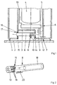
- FIG. 1 schematically shows a delivery unit 3 mounted in a swirl pot 1 of a fuel tank 2 of a motor vehicle.
- the delivery unit 3 has an impeller 5 of a feed pump 6 driven by an electric motor 4 and sealingly inserted into an opening 7 in the bottom of the swirl pot 1.
- a suction jet pump 8 is arranged in the holder for the conveyor unit 3.
- the suction jet pump 8 is supplied with fuel via a drive line 5 connected to the impeller 5.
- the pumped via the fuel line to the suction jet fuel first passes to a nozzle 10.
- the suction jet pump 8 sucks via suction 11 fuel from the fuel tank 1 and promotes this in the swirl pot 1.
- the feed pump 6 sucks from the swirl pot 1 fuel via a line 12th and promotes this via another line 13 to an internal combustion engine, not shown of the motor vehicle.
- the suction jet pump 8 has at its end near the nozzle 10 a sealing flange 14, with which it is biased against a correspondingly shaped region of the conveyor unit 3. With its end facing the sealing flange 14, the suction jet pump 8 penetrates a recess 15 of the conveyor unit 3. In the recess 15, an O-ring 16 is arranged.
- the suction jet pump 8 has an annular sealing surface 17 in this area.
- FIG 2 shows the suction jet pump 8 of Figure 1 in a perspective view.
- the suction jet pump has a mixing tube 18 facing the nozzle 10.
- the suction openings 11 are arranged in the mixing tube 18 in its region adjacent to the nozzle 10.
- the suction openings 11 are bounded laterally by retaining elements 19 designed as webs.
- the mixing tube 18 has a latching hook 20 attached to the outer circumferential surface.
- the radially outer and inner surfaces of the mixing tube 18 are each cylindrical.
- the nozzle 10 tapers toward the mixing tube 18.
- the suction jet pump 8 can be made in one piece with the exception of the suction openings 11 in an axially demoldable tool mold.
- the suction openings 11 can be made, for example, by means of cores to be introduced into the mold or by machining.
Description
Die Erfindung betrifft eine Saugstrahlpumpe mit einer vor einem Mischrohr angeordneten Düse und mit Halteelementen zur Ausrichtung der Düse gegenüber dem Mischrohr, wobei die Düse und das Mischrohr aus Kunststoff im Spritzgußverfahren gefertigt ist.The invention relates to a suction jet pump with a nozzle arranged in front of a mixing tube and with holding elements for aligning the nozzle relative to the mixing tube, wherein the nozzle and the mixing tube made of plastic by injection molding.
Saugstrahlpumpen der vorstehenden Art werden häufig in Kraftstoffbehältern heutiger Kraftfahrzeuge eingesetzt und sind daher bekannt. Die Saugstrahlpumpen werden meist zur Befüllung eines in dem Kraftstoffbehälter angeordneten Schwalltopfes oder bei einem Mehrkammertank zur Förderung von Kraftstoff aus der einen Kammer in die andere Kammer eingesetzt. Bei der Fertigung der bekannten Saugstrahlpumpe aus kraftstoffestem Kunststoff werden das Mischrohr und die Düse in getrennten Werkzeugformen beispielsweise im Spritzgußverfahren gefertigt und anschließend miteinander verklebt. Die Halteelemente sind dabei als einteilig mit der Düse befestigte Stege gestaltet und stützen sich nach der Montage der Saugstrahlpumpe an entsprechenden Flächen des Mischrohrs ab.Suction jet pumps of the above type are often used in fuel tanks of today's motor vehicles and are therefore known. The suction jet pumps are usually used for filling a baffle arranged in the fuel tank or in a multi-chamber tank for conveying fuel from one chamber into the other chamber. In the production of the known suction jet pump fuel-resistant plastic, the mixing tube and the nozzle are manufactured in separate molds, for example by injection molding and then glued together. The holding elements are designed as webs fixed integrally with the nozzle and are based on the assembly of the suction jet pump on corresponding surfaces of the mixing tube.
Nachteilig bei der bekannten Saugstrahlpumpe ist, daß die Düse und das Mischrohr jeweils Toleranzen aufweisen und daher nur sehr schwierig gegeneinander auszurichten sind. Eine fehlerhafte Ausrichtung der Düse gegenüber dem Mischrohr führt jedoch zu einem starken Absinken des Wirkungsgrades der Saugstrahlpumpe.A disadvantage of the known suction jet pump that the nozzle and the mixing tube each have tolerances and therefore are very difficult to align with each other. However, a faulty alignment of the nozzle relative to the mixing tube leads to a sharp decrease in the efficiency of the suction jet pump.
Aus der GB 2 271 327 ist eine Saugstrahlpumpe mit einer Düse und einem abgewinkelten Mischrohr bekannt, wobei lediglich ein Teil des Mischrohres zur Düse ausgerichtet ist. Dieser Teil des Mischrohres und die Düse sind einteilig miteinander verbunden. Der zweite Teil des Mischrohres ist als separates Teil im Schwalltopf angeformt.From
Der Erfindung liegt das Problem zugrunde, eine Saugstrahlpumpe der eingangs genannten Art so zu gestalten, daß sie einen besonders hohen Wirkungsgrad aufweist und kostengünstig herstellbar ist.The invention is based on the problem of designing a suction jet pump of the type mentioned so that it has a particularly high efficiency and is inexpensive to produce.
Dieses Problem wird erfindungsgemäß dadurch gelöst, daß die Düse und das Mischrohr zur Herstellung als zusammenhängendes Bauteil in einer gemeinsamen Werkzeugform gestaltet sind, daß die Düse und das Mischrohr durch mindestens zwei Halteelemente einteilig miteinander verbunden sind, und die Halteelemente zur seitlichen Begrenzung von in der Mantelfläche des Mischrohrs angeordneten Ansaugöffnungen ausgebildet sind.This problem is inventively solved in that the nozzle and the mixing tube are designed for production as a continuous component in a common mold, that the nozzle and the mixing tube are integrally connected by at least two holding elements, and the holding elements for lateral delimitation of in the lateral surface the mixing tube arranged suction openings are formed.
Durch diese Gestaltung sind die Düse und das Mischrohr nach ihrer Entnahme aus der Werkzeugform genau zueinander ausgerichtet. Hierdurch hat die Saugstrahlpumpe einen besonders hohen Wirkungsgrad. Da alle wesentlichen Bauteile der erfindungsgemäßen Saugstrahlpumpe einteilig gefertigt sind, führt eine fehlerhafte Montage ebenfalls nicht zu einer Verringerung ihres Wirkungsgrades. Die Saugstrahlpumpe läßt sich durch ihre Fertigung in einer einzigen Werkzeugform zudem besonders kostengünstig herstellen. Ein weiterer Vorteil dieser Gestaltung besteht darin, daß die erfindungsgemäße Saugstrahlpumpe eine hohe Stabilität aufweist und daher Haltekräfte im Kraftstoffbehälter nicht zu einer Verringerung ihres Wirkungsgrades führen.As a result of this configuration, the nozzle and the mixing tube are aligned exactly with one another after their removal from the mold. As a result, the suction jet pump has a particularly high efficiency. Since all essential components of the suction jet pump according to the invention are made in one piece, a faulty assembly also does not lead to a reduction in their efficiency. The ejector pump can also be produced particularly cost-effective by their production in a single mold. Another advantage of this design is that the ejector according to the invention has a high stability and therefore holding forces in the fuel tank do not lead to a reduction in their efficiency.
Eine gleichzeitige Ausrichtung und Befestigung der erfindungsgemäßen, zur Förderung von Kraftstoff in einen Schwalltopf eines Kraftfahrzeuges vorgesehenen Saugstrahlpumpe läßt sich einfach erreichen, wenn sie Mittel zu ihrer Verspannung in einer in einem Kraftstoffbehälter eines Kraftfahrzeuges angeordneten Fördereinheit oder einem Schwalltopf aufweist. Dies führt zu einer starken Vereinfachung der Montage der Saugstrahlpumpe in der Fördereinheit. Ein weiterer Vorteil dieser in der Fördereinheit verspannten Saugstrahlpumpe besteht darin, daß die Fördereinheit sehr kompakt aufgebaut ist und sich modulartig zu einer vormontierbaren Einheit zusammensetzen läßt.A simultaneous alignment and attachment of the invention provided for the promotion of fuel in a surge pot of a motor vehicle suction jet pump can be easily achieved if it has means for their tension in a arranged in a fuel tank of a motor vehicle conveyor unit or a swirl pot. This leads to a strong simplification of the assembly of the suction jet pump in the conveyor unit. Another advantage of this strained in the delivery unit suction jet pump is that the delivery unit is very compact and can be modularly assembled into a pre-assembled unit.
Der Anschluß der erfindungsgemäßen Saugstrahlpumpe an eine Treibmittelleitung gestaltet sich konstruktiv besonders einfach, wenn die Düse an ihrer dem Mischrohr abgewandten Seite einen Dichtflansch und Mittel zur Verspannung mit einer entsprechend gestalteten Treibmittelleitung aufweist. Der Dichtflansch der Düse und die Treibmittelleitung können zur Verspannung beispielsweise miteinander verschraubt oder durch Rastmittel miteinander verbunden sein.The connection of the suction jet pump according to the invention to a propellant conduit is structurally particularly simple if the nozzle has on its side facing away from the mixing tube a sealing flange and means for clamping with a correspondingly shaped propellant conduit. The sealing flange of the nozzle and the propellant line can be screwed together for example, for clamping or connected to each other by latching means.
Zur weiteren Vereinfachung der Montage der erfindungsgemäßen Saugstrahlpumpe trägt es bei, wenn an der Außenseite des Mischrohrs eine ringförmige Dichtfläche zur Abdichtung der in der Fördereinheit oder in dem Schwalltopf montierten Saugstrahlpumpe angeordnet ist.To further simplify the assembly of the suction jet pump according to the invention, it is helpful if an annular sealing surface for sealing the suction jet pump mounted in the delivery unit or in the swirl pot is arranged on the outside of the mixing tube.
Die erfindungsgemäße Saugstrahlpumpe läßt sich einfach in einem angrenzenden Bauteil verspannen, wenn an der Außenseite des Mischrohrs Rastmittel zur Befestigung an der Fördereinheit oder an dem Schwalltopf angeordnet sind.The suction jet pump according to the invention can be easily braced in an adjacent component, if locking means are arranged for attachment to the conveyor unit or to the swirl pot on the outside of the mixing tube.
Die Rastmittel gestalten sich gemäß einer anderen vorteilhaften Weiterbildung der Erfindung konstruktiv besonders einfach, wenn die Rastmittel als Rasthaken ausgebildet sind.The latching means are structurally particularly simple according to another advantageous embodiment of the invention, when the latching means are designed as latching hooks.
Die Fertigung der erfindungsgemäßen Saugstrahlpumpe läßt sich in einer größtenteils axial entformbaren Werkzeugform erzeugen, wenn das gesamte Mischrohr von dem Ansaugbereich bis zu seinem freien Ende hin gerade oder sich konisch erweiternd gestaltet ist. Selbstverständlich können sich hierbei gerade Abschnitte des Mischrohrs und konische Abschnitte abwechseln.The manufacture of the suction jet pump according to the invention can be produced in a largely axially demoldable tool shape when the entire mixing tube is designed straight from the intake to its free end straight or conically widening. Of course, straight sections of the mixing tube and conical sections may alternate here.
Ansaugöffnungen zur Ansaugung von Kraftstoff könnten beispielsweise in der die Düse aufnehmenden Stirnseite des Mischrohrs angeordnet sein. Die erfindungsgemäße Saugstrahlpumpe gestaltet sich jedoch besonders kompakt, wenn die Halteelemente zur seitlichen Begrenzung von in der Mantelfläche des Mischrohrs angeordneten Ansaugöffnungen ausgebildet sind.Suction openings for the suction of fuel could be arranged, for example, in the nozzle receiving end face of the mixing tube. However, the suction jet pump according to the invention is designed to be particularly compact when the holding elements are designed for the lateral delimitation of suction openings arranged in the lateral surface of the mixing tube.
Die Erfindung läßt zahlreiche Ausführungsformen zu. Zur weiteren Verdeutlichung ihres Grundprinzips ist eine davon in der Zeichnung dargestellt und wird nachfolgend beschrieben. Diese zeigt in
Figur 1- eine schematische Darstellung einer Fördereinheit mit einer erfindungsgemäßen Saugstrahlpumpe,
Figur 2- eine perspektivische Darstellung der Saugstrahlpumpe aus
Figur 1.
- FIG. 1
- a schematic representation of a conveyor unit with a suction jet pump according to the invention,
- FIG. 2
- a perspective view of the suction jet pump of Figure 1.
Figur 1 zeigt schematisch eine in einem Schwalltopf 1 eines Kraftstoffbehälters 2 eines Kraftfahrzeuges montierte Fördereinheit 3. Die Fördereinheit 3 hat ein von einem Elektromotor 4 angetriebenes Laufrad 5 einer Förderpumpe 6 und ist abdichtend in eine Öffnung 7 im Boden des Schwalltopfes 1 eingesetzt. Im Halter für die Fördereinheit 3 ist eine Saugstrahlpumpe 8 angeordnet. Die Saugstrahlpumpe 8 wird über eine mit dem Laufrad 5 verbundene Treibmittelleitung 9 mit Kraftstoff versorgt. Der über die Treibmittelleitung zu der Saugstrahlpumpe geförderte Kraftstoff gelangt zunächst zu einer Düse 10. Die Saugstrahlpumpe 8 saugt über Ansaugöffnungen 11 Kraftstoff aus dem Kraftstoffbehälter 1 an und fördert diesen in den Schwalltopf 1. Die Förderpumpe 6 saugt aus dem Schwalltopf 1 Kraftstoff über eine Leitung 12 an und fördert diesen über eine weitere Leitung 13 zu einer nicht dargestellten Brennkraftmaschine des Kraftfahrzeuges. Zur Verdeutlichung sind in der Zeichnung die Strömungen des Kraftstoffs mit Pfeilen gekennzeichnet. Die Saugstrahlpumpe 8 weist an ihrer der Düse 10 nahen Stirnseite einen Dichtflansch 14 auf, mit dem sie gegen einen entsprechend gestalteten Bereich der Fördereinheit 3 vorgespannt ist. Mit ihrem dem Dichtflansch 14 gegenüberstehenden Ende durchdringt die Saugstrahlpumpe 8 eine Ausnehmung 15 der Fördereinheit 3. In der Ausnehmung 15 ist ein O-Ring 16 angeordnet. Die Saugstrahlpumpe 8 weist in diesem Bereich eine ringförmige Dichtfläche 17 auf.FIG. 1 schematically shows a
Figur 2 zeigt die Saugstrahlpumpe 8 aus Figur 1 in einer perspektivischen Darstellung. Die Saugstrahlpumpe hat ein der Düse 10 gegenüberstehendes Mischrohr 18. Die Ansaugöffnungen 11 sind in dem Mischrohr 18 in dessen an die Düse 10 angrenzenden Bereich angeordnet. Die Ansaugöffnungen 11 werden seitlich von als Stegen ausgebildeten Halteelementen 19 begrenzt. Weiterhin hat das Mischrohr 18 einen an der Außenmantelfläche befestigten Rasthaken 20. Die radial äußere und die innere Fläche des Mischrohrs 18 sind jeweils zylindrisch gestaltet. Die Düse 10 verjüngt sich zu dem Mischrohr 18 hin. Hierdurch läßt sich die Saugstrahlpumpe 8 mit Ausnahme der Ansaugöffnungen 11 einteilig in einer axial entformbaren Werkzeugform fertigen. Die Ansaugöffnungen 11 lassen sich beispielsweise mittels in die Werkzeugform einzulegenden Kernen oder spanabhebend fertigen.Figure 2 shows the
Claims (7)
- Ejector pump (8) with a nozzle (10) arranged upstream of a mixing tube (18) and with holding elements (19) for aligning the nozzle (10) with respect to the mixing tube (18), the nozzle (10) and the mixing tube (18) being produced from plastic by the injection-moulding process, characterized in that the nozzle (10) and the mixing tube (18) are shaped in a common mould for production as an interconnected component, in that the nozzle (10) and the mixing tube (18) are integrally connected to one another by at least two holding elements (19), and in that the holding elements (19) are formed for lateral delimitation of intake openings (11) arranged in the lateral surface of the mixing tube (18).
- Ejector pump according to Claim 1, characterized in that it has means for bracing it in a delivery unit (3) or a surge chamber (1) arranged in a fuel tank (2) of a motor vehicle.
- Ejector pump according to Claim 1 or 2, characterized in that the nozzle (10) has on its side facing away from the mixing tube (18) a sealing flange (14) and means for bracing it with a correspondingly shaped fuel line (9).
- Ejector pump according to at least one of the preceding claims, characterized in that an annular sealing surface (17) is arranged on the outer side of the mixing tube (18) to seal off Ejector pump (8) fitted in the delivery unit (3) or in the surge chamber (1).
- Ejector pump according to at least one of the preceding claims, characterized in that snap-in means are arranged on the outer side of the mixing tube (18) for fastening on the delivery unit (3) or on the surge chamber (1).
- Ejector pump according to at least one of the preceding claims, characterized in that the snap-in means take the form of snap-in hooks (20).
- Ejector pump according to at least one of the preceding claims, characterized in that the entire mixing tube (18) is made straight or conically widening from the intake region to its free end.
Applications Claiming Priority (3)
| Application Number | Priority Date | Filing Date | Title |
|---|---|---|---|
| DE19957066 | 1999-11-26 | ||
| DE19957066A DE19957066A1 (en) | 1999-11-26 | 1999-11-26 | Siphon for supply unit in vehicle fuel tank, with jet and mixing tube made as mutually dependent components in common tool mold |
| PCT/EP2000/011607 WO2001038719A1 (en) | 1999-11-26 | 2000-11-22 | Ejector pump |
Publications (2)
| Publication Number | Publication Date |
|---|---|
| EP1155230A1 EP1155230A1 (en) | 2001-11-21 |
| EP1155230B1 true EP1155230B1 (en) | 2006-01-18 |
Family
ID=7930502
Family Applications (1)
| Application Number | Title | Priority Date | Filing Date |
|---|---|---|---|
| EP00976064A Expired - Lifetime EP1155230B1 (en) | 1999-11-26 | 2000-11-22 | Ejector pump |
Country Status (9)
| Country | Link |
|---|---|
| US (1) | US6619927B1 (en) |
| EP (1) | EP1155230B1 (en) |
| JP (1) | JP2003515046A (en) |
| KR (1) | KR20010101711A (en) |
| CN (1) | CN1338026A (en) |
| BR (1) | BR0007712B1 (en) |
| DE (2) | DE19957066A1 (en) |
| ES (1) | ES2256058T3 (en) |
| WO (1) | WO2001038719A1 (en) |
Families Citing this family (10)
| Publication number | Priority date | Publication date | Assignee | Title |
|---|---|---|---|---|
| DE10237050B3 (en) | 2002-08-09 | 2004-04-15 | Siemens Ag | eductor |
| ES2245567B1 (en) * | 2003-09-16 | 2007-04-01 | Loramendi, S.A. | BOX EXPULSION DEVICE DEVICE WITH DISTRIBUTION OF DEMOLDING AGENT. |
| KR100578540B1 (en) * | 2004-07-28 | 2006-05-15 | 한국뉴매틱(주) | Vacuum ejector pumps |
| US7914263B2 (en) * | 2007-05-14 | 2011-03-29 | Vladimir Berger | Ejector-type rotary device |
| US8644260B2 (en) * | 2009-05-01 | 2014-02-04 | Qualcomm Incorporated | Apparatus and method for increasing reliability of serving cell change |
| US9039385B2 (en) | 2011-11-28 | 2015-05-26 | Ford Global Technologies, Llc | Jet pump assembly |
| DE102013203942B4 (en) * | 2013-03-07 | 2014-12-04 | Continental Automotive Gmbh | In a fuel tank of a motor vehicle arranged suction jet pump |
| DE102016206616A1 (en) | 2016-04-19 | 2017-10-19 | Elringklinger Ag | Ejector device and combination of a cylinder head cover and an ejector device |
| DE102016206615A1 (en) * | 2016-04-19 | 2017-10-19 | Elringklinger Ag | Ejector device and combination of a cylinder head cover and an ejector device |
| DE102021202671A1 (en) * | 2021-03-18 | 2022-09-22 | Vitesco Technologies GmbH | Mixing tube blank, mixing tube, mixing tube holder, ejector pump and method for their manufacture |
Family Cites Families (18)
| Publication number | Priority date | Publication date | Assignee | Title |
|---|---|---|---|---|
| GB1530128A (en) * | 1974-10-21 | 1978-10-25 | Gen Electric | Jet pumps and nozzles therefor |
| US4834132A (en) * | 1986-09-25 | 1989-05-30 | Nissan Motor Company, Limited | Fuel transfer apparatus |
| DE3719809C1 (en) * | 1987-06-13 | 1988-06-09 | Daimler Benz Ag | Storage tank for fuel tanks |
| JP2580021B2 (en) * | 1988-12-07 | 1997-02-12 | 日産自動車株式会社 | Slewing tank for automotive fuel tank |
| DE8815751U1 (en) * | 1988-12-20 | 1989-02-16 | Gebr. Jordan Gmbh & Co Kg, 5860 Iserlohn, De | |
| WO1992008037A1 (en) * | 1990-11-03 | 1992-05-14 | Peco Machine Shop & Inspection Services Ltd. | Downhole jet pump system using gas as driving fluid |
| GB2271327A (en) * | 1992-10-10 | 1994-04-13 | Ford Motor Co | A fuel tank reservoir. |
| DE4310761C2 (en) * | 1993-04-01 | 1995-10-12 | Kayser A Gmbh & Co Kg | Jet pump |
| DE4400958C1 (en) * | 1994-01-14 | 1995-04-06 | Bayerische Motoren Werke Ag | Sucking jet pump |
| DE19512700A1 (en) * | 1995-04-07 | 1996-10-10 | Teves Gmbh Alfred | Jet pump |
| DE19530423C2 (en) * | 1995-08-18 | 1999-06-02 | Mannesmann Vdo Ag | Suction jet pump for use in a fuel tank |
| DE19618649A1 (en) * | 1996-05-09 | 1997-11-13 | Bosch Gmbh Robert | Fuel delivery device of a motor vehicle |
| DE19714858C1 (en) * | 1997-04-10 | 1998-11-19 | Kayser Automotive Systems Gmbh | Suction jet pump |
| DE19805072C2 (en) * | 1998-02-09 | 1999-11-11 | Bosch Gmbh Robert | Fuel delivery module |
| SE511716E5 (en) * | 1998-03-20 | 2009-01-28 | Piab Ab | ejector |
| DE19830504B4 (en) * | 1998-07-08 | 2005-12-22 | Siemens Ag | For use in a fuel tank of a motor vehicle provided swirl pot |
| DE19833130A1 (en) * | 1998-07-23 | 2000-01-27 | Bosch Gmbh Robert | Apparatus for conveying fuel from a storage container to an I.C. engine has an opening on a level above the base of a section to form a storage chamber |
| EP1103717B1 (en) * | 1999-11-23 | 2005-03-23 | Siemens Aktiengesellschaft | Pump unit disposed in a surge chamber of a fuel tank of a vehicle |
-
1999
- 1999-11-26 DE DE19957066A patent/DE19957066A1/en not_active Withdrawn
-
2000
- 2000-11-22 CN CN00803092A patent/CN1338026A/en active Pending
- 2000-11-22 US US09/890,034 patent/US6619927B1/en not_active Expired - Lifetime
- 2000-11-22 ES ES00976064T patent/ES2256058T3/en not_active Expired - Lifetime
- 2000-11-22 EP EP00976064A patent/EP1155230B1/en not_active Expired - Lifetime
- 2000-11-22 WO PCT/EP2000/011607 patent/WO2001038719A1/en active IP Right Grant
- 2000-11-22 DE DE50012089T patent/DE50012089D1/en not_active Expired - Lifetime
- 2000-11-22 JP JP2001540038A patent/JP2003515046A/en not_active Withdrawn
- 2000-11-22 KR KR1020017009396A patent/KR20010101711A/en not_active Application Discontinuation
- 2000-11-22 BR BRPI0007712-7A patent/BR0007712B1/en not_active IP Right Cessation
Also Published As
| Publication number | Publication date |
|---|---|
| DE19957066A1 (en) | 2001-05-31 |
| BR0007712A (en) | 2001-11-27 |
| CN1338026A (en) | 2002-02-27 |
| KR20010101711A (en) | 2001-11-14 |
| ES2256058T3 (en) | 2006-07-16 |
| US6619927B1 (en) | 2003-09-16 |
| DE50012089D1 (en) | 2006-04-06 |
| WO2001038719A1 (en) | 2001-05-31 |
| JP2003515046A (en) | 2003-04-22 |
| EP1155230A1 (en) | 2001-11-21 |
| BR0007712B1 (en) | 2010-04-06 |
Similar Documents
| Publication | Publication Date | Title |
|---|---|---|
| EP1301367B1 (en) | Fuel delivery unit | |
| EP1155230B1 (en) | Ejector pump | |
| EP1417110B1 (en) | Pump unit arranged in an inner tank of a fuel tank of a motor vehicle | |
| EP1103717B1 (en) | Pump unit disposed in a surge chamber of a fuel tank of a vehicle | |
| WO2007115925A1 (en) | Suction jet pump | |
| DE2401728C2 (en) | Round swirl pot arranged in the fuel tank of a motor vehicle | |
| DE102006003420B4 (en) | delivery unit | |
| WO2002020974A1 (en) | Filter module for a fuel conveying unit and fuel conveying unit for a motor vehicle | |
| DE4111341A1 (en) | Saddle-shaped vehicle fuel tank - has venturi pump to transfer fuel and two=stage main fuel pump with low pressure stage | |
| WO2008006833A1 (en) | Feed unit for feeding fuel | |
| DE102012221555A1 (en) | Filter top shell, filter and method for producing a filter top shell | |
| WO2003012280A1 (en) | Fuel transporting device for a motor vehicle | |
| DE3130286A1 (en) | Pump for delivering fuel from a storage tank to an internal-combustion engine | |
| EP1861625B1 (en) | Jet suction pump | |
| DE10055344A1 (en) | Conveying unit arranged in a swirl pot of a fuel tank of a motor vehicle | |
| DE102016212858B4 (en) | eductor | |
| EP1120572A2 (en) | Centrifugal pump | |
| EP2066518B1 (en) | Fuel delivery unit for a motor vehicle | |
| DE19534411A1 (en) | Fuel-pump mounting inside tank | |
| DE10322621B4 (en) | For attachment in a fuel tank provided delivery unit | |
| EP1022457A2 (en) | Fuel feed device | |
| DE19737885B4 (en) | Centrifugal pump for generating a water-air mixture | |
| EP1105649A1 (en) | Liquid pump, especially for delivering fuel | |
| EP1704321B1 (en) | Fuel conveying unit |
Legal Events
| Date | Code | Title | Description |
|---|---|---|---|
| PUAI | Public reference made under article 153(3) epc to a published international application that has entered the european phase |
Free format text: ORIGINAL CODE: 0009012 |
|
| 17P | Request for examination filed |
Effective date: 20010725 |
|
| AK | Designated contracting states |
Kind code of ref document: A1 Designated state(s): AT BE CH CY DE DK ES FI FR GB GR IE IT LI LU MC NL PT SE TR |
|
| RBV | Designated contracting states (corrected) |
Designated state(s): DE ES FR GB SE |
|
| 17Q | First examination report despatched |
Effective date: 20040728 |
|
| GRAP | Despatch of communication of intention to grant a patent |
Free format text: ORIGINAL CODE: EPIDOSNIGR1 |
|
| GRAS | Grant fee paid |
Free format text: ORIGINAL CODE: EPIDOSNIGR3 |
|
| GRAA | (expected) grant |
Free format text: ORIGINAL CODE: 0009210 |
|
| AK | Designated contracting states |
Kind code of ref document: B1 Designated state(s): DE ES FR GB SE |
|
| REG | Reference to a national code |
Ref country code: GB Ref legal event code: FG4D Free format text: NOT ENGLISH |
|
| REF | Corresponds to: |
Ref document number: 50012089 Country of ref document: DE Date of ref document: 20060406 Kind code of ref document: P |
|
| PG25 | Lapsed in a contracting state [announced via postgrant information from national office to epo] |
Ref country code: SE Free format text: LAPSE BECAUSE OF FAILURE TO SUBMIT A TRANSLATION OF THE DESCRIPTION OR TO PAY THE FEE WITHIN THE PRESCRIBED TIME-LIMIT Effective date: 20060418 |
|
| GBT | Gb: translation of ep patent filed (gb section 77(6)(a)/1977) |
Effective date: 20060411 |
|
| REG | Reference to a national code |
Ref country code: ES Ref legal event code: FG2A Ref document number: 2256058 Country of ref document: ES Kind code of ref document: T3 |
|
| ET | Fr: translation filed | ||
| PLBE | No opposition filed within time limit |
Free format text: ORIGINAL CODE: 0009261 |
|
| STAA | Information on the status of an ep patent application or granted ep patent |
Free format text: STATUS: NO OPPOSITION FILED WITHIN TIME LIMIT |
|
| 26N | No opposition filed |
Effective date: 20061019 |
|
| PGFP | Annual fee paid to national office [announced via postgrant information from national office to epo] |
Ref country code: ES Payment date: 20081121 Year of fee payment: 9 |
|
| PGFP | Annual fee paid to national office [announced via postgrant information from national office to epo] |
Ref country code: GB Payment date: 20081117 Year of fee payment: 9 |
|
| GBPC | Gb: european patent ceased through non-payment of renewal fee |
Effective date: 20091122 |
|
| PG25 | Lapsed in a contracting state [announced via postgrant information from national office to epo] |
Ref country code: GB Free format text: LAPSE BECAUSE OF NON-PAYMENT OF DUE FEES Effective date: 20091122 |
|
| REG | Reference to a national code |
Ref country code: ES Ref legal event code: FD2A Effective date: 20110407 |
|
| REG | Reference to a national code |
Ref country code: FR Ref legal event code: TP |
|
| PG25 | Lapsed in a contracting state [announced via postgrant information from national office to epo] |
Ref country code: ES Free format text: LAPSE BECAUSE OF NON-PAYMENT OF DUE FEES Effective date: 20110328 |
|
| PG25 | Lapsed in a contracting state [announced via postgrant information from national office to epo] |
Ref country code: ES Free format text: LAPSE BECAUSE OF NON-PAYMENT OF DUE FEES Effective date: 20091123 |
|
| PGFP | Annual fee paid to national office [announced via postgrant information from national office to epo] |
Ref country code: DE Payment date: 20141130 Year of fee payment: 15 Ref country code: FR Payment date: 20141119 Year of fee payment: 15 |
|
| REG | Reference to a national code |
Ref country code: DE Ref legal event code: R119 Ref document number: 50012089 Country of ref document: DE |
|
| REG | Reference to a national code |
Ref country code: FR Ref legal event code: ST Effective date: 20160729 |
|
| PG25 | Lapsed in a contracting state [announced via postgrant information from national office to epo] |
Ref country code: DE Free format text: LAPSE BECAUSE OF NON-PAYMENT OF DUE FEES Effective date: 20160601 |
|
| PG25 | Lapsed in a contracting state [announced via postgrant information from national office to epo] |
Ref country code: FR Free format text: LAPSE BECAUSE OF NON-PAYMENT OF DUE FEES Effective date: 20151130 |