EP1120572A2 - Centrifugal pump - Google Patents
Centrifugal pump Download PDFInfo
- Publication number
- EP1120572A2 EP1120572A2 EP00121080A EP00121080A EP1120572A2 EP 1120572 A2 EP1120572 A2 EP 1120572A2 EP 00121080 A EP00121080 A EP 00121080A EP 00121080 A EP00121080 A EP 00121080A EP 1120572 A2 EP1120572 A2 EP 1120572A2
- Authority
- EP
- European Patent Office
- Prior art keywords
- spur
- pump
- housing part
- centrifugal pump
- peripheral wall
- Prior art date
- Legal status (The legal status is an assumption and is not a legal conclusion. Google has not performed a legal analysis and makes no representation as to the accuracy of the status listed.)
- Withdrawn
Links
Images


Classifications
-
- F—MECHANICAL ENGINEERING; LIGHTING; HEATING; WEAPONS; BLASTING
- F04—POSITIVE - DISPLACEMENT MACHINES FOR LIQUIDS; PUMPS FOR LIQUIDS OR ELASTIC FLUIDS
- F04D—NON-POSITIVE-DISPLACEMENT PUMPS
- F04D29/00—Details, component parts, or accessories
- F04D29/40—Casings; Connections of working fluid
- F04D29/42—Casings; Connections of working fluid for radial or helico-centrifugal pumps
- F04D29/426—Casings; Connections of working fluid for radial or helico-centrifugal pumps especially adapted for liquid pumps
- F04D29/428—Discharge tongues
Definitions
- the invention relates to a centrifugal pump with a processable from injection molding Plastic material existing multi-part pump housing, the first housing part with an axially formed suction nozzle and one approximately tangential to one Is molded in one piece and has a sealing edge, over which it is sealed with a second housing part receiving an electric motor is connected, the pump housing having a substantially cylindrical includes pump chamber through which the medium can flow, the inner contour of which is spiral and in which a pump wheel driven by the electric motor is rotatably arranged.
- the object of the present invention is therefore in a centrifugal pump Generic type to create an economical manufacturing possibility while doing so to achieve a very good efficiency.
- the curvature of the inner contour of the Spur constantly from the curvature of the inner contour of the peripheral wall to the curvature the inner contour of the discharge nozzle and the inner contour of the spur to form as part of the spiral inner contour of the peripheral wall.
- the peripheral wall of the pump chamber is cylindrical in order to Injection molding process can be easily manufactured without an undercut. Your here The resulting rectangular cross-section in the area of the pressure port goes continuously and harmoniously into the circular shape of the mentioned pressure port.
- the spur in the area of Pressure port essentially semi-cylindrical and on the opposite side to be tapered. This largely avoids turbulence thus increasing the efficiency.
- the tapered contour does not meet the strength requirements. It is therefore provided that the spur is semi-cylindrical and in the area of the pressure port the opposite side to one that ensures sufficient stability Forming material thickness to taper.
- the contour of the spur is part of a spiral channel on the inside. With that she leaves from the cylindrical wall of the spiral channel to the approximately semi-cylindrical trained rounding over. Its outer contour lies on the wall of the pump head and the entire spur is designed in such a way that it fits into the Inserts the wall of the pump head without affecting its strength.
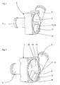
- Fig. 1 shows the first housing part 3 of a known centrifugal pump, consisting of a axially formed suction nozzle 5, an approximately tangentially molded pressure nozzle 6 and a substantially cylindrical, radially delimited by the wall 14 spiral pump chamber 9.
- the transition region 13 between the wall 14 and the pressure port 6 is formed by a sharp edge 15. This edge 15 affects unfavorable on the efficiency of the pump, because at this point the laminar Flow is disturbed and the flow resistance increases significantly.
- Fig. 2 shows a spatial representation of a fluid mechanically more favorable solution for the first housing part 3, consisting of an axially molded suction nozzle 5, a Pressure port 6 and a substantially cylindrical, radially through a Circumferential wall 14 delimited spiral pump chamber 9.
- a transition area 13 forms a spur 12 between the peripheral wall 14 and the pressure port 6 a round contour 11.
- the spur 12 is shaped that its curvature continuously from the peripheral wall 14 to an inner contour 20 of the Pressure port 6 passes. Because of the tongue that tapers here of a tool positive is the shorter tool life a production of this housing part 3 is uneconomical.
- the spur 12 is in the Transition area between the narrowest and the widest point of the spiral Gap between a pump wheel 8 and the inner contour 20 of the Circumferential wall 14 arranged.
- FIG. 3 shows a second housing part 4, which can be produced by injection molding Centrifugal pump according to the invention, which is functionally similar to the centrifugal pump from FIG. 2.
- the second housing part 4 is in one piece with a spur 12 which has a curve 11. Furthermore, the second housing part has a sealing edge 7 and a rotor space 18, wherein the rotor space 18 is delimited by a can 16, which in the air gap between a rotor and a stator (not shown) of an electric motor 10 is arranged.
- the solution shown is applicable to both internal rotor and external rotor motors.
- Fig. 4 shows a first housing part 3 of the centrifugal pump according to the invention
- the one with the second housing part 4 one-piece spur 12 is in a transition region 13 between a peripheral wall 14 and a pressure nozzle 6 shown arranged; it hugs the inside of the Circumferential wall 14.
- Fig. 5 shows the centrifugal pump according to the invention with the pump housing 2, consisting from the first housing part 3 with the pressure port 6 and the second housing part 4 with the spur 12 and a built-in impeller 8.
- Fig. 6 shows an overall view of the centrifugal pump according to the invention, with the Pump housing 2, consisting of the first housing part 3 with the pressure port 6, the Suction nozzle 5 and the second housing part 4, which contains the electric motor 10, the second housing part 4 consisting essentially of the rotor space and one Recording space for the electric motor 10, the second housing part 4 one-piece can 16 the rotor space from the receiving space for the electric motor 10 separates.
- the two housing parts 3, 4 are outside of their sealing edge Fastening recesses 22 for receiving fasteners (not shown).
- the rotor of the electric motor 10 is a permanent magnet rotor and the rotor chamber 18 is at least in proper operation with the pumped product Medium filled.
- the centrifugal pump 1 is a swirl pump, the scope of the invention is not limited to the example shown. It is among other things also possible that the Suction nozzle 5 is angled.
- Fig. 7 shows the first housing part 3 of the centrifugal pump according to the invention, with the Pressure port 6, mounting recesses 22, the peripheral wall 14, the spur 12, a receptacle 21 for mounting the pump wheel 8 and the sealing edge 7.
- Housing part 3 is the one-piece with the housing part 4 spur 12, as in assembled state arranged, shown.
- the continuation is clearly visible the spiral-shaped inner contour 20 of the peripheral wall 14 through the inner contour 19 of the Spurs 12.
- a rounding 23 which prevents a Notch effect is provided in the housing part 3. You can clearly see the development of the Spiral, starting in the area of spur 12.
Abstract
Die Erfindung betrifft eine Kreiselpumpe, mit einem aus spritzgusstechnisch verarbeitbarem Kunststoffmaterial bestehenden zumindest zweiteiligen Pumpengehäuse (2), dessen erstes Gehäuseteil (3) mit einem axial angeformten Saugstutzen (5) und einem in etwa tangential an einer Umfangswandung (14) angeformten Druckstutzen (6) einstückig ist und einen Dichtrand (7) aufweist, über den es dicht mit einem zweiten , einen Eletromotor (10) aufnehmenden Gehäuseteil (4) verbunden ist, wobei das Pumpengehäuse (2) einen im wesentlichen zylindrischen fördermitteldurchströmbaren Pumpenraum (9) einschließt, in welchem ein vom Elektromotor angetriebenes Pumpenrad drehbar angeordnet ist. Bei einer bekannten Kreiselpumpe der gattungsgemäßen Art ist der Übergang zwischen der Pumpenkammer und dem Druckstutzen aus fertigungstechnischen Gründen kantig ausgebildet. Dadurch entstehen Wirbel, die den Wirkungsgrad der Pumpe erheblich herabsetzen. Aufgabe der vorliegenden Erfindung ist es bei einer Kreiselpumpe der gattungsgemäßen Art eine wirtschaftliche Fertigungsmöglichkeit zu schaffen und dabei einen sehr guten Wirkungsgrad zu erreichen. Diese Aufgabe wird erfindungsgemäß dadurch gelöst, dass innerhalb des durch die beiden Gehäuseteile (3,4) begrenzten Pumpenraumes (9) ein mit einer Rundung (11) versehener Sporn (12) einstückig mit dem zweiten Gehäuseteil derart ausgebildet und im Pumpenraum angeordnet ist, dass er im Übergangsbereich zwischen dem Druckstutzen (6) und dem Pumpenraum (9) am ersten Gehäuseteil einen stetigen und stufenlosen Übergang von der den Pumpenraum begrenzenden Umfangswandung über den Sporn (12) zum Druckstutzen (6) bildet. <IMAGE>The invention relates to a centrifugal pump with an at least two-part pump housing (2) made of plastic material that can be processed by injection molding, the first housing part (3) of which has an axially molded suction nozzle (5) and a pressure nozzle (6) formed approximately tangentially on a peripheral wall (14). is in one piece and has a sealing edge (7) via which it is tightly connected to a second housing part (4) accommodating an electric motor (10), the pump housing (2) including an essentially cylindrical pump chamber (9) through which conveyable medium can flow, in which a pump wheel driven by the electric motor is rotatably arranged. In a known centrifugal pump of the generic type, the transition between the pump chamber and the pressure port is angular for manufacturing reasons. This creates vortices that significantly reduce the efficiency of the pump. The object of the present invention is to provide an economical production possibility in a centrifugal pump of the generic type and to achieve a very good efficiency. This object is achieved according to the invention in that within the pump chamber (9) delimited by the two housing parts (3, 4), a spur (12) provided with a curve (11) is formed in one piece with the second housing part and arranged in the pump chamber in such a way that it forms a steady and stepless transition from the peripheral wall delimiting the pump chamber via the spur (12) to the pressure nozzle (6) in the transition area between the pressure nozzle (6) and the pump chamber (9) on the first housing part. <IMAGE>
Description
Die Erfindung betrifft eine Kreiselpumpe, mit einem aus spritzgusstechnisch verarbeitbarem Kunststoffmaterial bestehenden mehrteiligen Pumpengehäuse, dessen erstes Gehäuseteil mit einem axial angeformten Saugstutzen und einem in etwa tangential an einer Umfangswandung angeformten Druckstutzen einstückig ist und einen Dichtrand aufweist, über den es dicht mit einem zweiten, einen Elektromotor aufnehmenden Gehäuseteil verbunden ist, wobei das Pumpengehäuse einen im wesentlichen zylindrischen fördermediumdurchströmbaren Pumpenraum einschließt, dessen Innenkontur spiralförmig ist und in welchem ein vom Elektromotor angetriebenes Pumpenrad drehbar angeordnet ist.The invention relates to a centrifugal pump with a processable from injection molding Plastic material existing multi-part pump housing, the first housing part with an axially formed suction nozzle and one approximately tangential to one Is molded in one piece and has a sealing edge, over which it is sealed with a second housing part receiving an electric motor is connected, the pump housing having a substantially cylindrical includes pump chamber through which the medium can flow, the inner contour of which is spiral and in which a pump wheel driven by the electric motor is rotatably arranged.
Bei einer bekannten Kreiselpumpe der gattungsgemäßen Art ist der Übergang zwischen der Pumpenkammer und dem Druckstutzen kantig ausgebildet. Diese Kante verursacht Wirbel in der Stömung, die den Wirkungsgrad der Pumpe erheblich herabsetzen. Ein kontinuierlicher, nicht kantiger Übergang zwischen der Pumpenkammer und dem Druckstutzen, nachfolgend Sporn genannt, verringert den Strömungswiderstand und erhöht den Wirkungsgrad. Um Formwerkzeuge mit einer wirtschaftlichen Standzeit verwenden zu können, war bei der bekannten Kreiselpumpe jedoch ein kantiger Übergang unvermeidbar. Dies ist darauf zurückzuführen, dass der Winkel der Entformungsrichtungen zwischen dem ersten, an den Pumpeninnenraum koaxial anschließenden Saugstutzen und dem Druckstutzen zumindest in einer der Raumachsen rechtwinklig ist. Um an dieser Stelle eine Rundung realisieren zu können, muss einer dieser Werkzeugkeme zwangsläufig eine spitz zulaufende Zunge aufweisen. Diese Form hat eine unzureichende Wärmeabfuhr zur Folge, wodurch das Werkzeug an dieser Stelle schnell verschleißt und damit eine geringe Standzeit aufweist. Eine wirtschaftliche Fertigung ist also nicht möglich.In a known centrifugal pump of the generic type, the transition between the Pump chamber and the discharge nozzle are angular. This edge causes eddies in the flow, which significantly reduce the efficiency of the pump. On continuous, non-angular transition between the pump chamber and the Pressure connection, hereinafter referred to as spur, reduces the flow resistance and increases efficiency. To form tools with an economic service life To be able to use, however, was an angular transition in the known centrifugal pump unavoidable. This is due to the fact that the angle of the demolding directions between the first suction nozzle and coaxially adjoining the pump interior the discharge nozzle is at least at right angles in one of the spatial axes. To at this point To be able to implement rounding, one of these tool cores must necessarily be one have a pointed tongue. This form has insufficient heat dissipation Consequence, whereby the tool wears out quickly at this point and thus a small one Has service life. Economic production is therefore not possible.
Aufgabe der vorliegenden Erfindung ist es daher, bei einer Kreiselpumpe der gattungsgemäßen Art eine wirtschaftliche Fertigungsmöglichkeit zu schaffen und dabei einen sehr guten Wirkungsgrad zu erreichen.The object of the present invention is therefore in a centrifugal pump Generic type to create an economical manufacturing possibility while doing so to achieve a very good efficiency.
Diese Aufgabe wird erfindungsgemäß dadurch gelöst, dass innerhalb des durch die beiden Gehäuseteile begrenzten Pumpenraumes ein mit einer Rundung versehener Sporn einstückig mit dem zweiten Gehäuseteil derart ausgebildet und im Pumpenraum angeordnet ist, dass er im Übergangsbereich zwischen dem Druckstutzen und dem Pumpenraum am ersten Gehäuseteil einen stetigen und stufenlosen Übergang von der den Pumpenraum begrenzenden Umfangswandung über den Sporn zum Druckstutzen bildet. Der Sporn erlaubt eine laminare, wirkungsgradoptimierte Stömung. Überraschenderweise ist eine solche Ausbildung der Gehäuseform gelungen, bei der ein Werkzeugkern mit spitz zulaufender Zunge vermieden wird. Dazu ist der Sporn zwischen der Pumpenkammer und dem Druckstutzen nicht an dem ersten Gehäuseteil, sondern am zweiten Gehäuseteil angeformt. In bezug auf das Werkzeug liegt so die thermisch kritische Form im Werkzeugnegativ.This object is achieved in that within the by the two Parts of the housing of the limited pump chamber have a rounded spur formed in one piece with the second housing part and in the pump chamber is arranged that he in the transition area between the pressure port and the Pump room on the first housing part a steady and stepless transition from the Circumferential wall defining the pump chamber forms over the spur to the pressure port. The spur allows a laminar, efficiency-optimized flow. Surprisingly such a design of the housing shape was successful, in which a tool core with a pointed tip tapering tongue is avoided. This is the spur between the pump chamber and the pressure nozzle not on the first housing part, but on the second housing part molded. With regard to the tool, the thermally critical shape lies in the Tool negative.
Weitere vorteilhafte Ausgestaltungsmöglichkeiten der Erfindung werden in den Unteransprüchen dargestellt.Further advantageous design options of the invention are in the Subclaims presented.
Für einen optimalen Wirkungsgrad ist vorgesehen, die Krümmung der Innenkontur des Sporns stetig von der Krümmung der Innenkontur der Umfangswandung bis zur Krümmung der Innenkontur des Druckstutzens übergehen zu lassen und die Innenkontur des Sporns als Bestandteil der spiralförmigen Innenkontur der Umfangswandung auszubilden.For optimum efficiency, the curvature of the inner contour of the Spurs constantly from the curvature of the inner contour of the peripheral wall to the curvature the inner contour of the discharge nozzle and the inner contour of the spur to form as part of the spiral inner contour of the peripheral wall.
Die Umfangswandung der Pumpenkammer ist zylindrisch ausgebildet, um im Spritzgießverfahren ohne Hinterschnitt einfach hergestellt werden zu können. Ihr dabei entstehender rechteckiger Querschnitt im Bereich des Druckstutzens geht stetig und harmonisch in die kreisrunde Form des genannten Druckstutzens über.The peripheral wall of the pump chamber is cylindrical in order to Injection molding process can be easily manufactured without an undercut. Your here The resulting rectangular cross-section in the area of the pressure port goes continuously and harmoniously into the circular shape of the mentioned pressure port.
In weiterer Ausgestaltung der Erfindung ist vorgesehen, den Sporn im Bereich des Druckstutzens im wesentlichen halbzylinderförmig und auf der gegenüberliegenden Seite spitz auslaufend zu formen. Dadurch werden Verwirbelungen weitgehend vermieden und damit der Wirkungsgrad erhöht.In a further embodiment of the invention it is provided that the spur in the area of Pressure port essentially semi-cylindrical and on the opposite side to be tapered. This largely avoids turbulence thus increasing the efficiency.
Die spitz auslaufende Kontur genügt in vielen Fällen den Festigkeitsanforderungen nicht. Daher ist vorgesehen, den Sporn im Bereich des Druckstutzens halbzylinderförmig und auf der gegenüberliegenden Seite bis zu einer, eine ausreichende Stabilität gewährleistenden Materialstärke verjüngend zu formen.In many cases, the tapered contour does not meet the strength requirements. It is therefore provided that the spur is semi-cylindrical and in the area of the pressure port the opposite side to one that ensures sufficient stability Forming material thickness to taper.
Damit auch mit dieser Ausgestaltung keine Verwirbelungen entstehen, ist vorgesehen, den Sporn zumindest teilweise in die Umfangswandung eintauchen zu lassen. Dabei sollte auf verrundete Übergänge in der Umfangswandung geachtet werden, damit keine Kerbwirkung entsteht, die bei hohem Druck ein Bersten der Pumpenkammer zur Folge haben könnte. So that no swirls occur with this configuration, it is provided that Let the spur at least partially immerse in the peripheral wall. It should be on rounded transitions in the peripheral wall must be observed, so that no notch effect arises, which could result in the pump chamber bursting at high pressure.
Die Kontur des Sporns ist an ihrer Innenseite Bestandteil eines Spiralkanals. Damit geht sie von der zylindrischen Wand des Spiralkanals stetig in die etwa halbzylinderförmig ausgebildete Rundung über. Ihre Außenkontur liegt an der Wandung des Pumpenkopfes an, und der gesamte Sporn ist so gestaltet, dass er sich möglichst harmonisch in die Wandung des Pumpenkopfes einfügt, ohne deren Festigkeit zu beeinträchtigen.The contour of the spur is part of a spiral channel on the inside. With that she leaves from the cylindrical wall of the spiral channel to the approximately semi-cylindrical trained rounding over. Its outer contour lies on the wall of the pump head and the entire spur is designed in such a way that it fits into the Inserts the wall of the pump head without affecting its strength.
Um das Pumpengehäuse wirtschaftlich fertigen zu können, ist es erforderlich, dass der Sporn parallel zur Drehachse des Pumpenrades keine Hinterschneidung aufweist. Dadurch ist eine leichte Entformbarkeit des Pumpengehäuses aus der Spritzgussform gewährleistet.In order to be able to produce the pump housing economically, it is necessary that the Spur parallel to the axis of rotation of the impeller has no undercut. Thereby Easy removal of the pump housing from the injection mold is guaranteed.
Ein Ausführungsbeispiel wird nachfolgend anhand der Zeichnung näher erläutert.An embodiment is explained below with reference to the drawing.
Es zeigen:
- Fig. 1
- eine räumliche Darstellung des ersten Pumpengehäuseteils einer bekannten Kreiselpumpe mit kantigem Sporn,
- Fig. 2
- eine räumliche Darstellung des ersten Pumpengehäuseteils einer ungünstig herzustellenden Kreiselpumpe mit einstückig ausgeführtem runden Sporn,
- Fig. 3
- eine räumliche Darstellung des zweiten Pumpengehäuseteils in erfindungsgemäßer Ausbildung,
- Fig. 4
- eine räumliche Darstellung des erfindungsgemäßen Pumpengehäuses mit aufgeschnittenem erstem Gehäuseteil,
- Fig. 5
- eine räumliche Darstellung nach Fig. 4 mit montiertem Pumpenrad,
- Fig. 6
- eine räumliche Darstellung der erfindungsgemäßen Kreiselpumpe und
- Fig. 7
- eine räumliche Darstellung des ersten Gehäuseteils mit einem verrundeten Übergang.
- Fig. 1
- 3 shows a spatial representation of the first pump housing part of a known centrifugal pump with an angular spur,
- Fig. 2
- 3 shows a spatial representation of the first pump housing part of a centrifugal pump which is difficult to manufacture and has a round spur made in one piece,
- Fig. 3
- 3 shows a spatial representation of the second pump housing part in the design according to the invention,
- Fig. 4
- 3 shows a spatial representation of the pump housing according to the invention with a cut-open first housing part,
- Fig. 5
- 4 with a mounted pump wheel,
- Fig. 6
- a spatial representation of the centrifugal pump according to the invention and
- Fig. 7
- a spatial representation of the first housing part with a rounded transition.
Fig. 1 zeigt das erste Gehäuseteil 3 einer bekannten Kreiselpumpe, bestehend aus einem
axial angeformten Saugstutzen 5, einem etwa tangential angeformten Druckstutzen 6 und
einem im wesentlichen zylindrischen, radial durch die Wandung 14 begrenzten
spiralförmigen Pumpenraum 9. Der Übergangsbereich 13 zwischen der Wandung 14 und
dem Druckstutzen 6 wird durch eine scharfe Kante 15 gebildet. Diese Kante 15 wirkt sich
ungünstig auf den Wirkungsgrad der Pumpe aus, da an dieser Stelle die laminare
Strömung empfindlich gestört wird und sich so der Strömungswiderstand wesentlich erhöht.Fig. 1 shows the
Fig. 2 zeigt eine räumliche Darstellung einer fluidmechanisch günstigeren Lösung für das
erste Gehäuseteil 3, bestehend aus einem axial angeformten Saugstutzen 5, einem
Druckstutzen 6 und einem im wesentlichen zylindrischen, radial durch eine
Umfangswandung 14 begrenzten spiralförmigen Pumpenraum 9. Einen Übergangsbereich
13 zwischen der Umfangswandung 14 und dem Druckstutzen 6 bildet ein Sporn 12 mit
einer runden Kontur 11. Als Bestandteil eines Spiralkanals ist der Sporn 12 so geformt,
dass seine Krümmung stetig von der Umfangswandung 14 bis zu einer Innenkontur 20 des
Druckstutzens 6 übergeht. Aufgrund der durch die hier notwenige spitz zulaufende Zunge
eines Werkzeugpositivs hervorgerufenen geringeren Standzeiten eines Werkzeuges ist
eine Herstellung dieses Gehäuseteils 3 unwirtschaftlich. Der Sporn 12 ist im
Übergangsbereich zwischen der engsten und der breitesten Stelle des spiralförmigen
Zwischenraums zwischen einem Pumpenrad 8 und der Innenkontur 20 der
Umfangswandung 14 angeordnet.Fig. 2 shows a spatial representation of a fluid mechanically more favorable solution for the
Die Fig. 3 zeigt ein spritzgusstechnisch herstellbares zweites Gehäuseteil 4 einer
erfindungsgemäßen Kreiselpumpe, die wirkungsmäßig der Kreiselpumpe aus Fig. 2 gleicht.
Das zweite Gehäuseteil 4 ist mit einem Sporn 12, der eine Rundung 11 aufweist einstückig.
Weiterhin weist das zweite Gehäuseteil einen Dichtrand 7 und einen Rotorraum 18 auf,
wobei der Rotorraum 18 von einem Spaltrohr 16 begrenzt wird, das im Luftspalt zwischen
einem Rotor und einem Stator (nicht dargestellt) eines Elektromotors 10 angeordnet ist. Die
gezeigte Lösung ist sowohl bei Innenläufer- als auch bei Außenläufermotoren anwendbar.3 shows a
Fig. 4 stellt ein erstes Gehäuseteil 3 der erfindungsgemäßen Kreiselpumpe der
Übersichtlichkeit halber im aufgeschnittenen Zustand dar. Der mit dem zweiten Gehäuseteil
4 einstückige Sporn 12 ist in einem Übergangsbereich 13 zwischen einer Umfangswandung
14 und einem Druckstutzen 6 angeordnet dargestellt; er schmiegt sich an die Innenseite der
Umfangswandung 14 an.Fig. 4 shows a
Fig. 5 zeigt die erfindungsgemäße Kreiselpumpe mit dem Pumpengehäuse 2, bestehend
aus dem ersten Gehäuseteil 3 mit dem Druckstutzen 6 und dem zweiten Gehäuseteil 4 mit
dem Sporn 12 und ein eingebautes Pumpenrad 8.Fig. 5 shows the centrifugal pump according to the invention with the
Fig. 6 zeigt eine Gesamtansicht der erfindungsgemäßen Kreiselpumpe, mit dem
Pumpengehäuse 2, bestehend aus dem ersten Gehäuseteil 3 mit dem Druckstutzen 6, dem
Saugstutzen 5 und dem zweiten Gehäuseteil 4, das den Elektromotor 10 enthält, dem
zweiten Gehäuseteil 4 bestehend im wesentlichen aus dem Rotorraum und einem
Aufnahmeraum für den Elektromotor 10, wobei das mit dem zweiten Gehäuseteil 4
einstückige Spaltrohr 16 den Rotorraum von dem Aufnahmeraum für den Elektromotor 10
trennt. Die beiden Gehäuseteile 3, 4 sind außerhalb ihres Dichtrandes mit
Befestigungsausnehmungen 22 zur Aufnahme von Befestigungselementen (nicht
dargestellt) versehen. Der Rotor des Elektromotors 10 ist ein Permanentmagnetrotor und
der Rotorraum 18 ist zumindest im ordnungsgemäßen Betrieb mit dem zu fördernden
Medium gefüllt. Die Kreiselpumpe 1 ist eine Drallpumpe, wobei der Umfang der Erfindung
sich nicht auf das gezeigte Beispiel beschränkt. Es ist u.a. auch möglich, dass der
Saugstutzen 5 abgewinkelt ist.Fig. 6 shows an overall view of the centrifugal pump according to the invention, with the
Fig. 7 zeigt das erste Gehäuseteil 3 der erfindungsgemäßen Kreiselpumpe, mit dem
Druckstutzen 6, Befestigungsausnehmungen 22, der Umfangswandung 14, dem Sporn 12,
einer Aufnahme 21 zur Lagerung des Pumpenrades 8 sowie dem Dichtrand 7. Im
Gehäuseteil 3 ist der mit dem Gehäuseteil 4 einstückige Sporn 12, wie im
zusammengebauten Zustand angeordnet, dargestellt. Deutlich zu sehen ist die Fortführung
der spiralförmigen Innenkontur 20 der Umfangswandung 14 durch die Innenkontur 19 des
Sporns 12. Man erkennt ferner eine Verrundung 23, die zur Verhinderung einer
Kerbwirkung im Gehäuseteil 3 vorgesehen ist. Deutlich erkennt man die Entwicklung der
Spirale, beginnend im Bereich des Sporns 12. Fig. 7 shows the
- 11
- KreiselpumpeCentrifugal pump
- 22nd
- PumpengehäusePump housing
- 33rd
- erstes Gehäuseteilfirst housing part
- 44th
- zweites Gehäuseteilsecond housing part
- 55
- SaugstutzenSuction port
- 66
- DruckstutzenDischarge nozzle
- 77
- DichtrandSealing edge
- 88th
- PumpenradImpeller
- 99
- zylindrischer Pumpenraumcylindrical pump chamber
- 1010th
- ElektromotorElectric motor
- 1111
- Rundung/runde KonturRounding / round contour
- 1212th
- Spornspur
- 1313
- ÜbergangsbereichTransition area
- 1414
- UmfangswandungPeripheral wall
- 1515
- scharfe Kantesharp edge
- 1616
- SpaltrohrCan
- 1717th
- VerstärkungReinforcement
- 1818th
- RotorraumRotor space
- 1919th
- Innenkontur des SpornsInner contour of the spur
- 2020th
- Innenkontur der Umfangswandung (Spiralkontur)Inner contour of the peripheral wall (spiral contour)
- 2121
- Aufnahme für PumpenradHolder for impeller
- 2222
- BefestigungsausnehmungenMounting recesses
- 2323
- verrundeter Übergangrounded transition
Claims (9)
Applications Claiming Priority (2)
| Application Number | Priority Date | Filing Date | Title |
|---|---|---|---|
| DE10003644 | 2000-01-28 | ||
| DE10003644A DE10003644C1 (en) | 2000-01-28 | 2000-01-28 | Electric circulation pump has injection moulded plastics housing has integral spur projecting into pump space for providing smooth transition between inside wall of pump space and pressure connection |
Publications (2)
| Publication Number | Publication Date |
|---|---|
| EP1120572A2 true EP1120572A2 (en) | 2001-08-01 |
| EP1120572A3 EP1120572A3 (en) | 2002-09-18 |
Family
ID=7628991
Family Applications (1)
| Application Number | Title | Priority Date | Filing Date |
|---|---|---|---|
| EP00121080A Withdrawn EP1120572A3 (en) | 2000-01-28 | 2000-09-28 | Centrifugal pump |
Country Status (2)
| Country | Link |
|---|---|
| EP (1) | EP1120572A3 (en) |
| DE (1) | DE10003644C1 (en) |
Cited By (3)
| Publication number | Priority date | Publication date | Assignee | Title |
|---|---|---|---|---|
| CN103062123A (en) * | 2012-11-07 | 2013-04-24 | 江苏大学 | Centrifugal pump volute structure capable of reducing noises and racial forces |
| CN105221486A (en) * | 2015-11-09 | 2016-01-06 | 温州市海格阀门有限公司 | A kind of centrifugal pump end cap being exclusively used in home brew and manufacturing |
| CN112746989A (en) * | 2019-10-29 | 2021-05-04 | 三花亚威科电器设备(芜湖)有限公司 | Pump and method of operating the same |
Families Citing this family (5)
| Publication number | Priority date | Publication date | Assignee | Title |
|---|---|---|---|---|
| ES2195733B1 (en) * | 2001-07-20 | 2005-08-16 | Fagor, S.Coop. | HYDRAULIC PUMP WITH FLOW GUIDE. |
| DE102006021245B4 (en) * | 2006-04-28 | 2008-03-06 | Bühler Motor GmbH | rotary pump |
| DE102007003413A1 (en) * | 2007-01-23 | 2008-07-24 | Wilo Ag | Pump housing, has intake socket and pressure socket with inner wall with material swelling provided in form of material application, which extends into interior of channel, where swelling forms planar or concave inner surface |
| EP2944825B1 (en) * | 2014-05-12 | 2020-08-12 | Grundfos Holding A/S | Pump housing with three flanges |
| CN106194837B (en) * | 2016-07-13 | 2018-07-27 | 佛山市威灵洗涤电机制造有限公司 | Pump case, centrifugal pump and the dish-washing machine of centrifugal pump |
Citations (6)
| Publication number | Priority date | Publication date | Assignee | Title |
|---|---|---|---|---|
| GB1526940A (en) * | 1975-12-18 | 1978-10-04 | British Gas Corp | Centrifugal liquid pumps |
| FR2402785A1 (en) * | 1977-09-07 | 1979-04-06 | Julien & Mege | Electrically driven centrifugal pump for central heating - has moulded plastics volute and inlet duct to eye of impeller |
| FR2641040A1 (en) * | 1988-12-24 | 1990-06-29 | Skf Gmbh | |
| DE29504507U1 (en) * | 1995-03-21 | 1995-05-04 | Grundfos As | Centrifugal pump housing |
| US5785507A (en) * | 1994-09-19 | 1998-07-28 | Dial Manufacturing, Inc. | Evaporative cooler pump |
| EP0943809A2 (en) * | 1998-03-16 | 1999-09-22 | TCG UNITECH Aktiengesellschaft | Centrifugal pump |
Family Cites Families (3)
| Publication number | Priority date | Publication date | Assignee | Title |
|---|---|---|---|---|
| DE1158841B (en) * | 1959-06-10 | 1963-12-05 | M U K H Schreiner Saugbagger U | Pump for pumping solid-water mixtures with exchangeable inner housing |
| DE1403852A1 (en) * | 1961-08-21 | 1969-01-16 | Licentia Gmbh | Drain pump |
| DE1959087A1 (en) * | 1969-11-25 | 1971-05-27 | Hanning Elektro Werke | Housing for motor pumps |
-
2000
- 2000-01-28 DE DE10003644A patent/DE10003644C1/en not_active Expired - Lifetime
- 2000-09-28 EP EP00121080A patent/EP1120572A3/en not_active Withdrawn
Patent Citations (6)
| Publication number | Priority date | Publication date | Assignee | Title |
|---|---|---|---|---|
| GB1526940A (en) * | 1975-12-18 | 1978-10-04 | British Gas Corp | Centrifugal liquid pumps |
| FR2402785A1 (en) * | 1977-09-07 | 1979-04-06 | Julien & Mege | Electrically driven centrifugal pump for central heating - has moulded plastics volute and inlet duct to eye of impeller |
| FR2641040A1 (en) * | 1988-12-24 | 1990-06-29 | Skf Gmbh | |
| US5785507A (en) * | 1994-09-19 | 1998-07-28 | Dial Manufacturing, Inc. | Evaporative cooler pump |
| DE29504507U1 (en) * | 1995-03-21 | 1995-05-04 | Grundfos As | Centrifugal pump housing |
| EP0943809A2 (en) * | 1998-03-16 | 1999-09-22 | TCG UNITECH Aktiengesellschaft | Centrifugal pump |
Cited By (4)
| Publication number | Priority date | Publication date | Assignee | Title |
|---|---|---|---|---|
| CN103062123A (en) * | 2012-11-07 | 2013-04-24 | 江苏大学 | Centrifugal pump volute structure capable of reducing noises and racial forces |
| CN105221486A (en) * | 2015-11-09 | 2016-01-06 | 温州市海格阀门有限公司 | A kind of centrifugal pump end cap being exclusively used in home brew and manufacturing |
| CN112746989A (en) * | 2019-10-29 | 2021-05-04 | 三花亚威科电器设备(芜湖)有限公司 | Pump and method of operating the same |
| CN112746989B (en) * | 2019-10-29 | 2023-09-19 | 三花亚威科电器设备(芜湖)有限公司 | Pump with a pump body |
Also Published As
| Publication number | Publication date |
|---|---|
| EP1120572A3 (en) | 2002-09-18 |
| DE10003644C1 (en) | 2001-05-10 |
Similar Documents
| Publication | Publication Date | Title |
|---|---|---|
| DE4136293B4 (en) | Impeller for a blower, especially a radial blower | |
| EP0100078B2 (en) | Axial ventilator | |
| AT397972B (en) | DEVICE FOR FLUIDIZING, DEGASSING AND PUMPING A CELLULOSE FIBER MATERIAL SUSPENSION | |
| DE3932228A1 (en) | TURBOVACUUM PUMP | |
| EP0466976B1 (en) | Pump unit, especially for the pumping of fuel | |
| WO2010130522A1 (en) | Electrically driven fluid pump having a multipart rotor and production method for such a rotor | |
| DE102018125031A1 (en) | Pump, in particular for a liquid circuit in a vehicle | |
| EP0623752B1 (en) | Centrifugal pump impeller | |
| EP1381778B1 (en) | Ejector pump and a method for producing a nozzle for an ejector pump | |
| DE10003644C1 (en) | Electric circulation pump has injection moulded plastics housing has integral spur projecting into pump space for providing smooth transition between inside wall of pump space and pressure connection | |
| WO2001071192A1 (en) | Feed pump | |
| EP0874161A1 (en) | Centrifugal pump | |
| EP0118027B1 (en) | Self-priming lateral channel pump | |
| EP0653564B1 (en) | Non-clogging centrifugal pump | |
| DE4304334A1 (en) | Unit for delivering fuel from a storage tank to the internal combustion engine of a motor vehicle | |
| EP1886026B1 (en) | Water pump | |
| EP1522738B1 (en) | Volute for a centrifugal pump | |
| WO1998050701A1 (en) | Delivery unit | |
| EP0443354A1 (en) | Centrifugal pump | |
| DE102008056106B4 (en) | Side channel blower, in particular secondary air blower for an internal combustion engine | |
| EP0228739A2 (en) | Blower with a substantially square housing | |
| DE4426761C2 (en) | screw compressors | |
| EP1423613B1 (en) | Supply pump | |
| EP0599204A1 (en) | Submersible pump assembly | |
| DE4128535C2 (en) | Centrifugal pump for windscreen washer systems for motor vehicles |
Legal Events
| Date | Code | Title | Description |
|---|---|---|---|
| PUAI | Public reference made under article 153(3) epc to a published international application that has entered the european phase |
Free format text: ORIGINAL CODE: 0009012 |
|
| AK | Designated contracting states |
Kind code of ref document: A2 Designated state(s): AT BE CH CY DE DK ES FI FR GB GR IE IT LI LU MC NL PT SE |
|
| AX | Request for extension of the european patent |
Free format text: AL;LT;LV;MK;RO;SI |
|
| PUAL | Search report despatched |
Free format text: ORIGINAL CODE: 0009013 |
|
| AK | Designated contracting states |
Kind code of ref document: A3 Designated state(s): AT BE CH CY DE DK ES FI FR GB GR IE IT LI LU MC NL PT SE |
|
| AX | Request for extension of the european patent |
Free format text: AL;LT;LV;MK;RO;SI |
|
| 17P | Request for examination filed |
Effective date: 20021015 |
|
| AKX | Designation fees paid |
Designated state(s): FR GB IT |
|
| REG | Reference to a national code |
Ref country code: DE Ref legal event code: 8566 |
|
| GRAP | Despatch of communication of intention to grant a patent |
Free format text: ORIGINAL CODE: EPIDOSNIGR1 |
|
| STAA | Information on the status of an ep patent application or granted ep patent |
Free format text: STATUS: THE APPLICATION HAS BEEN WITHDRAWN |
|
| 18W | Application withdrawn |
Effective date: 20040904 |