EP1152517A2 - Gleichstrompspeiseschaltung für induktivitäten - Google Patents
Gleichstrompspeiseschaltung für induktivitäten Download PDFInfo
- Publication number
- EP1152517A2 EP1152517A2 EP01810397A EP01810397A EP1152517A2 EP 1152517 A2 EP1152517 A2 EP 1152517A2 EP 01810397 A EP01810397 A EP 01810397A EP 01810397 A EP01810397 A EP 01810397A EP 1152517 A2 EP1152517 A2 EP 1152517A2
- Authority
- EP
- European Patent Office
- Prior art keywords
- bridge
- rectifier
- diode
- capacitor
- smoothing capacitor
- Prior art date
- Legal status (The legal status is an assumption and is not a legal conclusion. Google has not performed a legal analysis and makes no representation as to the accuracy of the status listed.)
- Granted
Links
Images
Classifications
-
- H—ELECTRICITY
- H02—GENERATION; CONVERSION OR DISTRIBUTION OF ELECTRIC POWER
- H02M—APPARATUS FOR CONVERSION BETWEEN AC AND AC, BETWEEN AC AND DC, OR BETWEEN DC AND DC, AND FOR USE WITH MAINS OR SIMILAR POWER SUPPLY SYSTEMS; CONVERSION OF DC OR AC INPUT POWER INTO SURGE OUTPUT POWER; CONTROL OR REGULATION THEREOF
- H02M7/00—Conversion of AC power input into DC power output; Conversion of DC power input into AC power output
- H02M7/42—Conversion of DC power input into AC power output without possibility of reversal
- H02M7/44—Conversion of DC power input into AC power output without possibility of reversal by static converters
- H02M7/48—Conversion of DC power input into AC power output without possibility of reversal by static converters using discharge tubes with control electrode or semiconductor devices with control electrode
- H02M7/505—Conversion of DC power input into AC power output without possibility of reversal by static converters using discharge tubes with control electrode or semiconductor devices with control electrode using devices of a thyratron or thyristor type requiring extinguishing means
- H02M7/515—Conversion of DC power input into AC power output without possibility of reversal by static converters using discharge tubes with control electrode or semiconductor devices with control electrode using devices of a thyratron or thyristor type requiring extinguishing means using semiconductor devices only
- H02M7/521—Conversion of DC power input into AC power output without possibility of reversal by static converters using discharge tubes with control electrode or semiconductor devices with control electrode using devices of a thyratron or thyristor type requiring extinguishing means using semiconductor devices only in a bridge configuration
Definitions
- the invention relates to a DC supply circuit for inductors in Form of a bridge circuit with a rectifier with smoothing capacitor over the one, first diagonal bridge and an inductive load over the other, second bridge diagonal, the two between the positive and the negative pole of the smoothing capacitor Half-bridge branches on the one hand from the series connection of a first controllable Valve and one with respect to a current flow direction in the reverse direction first diode and on the other hand from a second valve and a second With regard to the direction of current flow, the diode also lies in the reverse direction consist.
- a DC supply circuit of this type is particularly suitable as a mains-powered DC chopper for basically any inductance.
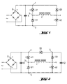
- a circuit known under the name H-bridge assumes a rectified and possibly by means of a capacitor K smoothed mains voltage and consists in Principle of two controlled valves, e.g. B. semiconductor switches V1 and V2, and two uncontrolled diodes D1 and D2. Connecting the from a network Generated so-called “intermediate circuit voltage” takes place - as shown in Fig. 1 - on a first bridge diagonal at connection points 1 and 2.
- One inductive load L lies above the other bridge diagonal between the connection points 3 and 4.
- the load L is any type of DC-fed inductance, like a solenoid valve coil or a motor field coil, conceivable.
- the capacitance of the smoothing capacitor K is comparative to be large, because this capacitor is basically two different ones Functions: On the one hand, it serves to reduce the rectification of the grid caused ripple of the DC voltage obtained and the function is completely independent of this after each switch-off of both semiconductor switches V1, V2 fed back into the intermediate circuit via the two diodes D1, D2 magnetic energy, the so-called “demagnetizing energy" of the Load L (coil).
- This double function means that the Dimensioning of the capacitor K for both functions or tasks must be respected.
- the capacitor K can never be made smaller than to take up the magnetic energy with an acceptable voltage increase required.
- the problem underlying the invention is, on the one hand, the network perturbations as well as the size of the smoothing capacity K significantly to reduce.
- the Invention by the entirety of the features specified in the claim defined and characterized in that the one with the positive pole Rectifier connected connecting nodes of the first bridge diagonal cut and between the two half-bridge branches one with respect to one Current flow direction from the positive to the negative DC pole of the rectifier reverse polarity decoupling diode is connected and that the Smoothing capacitor is divided into two separate capacitors, one of which one bridges the DC side of the rectifier as a smoothing capacitor and the other above that through the series connection of the second diode and the second controllable valve formed second half-bridge branch connected is and at the same time as a recovery capacitor for at least partial Takes over the demagnetization energy of the inductive load, especially to reduce network perturbations.
- the invention not only has the particular advantage that the one mentioned above Oversizing the smoothing capacitor K in the circuit arrangement 1 can be avoided, but especially the increasingly restrictive regulations on permissible current harmonics of the network can be better met, at least in part by the mentioned necessary oversizing of the smoothing capacitor K causes could be.
- the capacitor K from FIG. 1 divided into two capacities K1, K2.
- the one for smoothing and also for that Current harmonics in the network responsible part K1 remains unchanged of the previous capacitor K remained, while the other part K2, the Takes over the demagnetization energy from the inductive load L, directly to the second, also referred to as the "demagnetizing diode" Diode D2 is connected and is therefore parallel to the second Half-bridge diagonal, formed from the series connection of the second diode D2 and the second controlled semiconductor switch V2, which remains unchanged in the polarity already indicated in Fig. 1 are present.
- An additional effect that is particularly advantageous for some applications 2 is the suppression of high Inrush currents due to high smoothing capacities, as shown in the above explained reasons were previously required, so that possibly on special charging circuits can be dispensed with.
Landscapes
- Engineering & Computer Science (AREA)
- Power Engineering (AREA)
- Rectifiers (AREA)
Abstract
Description
- Fig. 1
- eine bereits erläuterte bekannte Gleichstromspeiseschaltung für Induktivitäten: und
- Fig. 2
- eine gemäß der Erfindung gestaltete und abgeänderte Gleichstromspeiseschaltung für Induktivitäten.
Claims (1)
- Gleichstromspeiseschaltung für Induktivitäten in Form einer Brückenschaltung mit einem Gleichrichter (G) mit gleichstomseitigem Glättungskondenstor über der einen, ersten Brückendiagonale (1, 2) und einer induktiven Last (L) über der anderen, zweiten Brückendiagonale (3, 4), wobei die beiden zwischen den Polen des Glättungskondensators liegenden Halbbrückenzweige einerseits aus der Reihenschaltung eines ersten steuerbaren Ventils (V1) und einer bezüglich einer Stromflussrichtung vom positiven zum negativen Pol des Gleichrichters in Sperrrichtung liegenden ersten Diode (D1) und andererseits aus einem zweiten steuerbaren Ventil (V2) und einer zweiten in der genannten Stromflussrichtung ebenfalls in Sperrichtung liegenden Diode (D2) bestehen,
dadurch gekennzeichnet, dassder mit dem positiven Pol des Gleichrichters (G) verbundene Anschlussknoten (1) der beiden Halbbrückenzweige der ersten Brückendiagonale aufgetrennt und zwischen die beiden Halbbrückenzweige eine in Bezug auf die genannte Stromflussrichtung in Sperrrichtung gepolte Entkopplungs-Diode (D3) geschaltet ist, und dassder Glättungskondensator in zwei getrennte Kapazitäten (K1, K2) aufgeteilt ist, von denen die eine (K1) als Glättungskapazität die Gleichstromseite des Gleichrichters (G) überbrückt und die andere (K2) über dem durch die Reihenschaltung der zweiten Diode (D2) und dem zweiten steuerbaren Ventil (V2) gebildeten zweiten Halbbrückenzweig angeschlossen ist und gleichzeitig als Rückspeisekondensator zur mindesten teilweisen Übernahme der Abmagnetisierungsenergie der induktiven Last (L) dient.
Applications Claiming Priority (2)
| Application Number | Priority Date | Filing Date | Title |
|---|---|---|---|
| DE10021785 | 2000-05-04 | ||
| DE10021785A DE10021785A1 (de) | 2000-05-04 | 2000-05-04 | Gleichstromspeiseschaltung für Induktivitäten |
Publications (3)
| Publication Number | Publication Date |
|---|---|
| EP1152517A2 true EP1152517A2 (de) | 2001-11-07 |
| EP1152517A3 EP1152517A3 (de) | 2004-01-14 |
| EP1152517B1 EP1152517B1 (de) | 2009-07-22 |
Family
ID=7640804
Family Applications (1)
| Application Number | Title | Priority Date | Filing Date |
|---|---|---|---|
| EP01810397A Expired - Lifetime EP1152517B1 (de) | 2000-05-04 | 2001-04-24 | Gleichstrompspeiseschaltung für Induktivitäten |
Country Status (5)
| Country | Link |
|---|---|
| US (1) | US6385062B2 (de) |
| EP (1) | EP1152517B1 (de) |
| JP (1) | JP4782939B2 (de) |
| CN (1) | CN1179472C (de) |
| DE (2) | DE10021785A1 (de) |
Family Cites Families (11)
| Publication number | Priority date | Publication date | Assignee | Title |
|---|---|---|---|---|
| US3710229A (en) * | 1971-06-11 | 1973-01-09 | Westinghouse Electric Corp | Integrator controlled inverter |
| DE2402317A1 (de) * | 1974-01-18 | 1975-07-24 | Krauss Maffei Ag | Verfahren zur steuerung eines gleichoder wechselstromstellers fuer induktive lasten |
| JPS5194529A (de) * | 1975-02-15 | 1976-08-19 | ||
| JPS5778382A (en) * | 1980-10-30 | 1982-05-17 | Fanuc Ltd | Driving circuit for dc motor |
| JPS6158971A (ja) * | 1984-04-13 | 1986-03-26 | Hitachi Ltd | 自動車用点火装置 |
| JPS63294297A (ja) * | 1987-05-26 | 1988-11-30 | Hitachi Electronics Eng Co Ltd | ユニポ−ラ型ステップモ−タの巻線電流回生方式 |
| US5303137A (en) * | 1991-12-04 | 1994-04-12 | Dawn Technologies, Ltd. | Multiresonant self-oscillating converter circuit |
| JPH09275697A (ja) * | 1996-04-04 | 1997-10-21 | Nippon Electric Ind Co Ltd | スイッチド・リラクタンスモータの駆動回路およびその制御方法 |
| JP3521649B2 (ja) * | 1996-09-09 | 2004-04-19 | 日産自動車株式会社 | モータの駆動回路 |
| DE19709264A1 (de) * | 1997-03-06 | 1998-09-10 | Hilti Ag | Verfahren zur Reduzierung von Rückwirkungen auf den Verlauf des einem Netz entnommenen Stroms bei induktiven Lasten und Vorrichtung zum Antreiben von Motoren nach diesem Verfahren |
| US6058026A (en) * | 1999-07-26 | 2000-05-02 | Lucent Technologies, Inc. | Multiple output converter having a single transformer winding and independent output regulation |
-
2000
- 2000-05-04 DE DE10021785A patent/DE10021785A1/de not_active Ceased
-
2001
- 2001-04-24 EP EP01810397A patent/EP1152517B1/de not_active Expired - Lifetime
- 2001-04-24 DE DE50114991T patent/DE50114991D1/de not_active Expired - Lifetime
- 2001-04-26 JP JP2001129459A patent/JP4782939B2/ja not_active Expired - Fee Related
- 2001-04-27 CN CNB01117157XA patent/CN1179472C/zh not_active Expired - Lifetime
- 2001-05-02 US US09/847,797 patent/US6385062B2/en not_active Expired - Lifetime
Also Published As
| Publication number | Publication date |
|---|---|
| US6385062B2 (en) | 2002-05-07 |
| CN1323092A (zh) | 2001-11-21 |
| EP1152517A3 (de) | 2004-01-14 |
| EP1152517B1 (de) | 2009-07-22 |
| JP2002010647A (ja) | 2002-01-11 |
| JP4782939B2 (ja) | 2011-09-28 |
| CN1179472C (zh) | 2004-12-08 |
| DE50114991D1 (de) | 2009-09-03 |
| DE10021785A1 (de) | 2001-12-06 |
| US20010053085A1 (en) | 2001-12-20 |
Similar Documents
| Publication | Publication Date | Title |
|---|---|---|
| DE102013225507B4 (de) | Schaltnetzteil und Batterieladegerät mit demselben | |
| DE102006014608B4 (de) | Filterschaltung und Spannungsversorgungseinheit | |
| DE60212463T2 (de) | Schaltnetzteil mit snubber-netzwerk | |
| DE102008028952A1 (de) | AC-DC-Zwischenkreis-Wandler mit sehr weitem AC-Eingangsspannungs-Bereich | |
| EP2237404A1 (de) | Wechselrichter mit zwei asymmetrischen Brückenschaltungen und einem Freilaufpfad zur Entkopplung von Gleich- und Wechselspannungsseite | |
| DE69118501T2 (de) | Wechselrichteranordnung | |
| DE102011006769A1 (de) | Leistungsumwandlungsschaltung | |
| WO2020064432A1 (de) | Ladeschaltung für einen fahrzeugseitigen elektrischen energiespeicher | |
| DE4400436C2 (de) | Umrichter | |
| EP0869605B1 (de) | Verfahren zur Reduzierung von Rückwirkungen auf den Verlauf des einem Netz entnommenen Stroms bei induktiven Lasten und Vorrichtung zum Antreiben von Motoren nach diesem Verfahren | |
| DE112019001203T5 (de) | Energie-umwandlungseinrichtung | |
| DE4426017C2 (de) | Stromversorgungsgerät, insbesondere Batterie-Ladegerät für Elektrofahrzeuge oder dergleichen | |
| DE10118040A1 (de) | DC-DC Konverter | |
| EP2507903B1 (de) | Flusswandler mit leistungsfaktorkorrektur | |
| DE69632163T2 (de) | Gleichstromwandler mit verbessertem Leistungsfaktor | |
| DE102018216233A1 (de) | Ladeschaltung für einen fahrzeugseitigen elektrischen Energiespeicher | |
| DE10138751B4 (de) | Wechselrichter mit schnellschaltenden ansteuerbaren elektronischen Schaltern, insbesondere IGBT-Schaltern, sowie Verfahren zur Ansteuerung eines derartigen Wechselrichters | |
| EP1152517B1 (de) | Gleichstrompspeiseschaltung für Induktivitäten | |
| DE112016004305T5 (de) | Stromversorgungsvorrichtung | |
| DE102013212229A1 (de) | Spannungsumsetzer und Verfahren zum Betreiben eines Spannungsumsetzers | |
| EP0293874A2 (de) | Verfahren und Schaltungsanordnung zur Zustandssteuerung für einen Schwingkreis in einem Resonanzwandler-Netzteil | |
| AT401591B (de) | Drehstrom-pulsgleichrichtersystem | |
| DE69013552T2 (de) | Gleichstromschaltwandler. | |
| EP2642652A1 (de) | Spannungszwischenkreisumrichter mit schlankem Zwischenkreis (F3E) mit zusätzlichem geregeltem Pufferzwischenkreis und Verfahren zu dessen Betrieb | |
| DE4413382C2 (de) | Drehstrom-Gleichrichterschaltung |
Legal Events
| Date | Code | Title | Description |
|---|---|---|---|
| PUAI | Public reference made under article 153(3) epc to a published international application that has entered the european phase |
Free format text: ORIGINAL CODE: 0009012 |
|
| AK | Designated contracting states |
Kind code of ref document: A2 Designated state(s): AT BE CH CY DE DK ES FI FR GB GR IE IT LI LU MC NL PT SE TR |
|
| AX | Request for extension of the european patent |
Free format text: AL;LT;LV;MK;RO;SI |
|
| PUAL | Search report despatched |
Free format text: ORIGINAL CODE: 0009013 |
|
| AK | Designated contracting states |
Kind code of ref document: A3 Designated state(s): AT BE CH CY DE DK ES FI FR GB GR IE IT LI LU MC NL PT SE TR |
|
| AX | Request for extension of the european patent |
Extension state: AL LT LV MK RO SI |
|
| RIC1 | Information provided on ipc code assigned before grant |
Ipc: 7H 02M 3/158 A Ipc: 7H 02M 1/00 B |
|
| 17P | Request for examination filed |
Effective date: 20040714 |
|
| AKX | Designation fees paid |
Designated state(s): CH DE FR GB LI NL SE |
|
| GRAP | Despatch of communication of intention to grant a patent |
Free format text: ORIGINAL CODE: EPIDOSNIGR1 |
|
| GRAS | Grant fee paid |
Free format text: ORIGINAL CODE: EPIDOSNIGR3 |
|
| GRAA | (expected) grant |
Free format text: ORIGINAL CODE: 0009210 |
|
| AK | Designated contracting states |
Kind code of ref document: B1 Designated state(s): CH DE FR GB LI NL SE |
|
| REG | Reference to a national code |
Ref country code: GB Ref legal event code: FG4D Free format text: NOT ENGLISH |
|
| REG | Reference to a national code |
Ref country code: CH Ref legal event code: EP |
|
| REF | Corresponds to: |
Ref document number: 50114991 Country of ref document: DE Date of ref document: 20090903 Kind code of ref document: P |
|
| REG | Reference to a national code |
Ref country code: SE Ref legal event code: TRGR |
|
| PLBE | No opposition filed within time limit |
Free format text: ORIGINAL CODE: 0009261 |
|
| STAA | Information on the status of an ep patent application or granted ep patent |
Free format text: STATUS: NO OPPOSITION FILED WITHIN TIME LIMIT |
|
| 26N | No opposition filed |
Effective date: 20100423 |
|
| REG | Reference to a national code |
Ref country code: FR Ref legal event code: PLFP Year of fee payment: 16 |
|
| REG | Reference to a national code |
Ref country code: FR Ref legal event code: PLFP Year of fee payment: 17 |
|
| REG | Reference to a national code |
Ref country code: FR Ref legal event code: PLFP Year of fee payment: 18 |
|
| PGFP | Annual fee paid to national office [announced via postgrant information from national office to epo] |
Ref country code: NL Payment date: 20200427 Year of fee payment: 20 Ref country code: FR Payment date: 20200420 Year of fee payment: 20 Ref country code: CH Payment date: 20200420 Year of fee payment: 20 Ref country code: DE Payment date: 20200420 Year of fee payment: 20 |
|
| PGFP | Annual fee paid to national office [announced via postgrant information from national office to epo] |
Ref country code: SE Payment date: 20200427 Year of fee payment: 20 Ref country code: GB Payment date: 20200427 Year of fee payment: 20 |
|
| REG | Reference to a national code |
Ref country code: DE Ref legal event code: R071 Ref document number: 50114991 Country of ref document: DE |
|
| REG | Reference to a national code |
Ref country code: NL Ref legal event code: MK Effective date: 20210423 |
|
| REG | Reference to a national code |
Ref country code: CH Ref legal event code: PL |
|
| REG | Reference to a national code |
Ref country code: GB Ref legal event code: PE20 Expiry date: 20210423 |
|
| REG | Reference to a national code |
Ref country code: SE Ref legal event code: EUG |
|
| PG25 | Lapsed in a contracting state [announced via postgrant information from national office to epo] |
Ref country code: GB Free format text: LAPSE BECAUSE OF EXPIRATION OF PROTECTION Effective date: 20210423 |