EP1152491A2 - Anordnung zur Kontaktierung von Flachfolienleitern - Google Patents
Anordnung zur Kontaktierung von Flachfolienleitern Download PDFInfo
- Publication number
- EP1152491A2 EP1152491A2 EP01110637A EP01110637A EP1152491A2 EP 1152491 A2 EP1152491 A2 EP 1152491A2 EP 01110637 A EP01110637 A EP 01110637A EP 01110637 A EP01110637 A EP 01110637A EP 1152491 A2 EP1152491 A2 EP 1152491A2
- Authority
- EP
- European Patent Office
- Prior art keywords
- housing
- contact
- arrangement according
- film
- end position
- Prior art date
- Legal status (The legal status is an assumption and is not a legal conclusion. Google has not performed a legal analysis and makes no representation as to the accuracy of the status listed.)
- Granted
Links
Images



Classifications
-
- H—ELECTRICITY
- H01—ELECTRIC ELEMENTS
- H01R—ELECTRICALLY-CONDUCTIVE CONNECTIONS; STRUCTURAL ASSOCIATIONS OF A PLURALITY OF MUTUALLY-INSULATED ELECTRICAL CONNECTING ELEMENTS; COUPLING DEVICES; CURRENT COLLECTORS
- H01R12/00—Structural associations of a plurality of mutually-insulated electrical connecting elements, specially adapted for printed circuits, e.g. printed circuit boards [PCB], flat or ribbon cables, or like generally planar structures, e.g. terminal strips, terminal blocks; Coupling devices specially adapted for printed circuits, flat or ribbon cables, or like generally planar structures; Terminals specially adapted for contact with, or insertion into, printed circuits, flat or ribbon cables, or like generally planar structures
- H01R12/50—Fixed connections
- H01R12/59—Fixed connections for flexible printed circuits, flat or ribbon cables or like structures
- H01R12/65—Fixed connections for flexible printed circuits, flat or ribbon cables or like structures characterised by the terminal
- H01R12/67—Fixed connections for flexible printed circuits, flat or ribbon cables or like structures characterised by the terminal insulation penetrating terminals
- H01R12/675—Fixed connections for flexible printed circuits, flat or ribbon cables or like structures characterised by the terminal insulation penetrating terminals with contacts having at least a slotted plate for penetration of cable insulation, e.g. insulation displacement contacts for round conductor flat cables
Definitions
- the invention relates to an arrangement for contacting Flat film conductors of a film with at least one contact with a first area to connect to the Flat foil conductor and a second area for further Contacting and with a housing for receiving the Contact, the housing having a first part with a front section with at least one contact chamber Establishment of the second area of contact and one rear section to accommodate the first area of the Has contact and the flat film conductor and one second part, which acts as a cover for the rear Section serves.
- the second part of the housing is in the insertion position. Then the film with the flat film conductor in the Housing inserted up to the stop. Then the second one Part pressed into the end position, the prongs of the Point the crown through the foil conductor and into it provided recesses. This is ensured that the flat film conductor from the teeth is contacted.
- the second part in the Insert position connected to the housing and therefore is captive.
- the film in the housing is kept safe. This is done by ripping and / or that Connect the housing parts together ultrasonic welding or hot caulking guaranteed.
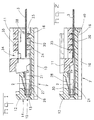
- Figure 1 shows a longitudinal section through a arrangement according to the invention in the insertion position inserted film.
- Figure 2 shows a longitudinal section through the Arrangement according to the invention according to Figure 1 in the end position with inserted film.
- Figure 3 shows a view of a second part of the Slide facing side.
- Figure 4 shows a perspective view of a contact an arrangement according to the invention.
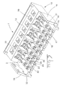
- Figure 5 shows a perspective view of a first Housing part with inserted contacts.
- Figure 6 shows a perspective view of a first Housing part with inserted contacts and attached second housing part in insertion position.
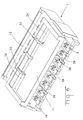
- FIG. 7 shows an arrangement according to the invention with a film in End position.
- the arrangement for contacting Flat film conductors consist of a housing 1 and at least one electrical contact 2.
- the contact 2 serves for contacting the flat foil conductors of a foil 3 on the one hand and for contacting a complementary Contact on the other.
- the structure of the contact 2 will now be shown in FIGS. 1, 2 and 5 are explained. It is the electrical contact 2 in the given embodiment for a socket contact. But it would also be possible instead a socket contact or a pin contact or otherwise to provide equipped contact.
- the contact 2 points a first area 20 for connection to a Falch film conductor and a second area 21 for Contacting a complementary contact pin.
- the first region 20 of contact 2 has a base plate 22 on, which are arranged one behind the other in the longitudinal direction Pointed crowns 23 and 23 '.
- the serrated crowns exist each made up of four prongs 24, which come from the base plate 22 are highlighted and turned upwards.
- At the end of the base plate on the film side is an off the base plate bent web 25. This web 25 serves as a stop when the contact 2 in the housing 1 is introduced.
- the second area 21 of the electrical contact 2 is in the Embodiment as a socket contact with four on the four sides arranged contact springs 26 formed.
- the Contact springs are surrounded by an outer spring 27, the has a detent spring tongue 28.
- the detent spring tongue 28 serves to lock and secure the contact in the Housing 1.
- the outer spring 27 has next to the Latch spring tongue 28 also has a polarization rib 29 on, which ensures that contact 2 is correct polarized is introduced into the housing 1.
- the housing 1 consists of a first part 10 and a second part 11.
- the first part 10 has a front Section 12 with at least one contact chamber 13.
- the Contact chamber 13 serves to receive a contact 2. It there are several in the front section 12 of the first part 10 Contact chambers 13 arranged side by side in a row.
- the contact chambers 13 face the front end 14 of the Housing 1 a through hole 15 for an electrical Contact pin.
- In the contact chambers 13 is in the The main thing is the second area 21 of the contact 2 added.
- the first region 20 of the electrical contact 2 is in the rear section 16 of the first part 10 of the housing 1 added.
- the rear section 16 consists of Essentially from a base plate 17 on which the first Areas 20 of the contacts 2 rest. This base plate 17th also has stops 18 for interaction with the webs 25 of the contacts.
- the rear part shows two Side walls 19 on the second part 11 of the Interact housing 1.
- the front section 12 of the first part 10 faces above each chamber has a window 30 in which the latch spring tongue 28 of an electrical contact locked. This will a first backup of the contacts 2 in the housing 1 guaranteed.
- FIG 3 is a view of the second part 11 of the Housing 1 from the side facing the film shown.
- This cover is parallel to the base plate 17th applied to the first part 10 of the housing 1.
- the contacts are first in the housing with a second part in the pre-locking position inserted and then inserted the film.
- the housing has stops 33 against which the film starts should. These stops designed as wall parts are used also for guiding the second part 11 during insertion this part.
- the second part 11 also points Window openings 34 through which are determined can whether the film up to the stops 33 in the housing 1 was introduced. If this is the case, the second can Part 11 are brought into the end position.
- the second part 11, has recesses 35 which are used to receive the prongs 24 of the tooth crowns 23 serve. The recesses 35 are such that they have a slope that causes the teeth to go out when inserted be bent. This ensures that the Contact point is kept safe.
- the second part 11 also has ribs 36 which for Hold down and fix the film.
- These ribs 36 can, for example, from an elastically deformable Material can be shaped such that it presses the film exercise to ensure contacting. A This also ensures contacting achieved that further trapezoidal ribs 37 are provided are used to connect the second part 11 to the rear Section 16 of the first part 10 with ultrasound weld.
- Posts 38 are provided which cooperate with openings 39.
- the posts 38 engage in the openings in the end position 39 and lock by means of complementary locking means 40 in these. This additional locking means that secure attachment of the second part 11 to the first part 10 guaranteed.
- the second serves Part 11 also as a second contact securing for contact 2 in the housing 1 when it is in the end position.
- a particularly advantageous introduction of the second part is given in the first part when the housing in a housing is introduced. It can then be provided be that the outer casing with slot grooves and the second To provide the part with the corresponding sliding blocks, such that when the housing is inserted into the surrounding housing the second part is forced into its end position.
Landscapes
- Coupling Device And Connection With Printed Circuit (AREA)
- Multi-Conductor Connections (AREA)
Abstract
Description
Claims (18)
- Anordnung zur Kontaktierung von Flachfolienleitern einer Folie (3) mit zumindest einem Kontakt (2) mit einem ersten Bereich (20) zur Verbindung mit dem Flachfolienleiter und einem zweiten Bereich (21) zur weiteren Kontaktierung und mit einem Gehäuse (1) zur Aufnahme des Kontaktes, wobei das Gehäuse einen ersten Teil (10) mit einem vorderen Abschnitt (12) mit zumindest einer Kontaktkammer (13) zur Aufnahme des zweiten Bereiches des Kontaktes und einem hinteren Abschnitt (16) zur Aufnahme des ersten Bereiches des Kontaktes und des Flachfolienleiters aufweist und einen zweiten Teil (11) aufweist, der als Abdeckung des hinteren Abschnittes dient, dadurch gekennzeichnet, dass der erste Bereich des Kontaktes eine Basisplatte (22) aufweist mit zumindest einer Zackenkrone (23, 23') mit mehreren Zacken (24), dass der zweite Teil des Gehäuses Aussparungen (35) zur Aufnahme der Zacken der Zackenkrone aufweist und als Pressteil ausgebildet ist, derart, dass beim Aufbringen des zweiten Teils auf den ersten Teil die Zacken der Zackenkrone den Folienleiter durchdringen und kontaktieren.
- Anordnung nach Anspruch 1, dadurch gekennzeichnet, dass der zweite Teil in einer Einbringstellung, in der der Kontakt und die Folie mit dem Flachfolienleiter in das Gehäuse einbringbar sind, und in einer Endstellung in der der Flachfolienleiter kontaktiert ist, mit dem Gehäuse verbindbar ist.
- Anordnung nach Anspruch 2, dadurch gekennzeichnet, dass der zweite Teil in der Endstellung am Gehäuse verrastet ist.
- Anordnung nach Anspruch 2, dadurch gekennzeichnet, dass der zweite Teil in der Einbringstellung am Gehäuse verrastet ist.
- Anordnung nach Anspruch 2, dadurch gekennzeichnet, dass der zweite Teil in der Einbringstellung am Gehäuse angespritzt ist.
- Anordnung nach Anspruch 2, dadurch gekennzeichnet, dass der zweite Teil in der Endstellung mit dem Gehäuse ultraschallverschweissbar ist.
- Anordnung nach Anspruch 2, dadurch gekennzeichnet, dass der zweite Teil in der Endstellung mit dem Gehäuse heissverstemmbar ist.
- Anordnung nach Anspruch 2, dadurch gekennzeichnet, dass der zweite Teil in der Endstellung mit der Folie ultraschallverschweissbar ist.
- Anordnung nach einem der Ansprüche 1 bis 7, dadurch gekennzeichnet, dass mehrere Zackenkronen in Längsrichtung des Kontaktes hintereinander angeordnet sind.
- Anordnung nach einem der Ansprüche 1 bis 9, dadurch gekennzeichnet, dass die Aussparungen eine Schräge aufweisen, die bewirkt, dass die Zacken beim Einbringen des zweiten Teil in die Endstellung nach innen oder nach aussen verbogen werden.
- Anordnung nach einem der Ansprüche 1 bis 10, dadurch gekennzeichnet, dass der zweite Teil und der hintere Abschnitt des Gehäuses komplementäre Pfosten (38) und Öffnungen (39) haben, als Zugentlastung und Fixierung durch Durchtritt durch die Folie an vorgegebenen Löchern.
- Anordnung nach Anspruch 11, dadurch gekennzeichnet, dass der die Pfosten (38) und die Öffnungen (39) komplementäre Rastmittel (40) aufweisen, die das zweite Teil in der Endstellung fixieren.
- Anordnung nach einem der Ansprüche 1 bis 12, dadurch gekennzeichnet, dass der zweite Teil Rippen (36) zum Niederhalten und Fixieren der Folie aufweist.
- Anordnung nach Anspruch 13, dadurch gekennzeichnet, dass die Rippen (36) aus einem elastisch verformbaren Material sind.
- Anordnung nach einem der Ansprüche 1 bis 14, dadurch gekennzeichnet, dass das Gehäuse einen Anschlag (33) für die Folie aufweist.
- Anordnung nach einem der Ansprüche 1 bis 15, dadurch gekennzeichnet, dass der zweite Teil Fensteröffnungen (34) zum Erkennen der Lage der Folie aufweist.
- Anordnung nach einem der Ansprüche 1 bis 16, dadurch gekennzeichnet, dass das zweite Teil zwangsgeführt in die Endstellung gebracht wird.
- Anordnung nach Anspruch 17, dadurch gekennzeichnet, dass das Gehäuse in ein Umgehäuse einbringbar ist und beim Einbringen das zweite Teil in seine Endlage zwangsgeführt wird.
Priority Applications (1)
| Application Number | Priority Date | Filing Date | Title |
|---|---|---|---|
| EP20010110637 EP1152491B1 (de) | 2000-05-04 | 2001-05-02 | Anordnung zur Kontaktierung von Flachfolienleitern |
Applications Claiming Priority (3)
| Application Number | Priority Date | Filing Date | Title |
|---|---|---|---|
| EP00109572 | 2000-05-04 | ||
| EP00109572 | 2000-05-04 | ||
| EP20010110637 EP1152491B1 (de) | 2000-05-04 | 2001-05-02 | Anordnung zur Kontaktierung von Flachfolienleitern |
Publications (3)
| Publication Number | Publication Date |
|---|---|
| EP1152491A2 true EP1152491A2 (de) | 2001-11-07 |
| EP1152491A3 EP1152491A3 (de) | 2004-06-16 |
| EP1152491B1 EP1152491B1 (de) | 2006-03-08 |
Family
ID=26070897
Family Applications (1)
| Application Number | Title | Priority Date | Filing Date |
|---|---|---|---|
| EP20010110637 Expired - Lifetime EP1152491B1 (de) | 2000-05-04 | 2001-05-02 | Anordnung zur Kontaktierung von Flachfolienleitern |
Country Status (1)
| Country | Link |
|---|---|
| EP (1) | EP1152491B1 (de) |
Cited By (2)
| Publication number | Priority date | Publication date | Assignee | Title |
|---|---|---|---|---|
| FR2886472A1 (fr) * | 2005-05-27 | 2006-12-01 | Valeo Electronique Sys Liaison | Boitier de connexion pour cables plats |
| WO2008033318A1 (en) * | 2006-09-11 | 2008-03-20 | Molex Incorporated | Relay connector for flexible cables |
Family Cites Families (5)
| Publication number | Priority date | Publication date | Assignee | Title |
|---|---|---|---|---|
| US4083615A (en) * | 1977-01-27 | 1978-04-11 | Amp Incorporated | Connector for terminating a flat multi-wire cable |
| BR8701399A (pt) * | 1986-04-03 | 1988-01-05 | Du Pont | Tira de contacto e processo para a producao de uma fileira de conectores de grampo de borda,ou de um unico conector de grampo de borda |
| JPH01118588A (ja) * | 1987-10-30 | 1989-05-11 | Toyota Motor Corp | 自動車用パッキン材料 |
| TW277168B (de) * | 1994-08-12 | 1996-06-01 | Whitaker Corp | |
| US5860832A (en) * | 1997-01-29 | 1999-01-19 | Ut Automotive Dearborn, Inc. | Method for connecting flat flexible cable and a connector |
-
2001
- 2001-05-02 EP EP20010110637 patent/EP1152491B1/de not_active Expired - Lifetime
Cited By (4)
| Publication number | Priority date | Publication date | Assignee | Title |
|---|---|---|---|---|
| FR2886472A1 (fr) * | 2005-05-27 | 2006-12-01 | Valeo Electronique Sys Liaison | Boitier de connexion pour cables plats |
| WO2008033318A1 (en) * | 2006-09-11 | 2008-03-20 | Molex Incorporated | Relay connector for flexible cables |
| US8043113B2 (en) | 2006-09-11 | 2011-10-25 | Molex Incorporated | Relay connector for flexible cables |
| CN101536267B (zh) * | 2006-09-11 | 2014-08-13 | 莫列斯公司 | 用于柔性电缆的继电器连接器 |
Also Published As
| Publication number | Publication date |
|---|---|
| EP1152491B1 (de) | 2006-03-08 |
| EP1152491A3 (de) | 2004-06-16 |
Similar Documents
| Publication | Publication Date | Title |
|---|---|---|
| DE4131768B4 (de) | Elektrischer Verbinder mit Doppelverriegelung | |
| EP1503457B1 (de) | Kontaktbuchse für einen Flachstecker | |
| DE102016221351A1 (de) | Flachkontaktbuchse mit Ausleger | |
| DE4015915A1 (de) | Steckdose fuer eine mehrpolige steckverbindung | |
| DE68913805T2 (de) | Klammer für die Zugentlastung eines Kabels. | |
| DE202004021593U1 (de) | Batteriepack und Elektrowerkzeug | |
| EP2824770B1 (de) | Mehrfachsteckdose | |
| DE10331229A1 (de) | Kontaktanordnung bei einer elektrischen Steckverbindung | |
| EP1376775A1 (de) | Elektrischer Steckverbinder | |
| DE3337511A1 (de) | Verriegelbare steckerverbindung | |
| DE102004052225A1 (de) | Verbinder | |
| DE10301279B4 (de) | Verbinder | |
| EP0822615B1 (de) | Elektrische Kontaktfeder | |
| DE10301281A1 (de) | Verbinder | |
| DE2004332B2 (de) | Anschlußstecker für Leiter-Steckkarten | |
| EP2475057B2 (de) | Kabeltragvorrichtung | |
| DE4331036C2 (de) | Schneidklemm-Verbindungsstecker | |
| EP1152491B1 (de) | Anordnung zur Kontaktierung von Flachfolienleitern | |
| DE19949386C2 (de) | Geräte-Anschlusskasten mit Schneidtechnik | |
| DE102021118676B4 (de) | Stromführende Halteklemme | |
| DE2716393A1 (de) | Kontaktelement zum einsatz in die kontaktkammer eines isolierkoerpers | |
| DE102021132254A1 (de) | Elektrische Federklemmen-Verbindungsvorrichtung mit Aktuator und mehrpoliger Steckverbinder mit einer Vielzahl solcher Vorrichtungen | |
| DE29509313U1 (de) | Anordnung zum Halten eines zu einer im wesentlichen U-förmigen Gestalt zusammengedrückten Federelements an einer vorbestimmten Stelle | |
| DE10061942C1 (de) | Sammelschienenadapter | |
| BE1032383B1 (de) | Halterahmen für einen Steckverbinder |
Legal Events
| Date | Code | Title | Description |
|---|---|---|---|
| PUAI | Public reference made under article 153(3) epc to a published international application that has entered the european phase |
Free format text: ORIGINAL CODE: 0009012 |
|
| AK | Designated contracting states |
Kind code of ref document: A2 Designated state(s): AT BE CH CY DE DK ES FI FR GB GR IE IT LI LU MC NL PT SE TR |
|
| AX | Request for extension of the european patent |
Free format text: AL;LT;LV;MK;RO;SI |
|
| PUAL | Search report despatched |
Free format text: ORIGINAL CODE: 0009013 |
|
| AK | Designated contracting states |
Kind code of ref document: A3 Designated state(s): AT BE CH CY DE DK ES FI FR GB GR IE IT LI LU MC NL PT SE TR |
|
| AX | Request for extension of the european patent |
Extension state: AL LT LV MK RO SI |
|
| 17P | Request for examination filed |
Effective date: 20041021 |
|
| AKX | Designation fees paid |
Designated state(s): DE FR GB IT |
|
| 17Q | First examination report despatched |
Effective date: 20050201 |
|
| GRAP | Despatch of communication of intention to grant a patent |
Free format text: ORIGINAL CODE: EPIDOSNIGR1 |
|
| GRAS | Grant fee paid |
Free format text: ORIGINAL CODE: EPIDOSNIGR3 |
|
| GRAA | (expected) grant |
Free format text: ORIGINAL CODE: 0009210 |
|
| AK | Designated contracting states |
Kind code of ref document: B1 Designated state(s): DE FR GB IT |
|
| PG25 | Lapsed in a contracting state [announced via postgrant information from national office to epo] |
Ref country code: IT Free format text: LAPSE BECAUSE OF FAILURE TO SUBMIT A TRANSLATION OF THE DESCRIPTION OR TO PAY THE FEE WITHIN THE PRESCRIBED TIME-LIMIT;WARNING: LAPSES OF ITALIAN PATENTS WITH EFFECTIVE DATE BEFORE 2007 MAY HAVE OCCURRED AT ANY TIME BEFORE 2007. THE CORRECT EFFECTIVE DATE MAY BE DIFFERENT FROM THE ONE RECORDED. Effective date: 20060308 |
|
| REG | Reference to a national code |
Ref country code: GB Ref legal event code: FG4D Free format text: NOT ENGLISH |
|
| REF | Corresponds to: |
Ref document number: 50109126 Country of ref document: DE Date of ref document: 20060504 Kind code of ref document: P |
|
| GBT | Gb: translation of ep patent filed (gb section 77(6)(a)/1977) |
Effective date: 20060621 |
|
| ET | Fr: translation filed | ||
| PLBE | No opposition filed within time limit |
Free format text: ORIGINAL CODE: 0009261 |
|
| STAA | Information on the status of an ep patent application or granted ep patent |
Free format text: STATUS: NO OPPOSITION FILED WITHIN TIME LIMIT |
|
| 26N | No opposition filed |
Effective date: 20061211 |
|
| PGFP | Annual fee paid to national office [announced via postgrant information from national office to epo] |
Ref country code: GB Payment date: 20080529 Year of fee payment: 8 |
|
| GBPC | Gb: european patent ceased through non-payment of renewal fee |
Effective date: 20090502 |
|
| REG | Reference to a national code |
Ref country code: FR Ref legal event code: ST Effective date: 20100129 |
|
| PG25 | Lapsed in a contracting state [announced via postgrant information from national office to epo] |
Ref country code: FR Free format text: LAPSE BECAUSE OF NON-PAYMENT OF DUE FEES Effective date: 20090602 |
|
| PGFP | Annual fee paid to national office [announced via postgrant information from national office to epo] |
Ref country code: FR Payment date: 20080519 Year of fee payment: 8 |
|
| PG25 | Lapsed in a contracting state [announced via postgrant information from national office to epo] |
Ref country code: GB Free format text: LAPSE BECAUSE OF NON-PAYMENT OF DUE FEES Effective date: 20090502 |
|
| REG | Reference to a national code |
Ref country code: DE Ref legal event code: R081 Ref document number: 50109126 Country of ref document: DE Owner name: TE CONNECTIVITY GERMANY GMBH, DE Free format text: FORMER OWNER: TYCO ELECTRONICS AMP GMBH, 64625 BENSHEIM, DE |
|
| PGFP | Annual fee paid to national office [announced via postgrant information from national office to epo] |
Ref country code: DE Payment date: 20190416 Year of fee payment: 19 |
|
| REG | Reference to a national code |
Ref country code: DE Ref legal event code: R119 Ref document number: 50109126 Country of ref document: DE |
|
| PG25 | Lapsed in a contracting state [announced via postgrant information from national office to epo] |
Ref country code: DE Free format text: LAPSE BECAUSE OF NON-PAYMENT OF DUE FEES Effective date: 20201201 |