EP1152283B1 - Microdisplay system - Google Patents
Microdisplay system Download PDFInfo
- Publication number
- EP1152283B1 EP1152283B1 EP01106691A EP01106691A EP1152283B1 EP 1152283 B1 EP1152283 B1 EP 1152283B1 EP 01106691 A EP01106691 A EP 01106691A EP 01106691 A EP01106691 A EP 01106691A EP 1152283 B1 EP1152283 B1 EP 1152283B1
- Authority
- EP
- European Patent Office
- Prior art keywords
- light
- wave
- guide
- microdisplay
- color
- Prior art date
- Legal status (The legal status is an assumption and is not a legal conclusion. Google has not performed a legal analysis and makes no representation as to the accuracy of the status listed.)
- Expired - Lifetime
Links
- 239000003086 colorant Substances 0.000 claims description 6
- 239000000975 dye Substances 0.000 description 23
- 239000004973 liquid crystal related substance Substances 0.000 description 18
- 230000005540 biological transmission Effects 0.000 description 7
- 230000010287 polarization Effects 0.000 description 7
- XUIMIQQOPSSXEZ-UHFFFAOYSA-N Silicon Chemical compound [Si] XUIMIQQOPSSXEZ-UHFFFAOYSA-N 0.000 description 6
- 229910052710 silicon Inorganic materials 0.000 description 6
- 239000010703 silicon Substances 0.000 description 6
- 239000000463 material Substances 0.000 description 5
- 230000003287 optical effect Effects 0.000 description 4
- 239000011521 glass Substances 0.000 description 3
- 230000003190 augmentative effect Effects 0.000 description 2
- 238000005286 illumination Methods 0.000 description 2
- 238000012986 modification Methods 0.000 description 2
- 230000004048 modification Effects 0.000 description 2
- 230000000153 supplemental effect Effects 0.000 description 2
- 230000004913 activation Effects 0.000 description 1
- 238000005516 engineering process Methods 0.000 description 1
- 239000000835 fiber Substances 0.000 description 1
- 239000003550 marker Substances 0.000 description 1
- 239000013589 supplement Substances 0.000 description 1
Images

Classifications
-
- G—PHYSICS
- G02—OPTICS
- G02B—OPTICAL ELEMENTS, SYSTEMS OR APPARATUS
- G02B6/00—Light guides; Structural details of arrangements comprising light guides and other optical elements, e.g. couplings
- G02B6/0001—Light guides; Structural details of arrangements comprising light guides and other optical elements, e.g. couplings specially adapted for lighting devices or systems
- G02B6/0003—Light guides; Structural details of arrangements comprising light guides and other optical elements, e.g. couplings specially adapted for lighting devices or systems the light guides being doped with fluorescent agents
-
- G—PHYSICS
- G02—OPTICS
- G02F—OPTICAL DEVICES OR ARRANGEMENTS FOR THE CONTROL OF LIGHT BY MODIFICATION OF THE OPTICAL PROPERTIES OF THE MEDIA OF THE ELEMENTS INVOLVED THEREIN; NON-LINEAR OPTICS; FREQUENCY-CHANGING OF LIGHT; OPTICAL LOGIC ELEMENTS; OPTICAL ANALOGUE/DIGITAL CONVERTERS
- G02F1/00—Devices or arrangements for the control of the intensity, colour, phase, polarisation or direction of light arriving from an independent light source, e.g. switching, gating or modulating; Non-linear optics
- G02F1/01—Devices or arrangements for the control of the intensity, colour, phase, polarisation or direction of light arriving from an independent light source, e.g. switching, gating or modulating; Non-linear optics for the control of the intensity, phase, polarisation or colour
- G02F1/13—Devices or arrangements for the control of the intensity, colour, phase, polarisation or direction of light arriving from an independent light source, e.g. switching, gating or modulating; Non-linear optics for the control of the intensity, phase, polarisation or colour based on liquid crystals, e.g. single liquid crystal display cells
- G02F1/133—Constructional arrangements; Operation of liquid crystal cells; Circuit arrangements
- G02F1/1333—Constructional arrangements; Manufacturing methods
- G02F1/1335—Structural association of cells with optical devices, e.g. polarisers or reflectors
- G02F1/1336—Illuminating devices
- G02F1/133618—Illuminating devices for ambient light
-
- G—PHYSICS
- G02—OPTICS
- G02F—OPTICAL DEVICES OR ARRANGEMENTS FOR THE CONTROL OF LIGHT BY MODIFICATION OF THE OPTICAL PROPERTIES OF THE MEDIA OF THE ELEMENTS INVOLVED THEREIN; NON-LINEAR OPTICS; FREQUENCY-CHANGING OF LIGHT; OPTICAL LOGIC ELEMENTS; OPTICAL ANALOGUE/DIGITAL CONVERTERS
- G02F1/00—Devices or arrangements for the control of the intensity, colour, phase, polarisation or direction of light arriving from an independent light source, e.g. switching, gating or modulating; Non-linear optics
- G02F1/01—Devices or arrangements for the control of the intensity, colour, phase, polarisation or direction of light arriving from an independent light source, e.g. switching, gating or modulating; Non-linear optics for the control of the intensity, phase, polarisation or colour
- G02F1/13—Devices or arrangements for the control of the intensity, colour, phase, polarisation or direction of light arriving from an independent light source, e.g. switching, gating or modulating; Non-linear optics for the control of the intensity, phase, polarisation or colour based on liquid crystals, e.g. single liquid crystal display cells
- G02F1/133—Constructional arrangements; Operation of liquid crystal cells; Circuit arrangements
- G02F1/1333—Constructional arrangements; Manufacturing methods
- G02F1/1335—Structural association of cells with optical devices, e.g. polarisers or reflectors
- G02F1/1336—Illuminating devices
- G02F1/133621—Illuminating devices providing coloured light
- G02F1/133622—Colour sequential illumination
-
- G—PHYSICS
- G02—OPTICS
- G02F—OPTICAL DEVICES OR ARRANGEMENTS FOR THE CONTROL OF LIGHT BY MODIFICATION OF THE OPTICAL PROPERTIES OF THE MEDIA OF THE ELEMENTS INVOLVED THEREIN; NON-LINEAR OPTICS; FREQUENCY-CHANGING OF LIGHT; OPTICAL LOGIC ELEMENTS; OPTICAL ANALOGUE/DIGITAL CONVERTERS
- G02F1/00—Devices or arrangements for the control of the intensity, colour, phase, polarisation or direction of light arriving from an independent light source, e.g. switching, gating or modulating; Non-linear optics
- G02F1/01—Devices or arrangements for the control of the intensity, colour, phase, polarisation or direction of light arriving from an independent light source, e.g. switching, gating or modulating; Non-linear optics for the control of the intensity, phase, polarisation or colour
- G02F1/13—Devices or arrangements for the control of the intensity, colour, phase, polarisation or direction of light arriving from an independent light source, e.g. switching, gating or modulating; Non-linear optics for the control of the intensity, phase, polarisation or colour based on liquid crystals, e.g. single liquid crystal display cells
- G02F1/133—Constructional arrangements; Operation of liquid crystal cells; Circuit arrangements
- G02F1/1333—Constructional arrangements; Manufacturing methods
- G02F1/1335—Structural association of cells with optical devices, e.g. polarisers or reflectors
- G02F1/1336—Illuminating devices
- G02F1/133626—Illuminating devices providing two modes of illumination, e.g. day-night
-
- Y—GENERAL TAGGING OF NEW TECHNOLOGICAL DEVELOPMENTS; GENERAL TAGGING OF CROSS-SECTIONAL TECHNOLOGIES SPANNING OVER SEVERAL SECTIONS OF THE IPC; TECHNICAL SUBJECTS COVERED BY FORMER USPC CROSS-REFERENCE ART COLLECTIONS [XRACs] AND DIGESTS
- Y10—TECHNICAL SUBJECTS COVERED BY FORMER USPC
- Y10S—TECHNICAL SUBJECTS COVERED BY FORMER USPC CROSS-REFERENCE ART COLLECTIONS [XRACs] AND DIGESTS
- Y10S385/00—Optical waveguides
- Y10S385/901—Illuminating or display apparatus
Definitions
- the present invention relates generally to video and graphics microdisplay systems, and more particularly to a system for the illumination of microdisplays.
- liquid crystal material which forms the optical component of the microdisplay
- the liquid crystal material is placed directly on a silicon integrated circuit, or pixel array, under a transparent cover and the signals to turn the individual picture elements, or pixels, of the microdisplay on and off are generated on the silicon integrated circuit.
- microdisplay is used since the display in a typical embodiment has an array of 1,024 x 768 pixels (the individual pixel size is approximately 12 ⁇ ) and the silicon die is about 1.3 cm x 1 cm in area.
- the microdisplay system works by having light from an ordinary light source pass through an illuminator, which converts non-polarized light from the ordinary light source into a polarized light beam. The polarized light beam is then directed onto the microdisplay. The microdisplay will reflect the light in a manner such that the plane of polarization of the light will or will not be rotated. The light then is reflected back to the illuminator which acts as an analyzer and causes the pixels to be bright or dark depending on whether the plane of polarization was rotated. The bright and dark pixels form a viewing image.
- microdisplays continue to expand. In one application, they are used for viewfinders for digital cameras and camcorders. In another, two microdisplays are fixed to a frame, such as eyeglasses, thereby giving a user a virtual image of a virtual computer screen which is very lightweight and also very private.
- Document WO 99/34246 describes a head-up display having LEDs as a source of light, a reflective display device based on a LCD-display, a beam splitter being inclined to the LCD-display as well as to the LEDs producing a virtual image that is to be viewed by a viewer.
- Document US 4,884,860 discloses a fiber marker having a cylindrical phosphorescent layer which is sandwiched between a pair of coaxial optical waveguides concentrating the impinging ambient light to the phosphorescent layer leading to a higher efficiency with regard to the accumulated and reemitted light.
- microdisplays are small enough to be portable, batteries are used to provide power to illuminate the microdisplays. To minimize battery weight and maximize battery life, power consumption of the microdisplay must be minimized. High power consumption is one of the major problems with microdisplays. Attempts have been made in the art to use ambient light to illuminate microdisplays. However, the intensity and energy density of ambient light alone is generally insufficient to adequately illuminate microdisplays.
- the present invention provides a micro display system that uses ambient light to illuminate the microdisplay.
- a wave-guide has a dye embedded therein which absorbs ambient light through the surfaces of the wave-guide and re-emits an augmented light, which is captured by the wave-guide.
- Total internal reflection in the wave-guide and reflection from a reflector at one end of the wave-guide direct substantially all the light through a light-transmissive end to an illuminator for illuminating the microdisplay.
- the microdisplay has a plurality of pixels which are activated to reflect light back through the illuminator for viewing the microdisplay image. This approach minimizes power usage and prolongs battery life that is particularly useful in portable microdisplay systems.
- the present invention further provides a microdisplay system that uses ambient light to illuminate the microdisplay in color.
- a wave-guide has different dyes embedded in it which absorb ambient light and re-emit light in the three primary colors, namely red, green and blue.
- Total internal reflection in the wave-guide and reflection from a reflector at the end of the wave-guide direct the re-emitted light through the transmissive end into a solid-state color wheel.
- the solid-state color wheel is controlled by the integrated circuit to selectively permit the transmission of individual color lights to an illuminator for illuminating the microdisplay in synchronization with the activation of the pixels.
- the pixels are activated to reflect light back through the illuminator for viewing the microdisplay image.
- the present invention further provides a microdisplay system that uses ambient light to illuminate the microdisplay in color.
- Three wave-guides have different dyes embedded in them which absorb ambient light and re-emit light in the three primary colors, namely red, green and blue.
- Total internal reflections in the wave-guide and reflections from reflectors at the ends of the wave-guides direct the re-emitted light through the transmissive ends into liquid crystal (LC) shutters.
- LC liquid crystal
- Each of the LC shutters is independently controlled to turn on or shut off the transmission of the respective color light through the respective LC shutters to a coupler which directs the light to an illuminator for illuminating the microdisplay.
- the microdisplay has a plurality of pixels which are activated to reflect light back through the illuminator for viewing the microdisplay image. This approach minimizes power usage and prolongs battery life that is particularly useful in portable microdisplay systems.
- the present invention further provides a microdisplay system having an auxiliary, powered light source for use with the wave-guides for supplemental illumination of the microdisplay.
- the camera 10 includes optics 12 and an image sensor such as a charge coupled device (CCD) 14.
- CCD charge coupled device
- the CCD 14 sends a digitized image to an integrated circuit 16 which controls a microdisplay 18.
- the microdisplay 18 contains a liquid crystal material, which is placed directly on a silicon integrated circuit having an array of individual picture elements, or pixels.
- the typical array has an array of 1,024 x 768 pixels (the individual pixel size is approximately 12 ⁇ ) and the silicon die is about 1.3 cm x 1 cm in area.
- the liquid crystal responds to signals generated on the silicon integrated circuit under the control of the integrated circuit 16 to activate the pixels so as to change the plane of polarization of the light directed at the microdisplay 18 to match the image falling on the CCD 14.
- the microdisplay 18 is illuminated by polarized light passing through a light beamsplitter, or an illuminator 22, which is a polarizer which converts ordinary, non-polarized light into polarized light. Ordinary light is provided to one side of the illuminator 22 and is reflected out at right angles onto the microdisplay 18. The microdisplay 18 will reflect the light back in a manner such that the plane of polarization of the reflected light will or will not be rotated. The reflected light then is reflected back to the illuminator 22 which acts as an analyzer and makes the pixels appear to be reflective or non-reflective (dark) depending on whether the plane of polarization of the polarized light was rotated.
- a user sees the image on the microdisplay 18 through the illuminator 22 and an eyepiece or a viewfinder 20.
- the reflective and dark pixels form the viewing image with the reflective pixels providing light of the color of the polarized light.
- the non-polarized light is provided by a wave-guide 24.
- the wave-guide 24 is of an optical material such as glass or plastic with or without a low index of refraction sheathing, containing a conventional light-responsive dye 26, which absorbs light at a broad set of frequencies and emits the light energy at another, narrower set of frequencies. It is formed with a top, bottom, and side surfaces 28, a light-transmissive front end 34, and a back end 36 having a reflective device 38, such as mirroring.
- the wave-guide 24 has its surfaces 28 exposed to an ordinary light from an ambient light source 40 and is shaped to direct the majority of light falling on the surfaces 28 to the light-transmissive front end 34.
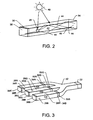
- FIG. 2 therein is shown a wave-guide 42 which shows the basic principle of operation of the wave-guides of the present invention.
- the same elements as in FIG. 1 are shown with the same number.
- the wave-guide 42 is shown straight, but it would be understood that it might be in any configuration required to fit in the microdevice using system in which it is used.
- the wave-guide 42 could be configured to form the wave-guide 24 of FIG. 1.
- the one molecule of dye 26 absorbs light from the ambient light source 40 and re-emits it as re-emitted light 44 in all directions. Most of the re-emitted light 44 is trapped inside the wave-guide 42 by reflection from the material-air boundary or a refractive sheathing. The re-emitted light 44 re-emitted towards the back end 36 is reflected by the reflective device 38 forward through the light-transmissive front end 34 of the wave-guide 42.
- the light-transmissive front end 34 may be roughened as an option to produce a diffuse source for the illuminator 22.
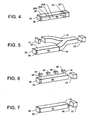
- a wave-guide 42R has surfaces 28R, a light-transmissive front-end 34R, a back end 36R with a reflective device 38R, and a dye 26R embedded therein.
- the wave-guide 42G has surfaces 28G, a light-transmissive front end 34G, a back end 36G with a reflective device 38G, and a dye 26G embedded therein.
- the wave-guide 42B has surfaces 28B, a front-end 34B, a back end 36B with a reflective device 38B, and a dye 26G embedded therein.
- the dyes 26R, 26G, and 26B collect ambient light through the respective surfaces 28R, 28G, and 28B and re-emit light of red (R), green (G), and blue (B) color, respectively. It would be evident to those skilled in the art that other color combinations may be used with fewer or greater numbers of colors depending upon the application.
- LC shutters 50R, 50G, and 50B are respective light shutters or, liquid crystal (LC) shutters 50R, 50G, and 50B.
- the LC shutters 50R, 50G, and 50B are responsive to electrical signals to allow or prevent the respective transmission of re-emitted red, green, and blue light therethrough.
- a coupler 52 On the other side of the LC shutters 50R, 50G,and 50B is a coupler 52.
- the coupler 52 is a wave-guide of an optical material such as glass or plastic with or without a low index of refraction sheathing.
- the coupler 52 directs one of the colored lights, depending on which of the LC shutters is allowing the transmission of light, to the illuminator 22. For example, when the LC shutter 50R is on, red light re-emitted through wave-guide 42R is allowed to transmit to the coupler 52. When the LC shutter 50R is off, light re-emitted through wave-guide 42R is not allowed to transmit to the coupler 52.
- the LC shutters 50R, 50G, and 50B are controlled by the integrated circuit 16 to operate in conjunction with the microdisplay 18.
- the wave-guide 60 which incorporates all three dyes 26R, 26G, and 26B.
- the wave-guide 60 includes the surfaces 28, the light-transmissive front end 34, and the back end 36 with the reflective device 38.
- the dyes 26R, 26G, and 26B absorb ambient light from the surfaces 28 and re-emit light of red, green and blue color, respectively, which combine as white light.
- the wave-guide 60 provides the white light to a conventional solid-state color wheel 62 positioned at the light-transmissive front end 34 for selectively allowing the transmission of the red, blue, and green colored light to the illuminator 22.
- the color wheel 62 is controlled by the integrated circuit 16 to operate in synchronization with the microdisplay 18.
- the white light could be used to illuminate a display in which the pixels are colored.
- the coupler 70 is a glass or plastic wave-guide which has its other branch optically connected to an auxiliary powered light source 72.
- the light source 72 is capable of providing supplemental or replacement light to the wave-guide 42 which can be transmitted through the light-transmissive front end 34 to the illuminator 22.
- the light source 72 is a light emitting diode (LED).
- the light sources 82, 84, 86, and 88 can augment the ambient light collected by the dye (not shown) and increase the intensity of the light re-emitted through the light-transmissive front end 34 of the wave-guide 80.
- the light sources 82, 84, 86, and 88 can be of different colors to augment the light provided to specific red, green, blue and white dyes (not shown) in the wave-guide 80.
- the light sources 82, 84, 86, and 88 are formed of LEDs.
- the light source 90 may be formed in the path of the light of the wave-guide 42.
- the light source 90 may be transparent, such as a transparent LED or very thin so that it does not impede light to the illuminator 22.
- the light source 90 is formed of an LED.
- the light source 90 is formed integral with or inside the wave-guide 42.
- the light from the ambient light source 40 is collected through the surfaces 28 of the wave-guide 24 or 42 by the dye 26 embedded therein.
- the ambient light is re-emitted by the dye 26 as the re-emitted light 44 which is refracted within the wave-guide 24 or 42 and reflected by the reflective device 38 and directed out the light-transmissive front end 34.
- the re-emitted light 44 that comes out at the light-transmissive front end 34 is sufficient to illuminate the microdisplay 18.
- the FIG. 3 embodiment will provide light with the three primary colors, RGB, from the three wave-guides, 42R, 42G and 42B.
- the dyes 26R, 26G, and 26B collect ambient light and re-emit light of red, green and blue color, respectively.
- the LC shutters 50R, 50G, and 50B sequentially direct colored light into the coupler 52 where the colored light is directed into the illuminator 22.
- the colored light is polarized by the illuminator 22 and directed to the microdisplay 18 where selected pixels would be activated where a particular color is desired.
- the plane of polarization of the particular color would not be rotated when be reflected back through the illuminator 22 so it would be transmitted to the viewfinder 20 for the user.
- the user By using a fast refresh rate, the user would view a full color image through the viewfinder 20.
- the three dyes 26R, 26G, and 26B may be mixed in the single wave-guide 60.
- the dyes 26R, 26G, and 26B collect ambient light and re-emit light of red, green and blue color, respectively.
- the solid-state color wheel 62 selectively allows transmission of the red, green, and blue color light to the illuminator 22.
- the colored light is polarized by the illuminator 22 and directed to the microdisplay 18 where selected pixels would be activated where a particular color is desired.
- the plane of polarization of the particular color would not be rotated when be reflected back through the illuminator 22 so it would be transmitted to the viewfinder 20 for the user. Again, by using a fast refresh rate, the user would view a full color image through the viewfinder 20.
- the auxiliary powered light source 72 as shown in FIG. 5 is provided in addition to the wave-guide 42.
- the auxiliary powered light source 72 is used to illuminate the microdisplay 18 in low lighting conditions or to augment the ambient light when required.
- the auxiliary powered light source 72 could also be adjacent to it without the coupler 70, but it would have to be positioned on the same side of the illuminator 22 as the wave-guide 42.
- the colored or white light sources 82, 84, 86, and 88 augment the ambient light collected by the dye or dyes and increase the light re-emitted from the wave-guide 80.
- the color wheel 62 of FIG. 5 would be required, but for white light, the system of FIG. 6 would be sufficient.
- the auxiliary powered light source 90 is positioned at the light-transmissive front end 34 of the wave-guide 42 along the path of the light of the wave-guide 42 to supplement the ambient light. Its operation will be evident from the above descriptions of other embodiments.
- the illuminator 22 is positioned between the microdisplay 18 and the viewfinder 20 because the microdisplay 18 is of a reflective type. If the microdisplay 18 were of a transmissive type where light is either allowed or prevented from passing through the liquid crystal therein, the microdisplay 18 is disposed just between the illuminator 22 and the viewfinder 20.
Landscapes
- Physics & Mathematics (AREA)
- General Physics & Mathematics (AREA)
- Optics & Photonics (AREA)
- Nonlinear Science (AREA)
- Mathematical Physics (AREA)
- Chemical & Material Sciences (AREA)
- Crystallography & Structural Chemistry (AREA)
- Liquid Crystal (AREA)
- Devices For Indicating Variable Information By Combining Individual Elements (AREA)
- Light Guides In General And Applications Therefor (AREA)
- Planar Illumination Modules (AREA)
Applications Claiming Priority (2)
| Application Number | Priority Date | Filing Date | Title |
|---|---|---|---|
| US563177 | 2000-05-02 | ||
| US09/563,177 US6362861B1 (en) | 2000-05-02 | 2000-05-02 | Microdisplay system |
Publications (3)
| Publication Number | Publication Date |
|---|---|
| EP1152283A2 EP1152283A2 (en) | 2001-11-07 |
| EP1152283A3 EP1152283A3 (en) | 2003-06-25 |
| EP1152283B1 true EP1152283B1 (en) | 2005-08-24 |
Family
ID=24249413
Family Applications (1)
| Application Number | Title | Priority Date | Filing Date |
|---|---|---|---|
| EP01106691A Expired - Lifetime EP1152283B1 (en) | 2000-05-02 | 2001-03-16 | Microdisplay system |
Country Status (4)
| Country | Link |
|---|---|
| US (1) | US6362861B1 (enExample) |
| EP (1) | EP1152283B1 (enExample) |
| JP (1) | JP4819242B2 (enExample) |
| DE (1) | DE60112836T2 (enExample) |
Cited By (2)
| Publication number | Priority date | Publication date | Assignee | Title |
|---|---|---|---|---|
| US9229216B2 (en) | 2011-03-31 | 2016-01-05 | Raytheon Company | Systems and methods for protection of eyepiece displays |
| US11067791B2 (en) | 2018-03-28 | 2021-07-20 | Samsung Electronics Co., Ltd. | Wearable device for protecting display and method thereof |
Families Citing this family (57)
| Publication number | Priority date | Publication date | Assignee | Title |
|---|---|---|---|---|
| US7491699B2 (en) * | 2002-12-09 | 2009-02-17 | Ramot At Tel Aviv University Ltd. | Peptide nanostructures and methods of generating and using the same |
| US10073264B2 (en) | 2007-08-03 | 2018-09-11 | Lumus Ltd. | Substrate-guide optical device |
| IL171820A (en) * | 2005-11-08 | 2014-04-30 | Lumus Ltd | A polarizing optical component for light coupling within a conductive substrate |
| US10048499B2 (en) | 2005-11-08 | 2018-08-14 | Lumus Ltd. | Polarizing optical system |
| US7551814B1 (en) * | 2006-02-21 | 2009-06-23 | National Semiconductor Corporation | Optical detection of user interaction based on external light source |
| US8894260B2 (en) * | 2009-03-31 | 2014-11-25 | Sicpa Holding Sa | Annular light guide illuminator and optical scanner |
| US9052414B2 (en) | 2012-02-07 | 2015-06-09 | Microsoft Technology Licensing, Llc | Virtual image device |
| US9870066B2 (en) | 2012-03-02 | 2018-01-16 | Microsoft Technology Licensing, Llc | Method of manufacturing an input device |
| US9075566B2 (en) | 2012-03-02 | 2015-07-07 | Microsoft Technoogy Licensing, LLC | Flexible hinge spine |
| US9460029B2 (en) | 2012-03-02 | 2016-10-04 | Microsoft Technology Licensing, Llc | Pressure sensitive keys |
| US20130300590A1 (en) | 2012-05-14 | 2013-11-14 | Paul Henry Dietz | Audio Feedback |
| US10031556B2 (en) | 2012-06-08 | 2018-07-24 | Microsoft Technology Licensing, Llc | User experience adaptation |
| US9019615B2 (en) | 2012-06-12 | 2015-04-28 | Microsoft Technology Licensing, Llc | Wide field-of-view virtual image projector |
| US9355345B2 (en) | 2012-07-23 | 2016-05-31 | Microsoft Technology Licensing, Llc | Transparent tags with encoded data |
| US9152173B2 (en) | 2012-10-09 | 2015-10-06 | Microsoft Technology Licensing, Llc | Transparent display device |
| US9513748B2 (en) | 2012-12-13 | 2016-12-06 | Microsoft Technology Licensing, Llc | Combined display panel circuit |
| US20140233237A1 (en) * | 2013-02-21 | 2014-08-21 | Microsoft Corporation | Light concentrator assembly |
| US9638835B2 (en) | 2013-03-05 | 2017-05-02 | Microsoft Technology Licensing, Llc | Asymmetric aberration correcting lens |
| IL232197B (en) | 2014-04-23 | 2018-04-30 | Lumus Ltd | Compact head-up display system |
| IL235642B (en) | 2014-11-11 | 2021-08-31 | Lumus Ltd | A compact head-up display system is protected by an element with a super-thin structure |
| MX387523B (es) | 2016-10-09 | 2025-03-18 | Lumus Ltd | Multiplicador de apertura utilizando una guia de ondas rectangular |
| CN108369317B (zh) | 2016-11-08 | 2021-04-13 | 鲁姆斯有限公司 | 具有光学截断边缘的导光装置及其对应的生产方法 |
| TWI754010B (zh) | 2017-02-22 | 2022-02-01 | 以色列商魯姆斯有限公司 | 導光光學組件 |
| TWI800974B (zh) | 2017-03-22 | 2023-05-01 | 以色列商魯姆斯有限公司 | 一種用於製造光導光學元件的方法 |
| IL251645B (en) | 2017-04-06 | 2018-08-30 | Lumus Ltd | Waveguide and method of production |
| WO2019016006A1 (en) * | 2017-07-18 | 2019-01-24 | Philips Lighting Holding B.V. | LIGHT ENGINE WITH HIGH PIXELIZED BRIGHTNESS |
| US11243434B2 (en) | 2017-07-19 | 2022-02-08 | Lumus Ltd. | LCOS illumination via LOE |
| EP3717944B1 (en) * | 2017-11-29 | 2025-07-23 | Cornell University | Waveguide and sensor based on same |
| US10551544B2 (en) | 2018-01-21 | 2020-02-04 | Lumus Ltd. | Light-guide optical element with multiple-axis internal aperture expansion |
| IL259518B2 (en) | 2018-05-22 | 2023-04-01 | Lumus Ltd | Optical system and method for improving light field uniformity |
| KR20250036958A (ko) | 2018-05-23 | 2025-03-14 | 루머스 리미티드 | 부분 반사 내부면이 있는 도광 광학 요소를 포함한 광학 시스템 |
| US11415812B2 (en) | 2018-06-26 | 2022-08-16 | Lumus Ltd. | Compact collimating optical device and system |
| KR102805566B1 (ko) | 2018-09-09 | 2025-05-09 | 루머스 리미티드 | 2차원 확장의 도광 광학 요소를 포함하는 광학 시스템 |
| KR20240133771A (ko) | 2019-01-24 | 2024-09-04 | 루머스 리미티드 | 2차원 확장이 가능한 도광 광학 소자를 포함하는 광학 시스템 |
| US12124050B2 (en) | 2019-02-28 | 2024-10-22 | Lumus Ltd. | Compact collimated image projector |
| EP3939246B1 (en) | 2019-03-12 | 2025-02-12 | Lumus Ltd. | Image projector |
| CN216434536U (zh) | 2019-04-04 | 2022-05-03 | 鲁姆斯有限公司 | 近眼显示器 |
| CN113661359A (zh) | 2019-04-15 | 2021-11-16 | 鲁姆斯有限公司 | 制造光导光学元件的方法 |
| AU2020301646B2 (en) | 2019-06-27 | 2024-05-02 | Lumus Ltd. | Apparatus and methods for eye tracking based on eye imaging via a light-guide optical element |
| WO2021001841A1 (en) | 2019-07-04 | 2021-01-07 | Lumus Ltd. | Image waveguide with symmetric beam multiplication |
| IL289798B1 (en) | 2019-07-18 | 2025-09-01 | Lumus Ltd | Encapsulated light guide |
| JP7624741B2 (ja) | 2019-09-16 | 2025-01-31 | ルムス エルティーディー. | ヘッドマウントディスプレイ用小型投影器 |
| CA3223538C (en) | 2019-12-05 | 2024-02-20 | Lumus Ltd | Light-guide optical element employing complementary coated partial reflectors, and light-guide optical element having reduced light scattering |
| JP7497079B2 (ja) | 2019-12-08 | 2024-06-10 | ルーマス リミテッド | コンパクト画像プロジェクタを備える光学系 |
| JP2023507948A (ja) | 2019-12-30 | 2023-02-28 | ルーマス リミテッド | 2次元拡大型導光光学素子を含む光学システム |
| WO2021229563A1 (en) | 2020-05-12 | 2021-11-18 | Lumus Ltd. | Rotatable lightpipe |
| CN115176190B (zh) | 2020-05-24 | 2024-07-09 | 鲁姆斯有限公司 | 复合光导光学元件 |
| AU2021279462B2 (en) | 2020-05-24 | 2023-06-08 | Lumus Ltd. | Method of fabrication of compound light-guide optical elements |
| CN114063285A (zh) * | 2020-08-03 | 2022-02-18 | 江苏利君智能科技有限责任公司 | 基于像素的曲面近眼显示方法、显示器及显示系统 |
| WO2022044006A1 (en) | 2020-08-26 | 2022-03-03 | Lumus Ltd. | Generation of color images using white light as source |
| US11796729B2 (en) | 2021-02-25 | 2023-10-24 | Lumus Ltd. | Optical aperture multipliers having a rectangular waveguide |
| CN116635773B (zh) | 2021-03-01 | 2025-06-13 | 鲁姆斯有限公司 | 具有从投影仪到波导中的紧凑耦合的光学系统 |
| WO2022246018A1 (en) | 2021-05-19 | 2022-11-24 | Lumus Ltd. | Active optical engine |
| WO2023281499A1 (en) | 2021-07-04 | 2023-01-12 | Lumus Ltd. | Display with stacked light-guide elements providing different parts of field of view |
| US11886008B2 (en) | 2021-08-23 | 2024-01-30 | Lumus Ltd. | Methods of fabrication of compound light-guide optical elements having embedded coupling-in reflectors |
| WO2023116202A1 (zh) * | 2021-12-24 | 2023-06-29 | 嘉兴驭光光电科技有限公司 | 近眼显示装置以及近眼显示装置的对比度调节方法 |
| JP2025526202A (ja) | 2022-08-18 | 2025-08-12 | ルムス エルティーディー. | 偏光カタディオプトリックコリメータを備えた画像プロジェクタ |
Family Cites Families (15)
| Publication number | Priority date | Publication date | Assignee | Title |
|---|---|---|---|---|
| US4090219A (en) * | 1974-12-09 | 1978-05-16 | Hughes Aircraft Company | Liquid crystal sequential color display |
| DE2712325A1 (de) * | 1977-03-21 | 1978-09-28 | Siemens Ag | Optisches anzeigeelement |
| DE2808440C3 (de) * | 1978-02-27 | 1982-07-08 | Siemens AG, 1000 Berlin und 8000 München | Anzeigevorrichtung mit einem in einem Zeitmultiplexverfahren angesteuerten Lichtventil |
| DE2926341A1 (de) * | 1979-06-29 | 1981-01-29 | Siemens Ag | Anordnung zur helligkeitsverstaerkung von passiven anzeigevorrichtungen |
| JPH0785141B2 (ja) * | 1985-06-04 | 1995-09-13 | セイコーエプソン株式会社 | ビユ−フアインダ− |
| US4884860A (en) * | 1986-02-05 | 1989-12-05 | Brown David C | Linear lens and method for concentrating radiant energy and multiplying phosphor luminance output intensity |
| US4799050A (en) * | 1986-10-23 | 1989-01-17 | Litton Systems Canada Limited | Full color liquid crystal display |
| JPH0246409A (ja) * | 1988-08-08 | 1990-02-15 | Bridgestone Corp | 蛍光伝送ホース |
| JP2902008B2 (ja) * | 1989-09-25 | 1999-06-07 | 株式会社豊田中央研究所 | 光収集装置 |
| JPH03259122A (ja) * | 1990-03-08 | 1991-11-19 | Pioneer Electron Corp | 液晶表示装置 |
| JPH0412769A (ja) * | 1990-05-01 | 1992-01-17 | Mizuno Corp | 繊維強化金属製のゴルフクラブヘッド |
| JPH06102509A (ja) * | 1992-06-17 | 1994-04-15 | Xerox Corp | 光カップリング・レンズアレイ付きフルカラー表示装置 |
| JPH10268228A (ja) * | 1997-03-24 | 1998-10-09 | Seiko Epson Corp | 頭部装着型表示装置 |
| US6864861B2 (en) * | 1997-12-31 | 2005-03-08 | Brillian Corporation | Image generator having a miniature display device |
| JP2000003611A (ja) * | 1998-06-15 | 2000-01-07 | Matsushita Electric Ind Co Ltd | 照明装置、ビューファインダ、ビデオカメラ、照明装置の製造方法、投射型表示装置、表示パネル、映像表示装置、表示パネルの駆動方法および表示パネルの駆動回路 |
-
2000
- 2000-05-02 US US09/563,177 patent/US6362861B1/en not_active Expired - Lifetime
-
2001
- 2001-03-16 DE DE60112836T patent/DE60112836T2/de not_active Expired - Lifetime
- 2001-03-16 EP EP01106691A patent/EP1152283B1/en not_active Expired - Lifetime
- 2001-04-26 JP JP2001128954A patent/JP4819242B2/ja not_active Expired - Fee Related
Cited By (2)
| Publication number | Priority date | Publication date | Assignee | Title |
|---|---|---|---|---|
| US9229216B2 (en) | 2011-03-31 | 2016-01-05 | Raytheon Company | Systems and methods for protection of eyepiece displays |
| US11067791B2 (en) | 2018-03-28 | 2021-07-20 | Samsung Electronics Co., Ltd. | Wearable device for protecting display and method thereof |
Also Published As
| Publication number | Publication date |
|---|---|
| EP1152283A2 (en) | 2001-11-07 |
| DE60112836T2 (de) | 2006-06-22 |
| JP2002040425A (ja) | 2002-02-06 |
| EP1152283A3 (en) | 2003-06-25 |
| US6362861B1 (en) | 2002-03-26 |
| DE60112836D1 (de) | 2005-09-29 |
| JP4819242B2 (ja) | 2011-11-24 |
Similar Documents
| Publication | Publication Date | Title |
|---|---|---|
| EP1152283B1 (en) | Microdisplay system | |
| CN100440004C (zh) | 液晶显示装置 | |
| US5615024A (en) | Color display device with chirped diffraction gratings | |
| CN100538468C (zh) | 液晶显示装置 | |
| US20030071932A1 (en) | Image displaying and picking-up device | |
| US20090128781A1 (en) | LED multiplexer and recycler and micro-projector incorporating the Same | |
| TW200538853A (en) | Illumination system | |
| US20020003508A1 (en) | Image generator having a miniature display device | |
| KR20100103697A (ko) | 광 다중화기 및 재활용기와 이를 포함하는 마이크로 프로젝터 | |
| EP1003064A1 (en) | Lighting device, optical device and liquid crystal display | |
| JP2009516232A (ja) | レーザダイオードのバックライトに基づいて液晶ディスプレイを照明する装置と方法および該バックライトを使用する液晶ディスプレイ | |
| EP2087277A2 (en) | Illumination system and display device | |
| US7024094B2 (en) | Display unit | |
| KR20060075221A (ko) | 액정표시장치 및 이를 구비한 이동통신 단말기 | |
| KR100254335B1 (ko) | 액정표시장치 | |
| JP2005215669A (ja) | ディスプレイシステム及び当該ディスプレイシステム用光学変換モジュール | |
| KR20020025956A (ko) | 영상 디스플레이 디바이스 | |
| US8508452B2 (en) | Systems and method for displaying images with reduced power consumption | |
| JPH11109344A (ja) | 液晶表示装置 | |
| JPH11249136A (ja) | バックライト装置 | |
| JP3438451B2 (ja) | 液晶表示装置 | |
| JP2746263B2 (ja) | カラー表示装置 | |
| KR100691141B1 (ko) | 액정표시장치 및 이를 구비한 이동통신 단말기 | |
| TWI460506B (zh) | 背光模組及使用其之顯示裝置 | |
| JPH1091075A (ja) | カラー表示装置 |
Legal Events
| Date | Code | Title | Description |
|---|---|---|---|
| PUAI | Public reference made under article 153(3) epc to a published international application that has entered the european phase |
Free format text: ORIGINAL CODE: 0009012 |
|
| AK | Designated contracting states |
Kind code of ref document: A2 Designated state(s): AT BE CH CY DE DK ES FI FR GB GR IE IT LI LU MC NL PT SE TR |
|
| AX | Request for extension of the european patent |
Free format text: AL;LT;LV;MK;RO;SI |
|
| PUAL | Search report despatched |
Free format text: ORIGINAL CODE: 0009013 |
|
| AK | Designated contracting states |
Designated state(s): AT BE CH CY DE DK ES FI FR GB GR IE IT LI LU MC NL PT SE TR |
|
| AX | Request for extension of the european patent |
Extension state: AL LT LV MK RO SI |
|
| 17P | Request for examination filed |
Effective date: 20030829 |
|
| 17Q | First examination report despatched |
Effective date: 20031106 |
|
| AKX | Designation fees paid |
Designated state(s): DE FR GB |
|
| GRAP | Despatch of communication of intention to grant a patent |
Free format text: ORIGINAL CODE: EPIDOSNIGR1 |
|
| GRAS | Grant fee paid |
Free format text: ORIGINAL CODE: EPIDOSNIGR3 |
|
| GRAA | (expected) grant |
Free format text: ORIGINAL CODE: 0009210 |
|
| AK | Designated contracting states |
Kind code of ref document: B1 Designated state(s): DE FR GB |
|
| REG | Reference to a national code |
Ref country code: GB Ref legal event code: FG4D |
|
| REF | Corresponds to: |
Ref document number: 60112836 Country of ref document: DE Date of ref document: 20050929 Kind code of ref document: P |
|
| PGFP | Annual fee paid to national office [announced via postgrant information from national office to epo] |
Ref country code: FR Payment date: 20060317 Year of fee payment: 6 |
|
| ET | Fr: translation filed | ||
| PLBE | No opposition filed within time limit |
Free format text: ORIGINAL CODE: 0009261 |
|
| STAA | Information on the status of an ep patent application or granted ep patent |
Free format text: STATUS: NO OPPOSITION FILED WITHIN TIME LIMIT |
|
| REG | Reference to a national code |
Ref country code: GB Ref legal event code: 732E |
|
| 26N | No opposition filed |
Effective date: 20060526 |
|
| REG | Reference to a national code |
Ref country code: FR Ref legal event code: ST Effective date: 20071130 |
|
| PG25 | Lapsed in a contracting state [announced via postgrant information from national office to epo] |
Ref country code: FR Free format text: LAPSE BECAUSE OF NON-PAYMENT OF DUE FEES Effective date: 20070402 |
|
| PGFP | Annual fee paid to national office [announced via postgrant information from national office to epo] |
Ref country code: GB Payment date: 20150226 Year of fee payment: 15 |
|
| GBPC | Gb: european patent ceased through non-payment of renewal fee |
Effective date: 20160316 |
|
| PG25 | Lapsed in a contracting state [announced via postgrant information from national office to epo] |
Ref country code: GB Free format text: LAPSE BECAUSE OF NON-PAYMENT OF DUE FEES Effective date: 20160316 |
|
| REG | Reference to a national code |
Ref country code: DE Ref legal event code: R082 Ref document number: 60112836 Country of ref document: DE Representative=s name: DILG HAEUSLER SCHINDELMANN PATENTANWALTSGESELL, DE Ref country code: DE Ref legal event code: R081 Ref document number: 60112836 Country of ref document: DE Owner name: AVAGO TECHNOLOGIES INTERNATIONAL SALES PTE. LI, SG Free format text: FORMER OWNER: AVAGO TECHNOLOGIES ECBU IP (SINGAPORE) PTE. LTD., SINGAPORE, SG Ref country code: DE Ref legal event code: R082 Ref document number: 60112836 Country of ref document: DE Representative=s name: DILG, HAEUSLER, SCHINDELMANN PATENTANWALTSGESE, DE |
|
| PGFP | Annual fee paid to national office [announced via postgrant information from national office to epo] |
Ref country code: DE Payment date: 20200327 Year of fee payment: 20 |
|
| REG | Reference to a national code |
Ref country code: DE Ref legal event code: R071 Ref document number: 60112836 Country of ref document: DE |