EP1149769A2 - Maschine, insbesondere (Zigaretten-) Verpackungsmaschine - Google Patents
Maschine, insbesondere (Zigaretten-) Verpackungsmaschine Download PDFInfo
- Publication number
- EP1149769A2 EP1149769A2 EP01108012A EP01108012A EP1149769A2 EP 1149769 A2 EP1149769 A2 EP 1149769A2 EP 01108012 A EP01108012 A EP 01108012A EP 01108012 A EP01108012 A EP 01108012A EP 1149769 A2 EP1149769 A2 EP 1149769A2
- Authority
- EP
- European Patent Office
- Prior art keywords
- machine
- units
- oil
- organs
- gears
- Prior art date
- Legal status (The legal status is an assumption and is not a legal conclusion. Google has not performed a legal analysis and makes no representation as to the accuracy of the status listed.)
- Granted
Links
Images




Classifications
-
- B—PERFORMING OPERATIONS; TRANSPORTING
- B65—CONVEYING; PACKING; STORING; HANDLING THIN OR FILAMENTARY MATERIAL
- B65B—MACHINES, APPARATUS OR DEVICES FOR, OR METHODS OF, PACKAGING ARTICLES OR MATERIALS; UNPACKING
- B65B59/00—Arrangements to enable machines to handle articles of different sizes, to produce packages of different sizes, to vary the contents of packages, to handle different types of packaging material, or to give access for cleaning or maintenance purposes
- B65B59/04—Machines constructed with readily-detachable units or assemblies, e.g. to facilitate maintenance
-
- B—PERFORMING OPERATIONS; TRANSPORTING
- B65—CONVEYING; PACKING; STORING; HANDLING THIN OR FILAMENTARY MATERIAL
- B65B—MACHINES, APPARATUS OR DEVICES FOR, OR METHODS OF, PACKAGING ARTICLES OR MATERIALS; UNPACKING
- B65B65/00—Details peculiar to packaging machines and not otherwise provided for; Arrangements of such details
Definitions
- the invention relates to a machine, in particular a (cigarette) packaging machine, with movable units and organs, such as gears, Conveyors, folding revolvers, storage etc. that can be moved in a coordinated manner are.
- the invention is based on the object of (packaging) machines, machine parts, To train aggregates etc. in such a way that an easier, but nevertheless reliable setting of organs and aggregates for coordinated movement or mode of operation is possible.
- organs or machine elements which can be rotated according to the invention are shown in a precalculated, exact relative position to fixed, not movable Parts of the machine brought and fixed in this position.
- connecting means attached preferably plug-in elements, for example pins that are in alignment Holes can be used.
- non-positive connections to the Example clamp connections that cause fixation can be used.
- the method according to the invention is preferably carried out in such a way that machine units, For example, gearboxes, units, etc., separately, i.e. outside the network with the machine, with regard to the movable organs and machine elements adjusted, fixed and the completely aligned unit, gear, etc. into the machine is used. After adjusting and assembling all machine units, the Locking elements released or eliminated. The entire machine is then up adjusted a uniform relative position of the organs and machine elements.
- Another special feature of the invention is that the machine is geared from one another to divide detachable machine sections or machine units.
- the couplings are located in the area of main and secondary shafts, which in turn are in Shaft sections are divided.
- the adjustment is carried out in sections, namely in the functional order of the machine sections specified by the shaft sections. Is a section regarding the relative positions of the organs and Adjusted machine elements, a shaft coupling is tightened.
- Another special topic is improved lubrication of movable, in particular rotatable organs and units of the (packaging) machine.
- a flowable lubricant especially oil
- an oil distributor above the unit or organ to be supplied is arranged, can be supplied to the oil via a supply line and from the oil via Distributor opening constantly or in portions by own weight, in particular by Drop that can be supplied to the areas to be supplied.
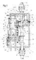
- FIG. 1 shows a section of a folding turret 10, for example, after Requirement of US 4 084 393 - but double lane - is formed.
- the plate-shaped, Folding turret 10 rotating about a vertical axis has two immediately adjacent one another Pockets 11, into which the pack contents are inserted, namely one each Cigarette block 12.
- Blank 13 for wrapping the contents of the pack, namely a block of cigarettes 12.
- the cigarette blocks 12 are successively on a conveyor track 14 in the radial direction transported to the folding turret 10.
- An endless conveyor namely a block conveyor 15, consists of (two) endless belts 16, in particular toothed belts.
- Each belt 16 is via a deflection roller 19 out.
- the two adjacent pulleys sit on one common shaft 20.
- the block conveyor 15 is expedient after In accordance with DE 199 44 780.
- the objects fed by the (block) conveyor 15, namely cigarette blocks 12, are on the plate-shaped conveyor track 14 at a distance from the folding turret 10 positioned.
- the transfer of the cigarette blocks 12 to the folding turret 10 or the insert into the pockets 11 is effected by an insert 21.
- the pusher 21 returns the starting position (Fig. 1, right) back.
- the pusher 21 can be moved by a special gear 22 (EP 0 994 029).
- the (Cycloid) gear 22 has a substantially cylindrical gear housing 23 on. Inside this fixed, outer gear housing 23 is a rotatable Part stored, namely a rotating part 24.
- a crank piece 25 is connected to this in the axis-parallel direction, a rotating arm 26 for actuating the (two) pushers 21 is attached. By rotating the rotating part 24 and additional, superimposed movement the crank piece 25 is the complex movement path of the driver or Inserter 21 causes.
- the block conveyor 15 and the gear 22 are in the present embodiment connected to a common drive, namely to a main shaft 27 or machine shaft. With this there are further gears and conveyors within the machine and other movable organs connected.
- the main shaft 27 is via an angular gear 28 with a drive wheel or a Gear connected, namely a main wheel 29. This sits on a cross to Main shaft 27 directed gear shaft 30. The free, remote from the main gear 29 The end of this gear shaft 30 is via a coupling 31 with the shaft 20 for the drive the block conveyor 15 connected.
- the clutch 31 here consists of two clutch disks 32, 33 by bolts 34 to transmit the torque to each other are connected.
- the main wheel 29 also includes the drive for the slider 21, that is to say for the latter Gear 22 on.
- the main gear 29 is connected to a gear gear 36 via an intermediate gear 35 of the gear 22 connected.
- the gear wheel 36 in turn sits on a gear shaft 37, namely releasably via a coupling, namely clamping coupling 38.
- a drive for a disk shaft 39 is also connected to the gear wheel 36, on which a plurality of cams is attached.
- the cams serve to control other organs that are not shown here.
- the movable organs or gears are lubricated in a special way, namely supplied with oil.
- this topic is based on the Lubricant supply for the transmission 22 shown.
- the gearbox 22 is accommodated in an attachment housing 40, which is part of a partial housing 41 of the machine.
- This essentially consists of parallel housing walls, which in the area of the top housing 40 a continuation or upwards form a directive extension.
- the gears or shafts are rotatably mounted.
- the gear 22 is on the outside Gear housing 23 fixedly arranged in two parallel housing walls.
- a distribution organ is arranged in the top housing 40 or in the partial housing 41 .
- This consists of a distributor plate 42 on the underside of an (upper) housing cover 43 is attached (Fig. 2).
- the distributor element namely the distributor plate 42, has downwardly open bores 44 which serve as distributor openings for the Serve oil.
- the holes 44 are positioned so that, for example, dropwise oil discharged downwards reaches the area to be supplied. The oil is accordingly due to its own weight after leaving the distributor plate 42 the lubrication points fed.
- the holes 44 are dimensioned so that the individually required Oil quantity escapes regularly.
- the bores 44 are supplied with oil continuously or from time to time via a corresponding one Distribution system.
- 42 channels 45 are provided in the distributor plate, in a form and distribution that the necessary oil supply corresponds.
- the channels 45 are upwardly open grooves in the distributor plate 42.
- Seals secured namely by sealing strips 46, which are also in the distributor plate 42 to both Sides of the channels 45 are embedded. The seal is obtained by pressing the Distribution plate 42 to the housing cover 43.
- the distributor plate 42 or the system of the channels 45 is connected to a central oil supply connected.
- a supply line 47 leads from an oil supply to the channels 45 or to one end of the channels 45.
- the feed line 47 is connected to one in the lower region of the Part housing 41 formed oil sump 48 connected. The excess oil is also in these returned from the gears etc.
- the oil sump 48 is the oil over a Oil pump 49 removed and fed to the supply system or the feed line 47. Additional, individual oil lines to each lubrication point are not required.
- gearbox 22 An example of this is the gearbox 22.
- a fixed part and a part to be moved Organ namely the gear housing 23 on the one hand and the rotating part 24 on the other hand, are (mechanically) in a functionally adjusted relative position on the entire machine fixed.
- an easily detachable connecting element here a tab 50, which has transverse plug-in members at the ends, namely pins 51, 52.
- pins 51, 52 These are in bores 53 or depressions of the parts or organs to be connected introduced.
- the bores 53 or depressions are precisely precalculated Position attached so that by inserting the connection or the pins 51, 52 automatically the exact relative position between the parts 23 and 24 is created.
- the gear housing 23 has an edge-side flange 54 provided, in the area of which the bore 53 for the pin 51 is positioned.
- This unit also includes the gear wheel 36 on the gear shaft 37.
- the gear wheel 36 is also fixed in the calculated relative position, specifically on the transmission housing 23.
- a corresponding bore 56 is in the gear wheel 36.
- the holes 55, 56 are brought to cover and a fixing member, namely introduced a pin 57.
- At least one of the cams namely an edge-side cam 58 in a likewise based on calculation determined relative position is fixed, with the result that the fixed on the disc shaft 39 arranged further cams are also positioned accordingly.
- the Cam 58 is provided with a bore 59 into which a pin 60 is inserted becomes. This can from the outside, namely from outside of the partial housing 41, in the plug position to be brought.
- An outer housing wall 61 is in a corresponding position provided with a passage opening 62 for the pin 60.
- the control member having the cam disks is connected to the transmission 22.
- On the disk shaft 39 is a transmission disk on the side facing the transmission 22 63 attached.
- This is via an elastic shown schematically here Coupling connected to the gear wheel 36 of the transmission 22.
- the elastic Coupling is shown symbolically in the present case by plug sleeves 64 and bolts 65.
- the gear wheel 36 thus transmits the drive movement to the gear 22 on the one hand and on the disk shaft 39 on the other.
- the drive for the block conveyor 15 is mounted and adjusted.
- the drive unit for the block conveyor 15 or the clutch 31 is also mechanically fixed in a calculated relative position.
- a pin 67 is inserted, which with a outer traverse 68 is connected.
- a second one connected to the traverse 68 Pin 69 enters a bore 70 in a wall of the sub-housing 41.
- Fig. 8 shows a top view of a packaging machine for the production of Hinged box (cigarette) packs.
- a special feature is that the machine in areas or machine units is divided. These are connected to each other in terms of gear and drive technology, but can with regard to the setting of organs, gears or Machine elements processed independently and then to the overall drive of the machine be connected.
- drive shafts namely the main shaft 27 and with this geared secondary shafts 71, divided into shaft sections 72, 73.
- Each machine unit is connected to one of these shaft sections 72, 73.
- the Shaft sections 72, 73 are connected to one another by couplings 74. These will each for connecting an adjusted machine section to the one already set Part of the machine tightened.
- the procedure is such that from an initial or "0 position" of the folding turret 10 is assumed. Then a first, geared to this Folding turret 10 adjoining machine unit 75 is adjusted in the manner described and fixed.
- the relevant machine unit 75 is connected to a via the auxiliary shaft 71 Main gear 76 connected. After adjusting the machine unit 75, the Coupling 74 of the auxiliary shaft 71 tightened.
- a machine unit 77 then becomes on the output side of the main transmission 76 set. Then the subsequent clutch 74 is tightened between the Shaft sections 72 and 73. Further machine units follow, the machine unit 78 is described in detail above.
- the connecting means for fixing the movable members can be released. Now the entirety of the machine is at a predetermined starting or 0 position aligned. This can be done on a ring scale 79 by turning it accordingly the same are displayed.
- the ring scale 79 is positioned on the main shaft 27 and rotates with it so that during each phase of a machine cycle using the Ring scale 79 track the position of all units, gears and machine elements can be.
- An exact angular position is via a resolver of known design via electrical Signals can be displayed on a screen.
- the resolver 80 is also on the main shaft 27 arranged.
Landscapes
- Engineering & Computer Science (AREA)
- Mechanical Engineering (AREA)
- Wrapping Of Specific Fragile Articles (AREA)
- Manufacturing Of Cigar And Cigarette Tobacco (AREA)
Abstract
Description
- Fig. 1
- einen Ausschnitt einer Verpackungsmaschine für Zigaretten, nämlich im Wesentlichen ein Einschubaggregat, in Seitenansicht bzw. im Vertikalschnitt,
- Fig. 2
- eine Einzelheit eines Getriebegehäuses der Fig. 1 in vergrößertem Maßstab,
- Fig. 3
- einen Horizontalschnitt zu der Einzelheit gemäß Fig. 2 in der Schnittebene III-III,
- Fig. 4
- die Einzelheit gemäß Fig. 1 in Draufsicht bzw. im Horizontalschnitt in der Schnittebene IV-IV der Fig. 1,
- Fig. 5
- einen Teilbereich der Einzelheit gemäß Fig. 4,
- Fig. 6
- eine Seitenansicht bzw. ein Vertikalschnitt des Aggregats gemäß Fig. 1, Fig. 4 und Fig. 5 in der (vertikalen) Schnittebene VI-VI der Fig. 4,
- Fig. 7
- eine weitere Einzelheit der Maschine, nämlich einen Resolver mit einstellbarer Skala in Ansicht,
- Fig. 8
- eine Verpackungsmaschine in vereinfachter Draufsicht mit Einrichtungen zur abschnittweisen Justierung.
- 10
- Faltrevolver
- 11
- Tasche
- 12
- Zigarettenblock
- 13
- Zuschnitt
- 14
- Förderbahn
- 15
- Blockförderer
- 16
- Gurt
- 17
- Mitnehmer
- 18
- Traverse
- 19
- Umlenkrolle
- 20
- Welle
- 21
- Einschieber
- 22
- Getriebe
- 23
- Getriebegehäuse
- 24
- Drehteil
- 25
- Kurbelstück
- 26
- Dreharm
- 27
- Hauptwelle
- 28
- Winkelgetriebe
- 29
- Hauptrad
- 30
- Getriebewelle
- 31
- Kupplung
- 32
- Kupplungsscheibe
- 33
- Kupplungsscheibe
- 34
- Bolzen
- 35
- Zwischenrad
- 36
- Getrieberad
- 37
- Getriebewelle
- 38
- Klemmkupplung
- 39
- Scheibenwelle
- 40
- Aufsatzgehäuse
- 41
- Teilgehäuse
- 42
- Verteilerplatte
- 43
- Gehäuseabdeckung
- 44
- Bohrung
- 45
- Kanal
- 46
- Dichtstreifen
- 47
- Zuführleitung
- 48
- Ölsumpf
- 49
- Ölpumpe
- 50
- Lasche
- 51
- Stift
- 52
- Stift
- 53
- Bohrung
- 54
- Flansch
- 55
- Bohrung
- 56
- Bohrung
- 57
- Stift
- 58
- Kurvenscheibe
- 59
- Bohrung
- 60
- Stift
- 61
- Gehäusewand
- 62
- Durchtrittsöffnung
- 63
- Übertragungsscheibe
- 64
- Steckhülse
- 65
- Bolzen
- 66
- Bohrung
- 67
- Stift
- 68
- Traverse
- 69
- Stift
- 70
- Bohrung
- 71
- Nebenwelle
- 72
- Wellenabschnitt
- 73
- Wellenabschnitt
- 74
- Kupplung
- 75
- Maschineneinheit
- 76
- Hauptgetriebe
- 77
- Maschineneinheit
- 78
- Maschineneinheit
- 79
- Ringskala
- 80
- Resolver
Claims (11)
- Maschine, insbesondere (Zigaretten-)Verpackungsmaschine, mit Aggregaten und Organen, die mindestens während des Betriebs zeitweilig oder ständig mit einem fließfähigen Schmiermittel - Öl - versorgt werden, dadurch gekennzeichnet, dass oberhalb des zu versorgenden Aggregats oder Organs ein Ölverteiler angeordnet ist, dem Öl über eine Zuführleitung (47) zuführbar ist und von dem Öl über Verteileröffnungen ständig oder portionsweise durch Eigengewicht den zu versorgenden Bereichen zuführbar ist.
- Maschine nach Anspruch 1, dadurch gekennzeichnet, dass oberhalb der zu versorgenden Aggregate bzw. Organe eine Verteilerplatte (42) angeordnet ist, die oberhalb der Schmierstellen Durchtrittsöffnungen - Bohrungen (44) - aufweist, denen Öl zuführbar ist und von denen Öl insbesondere tropfenweise nach unten abgegeben wird.
- Maschine nach Anspruch 2, dadurch gekennzeichnet, dass mehrere Bohrungen (44) innerhalb der Verteilerplatte (42) an Kanäle (45) bzw. an ein Kanalsystem angeschlossen sind und dass die Kanäle (45) ihrerseits mit der Zuführleitung (47) verbunden sind.
- Maschine nach Anspruch 2 oder einem der weiteren Ansprüche, dadurch gekennzeichnet, dass die Verteilerplatte (42) mit nach oben offenen, nutartigen Kanälen (45) an der Unterseite eines Teils eines Maschinengestells (40, 41) angebracht ist, insbesondere an einer Gehäuseabdeckung (43), wobei die Kanäle (45) durch beidseits angeordnete Dichtstreifen (46) abgedichtet sind.
- Maschine, insbesondere (Zigaretten-)Verpackungsmaschine, mit bewegbaren Aggregaten und Organen, wie Getrieben, Förderern, Faltrevolvern, Speichern etc., die in einer aufeinander abgestimmten Weise bewegbar sind, gekennzeichnet durch folgende Merkmale:a) zur Montage bzw. zum Zusammenbau der Maschine oder einzelner Getriebe, Aggregate etc. sind hinsichtlich der Bewegung aufeinander abgestimmte Getriebe, Organe, Aggregate, Maschinenelemente etc. durch mechanische Halte- oder Verbindungsmittel in einer vorgegebenen, auf die Gesamtfunktion der Maschine abgestimmten Relativstellung zueinander fixierbar,b) nach der Montage, insbesondere vor der Inbetriebnahme, sind die Halte- oder Verbindungsmittel entfernbar bzw. lösbar.
- Maschine nach Anspruch 5, dadurch gekennzeichnet, dass die bewegbaren Organe, Aggregate, Getriebeteile, Maschinenelemente etc. durch Steckorgane in der vorberechneten Relativstellung fixierbar sind, insbesondere durch Stifte (51, 52; 60; 67, 69), die in Bohrungen (53; 59; 66, 70) einführbar sind.
- Vorrichtung nach Anspruch 6 oder einem der weiteren Ansprüche, dadurch gekennzeichnet, dass Stifte, insbesondere jeweils zwei Stifte (51, 52; 67, 69) miteinander verbunden sind, insbesondere durch Laschen (50) oder Traversen (68), wobei jeweils ein Stift dem feststehenden und der andere Stift dem beweglichen Organ zugeordnet ist.
- Vorrichtung nach Anspruch 5 oder einem der weiteren Ansprüche, dadurch gekennzeichnet, dass drehbare Organe, Maschinenelemente, insbesondere Scheiben, Räder oder dergleichen, Ausnehmungen oder Bohrungen aufweisen, die in exakter Relativstellung mit Ausnehmungen, Bohrungen etc. von feststehenden Maschinenteilen, insbesondere von Gehäusewänden, korrespondieren, derart, dass bei Überdeckung ein Verbindungsorgan, insbesondere ein Stift, in beide Bohrungen, Ausnehmungen oder dergleichen einführbar ist.
- Maschine nach Anspruch 5 oder einem der weiteren Ansprüche, dadurch gekennzeichnet, dass Teile einer Maschine, insbesondere Getriebe (22), Aggregate oder dergleichen, außerhalb der Maschine montierbar und durch mechanische Verbindungsorgane hinsichtlich der Relativstellung fixierbar sind und dass die fixierten Getriebe, Aggregate oder dergleichen als Einheit in die Maschine einsetzbar und durch Kupplungen, insbesondere über Steckverbindungen, mit anderen Organen, Getrieben innerhalb der Maschine positionsgenau verbindbar sind.
- Maschine nach Anspruch 5 oder einem der weiteren Ansprüche, dadurch gekennzeichnet, dass die Maschine bzw. ein Teil derselben in Maschineneinheiten (75, 77, 78) unterteilt ist, wobei die Maschineneinheiten (75, 77, 78) hinsichtlich des Antriebs lösbar über Kupplungen (74) miteinander verbunden sind, derart, dass die Maschineneinheiten (75, 77, 78) nacheinander in funktioneller Reihenfolge hinsichtlich der bewegbaren Organe, Getriebe, Aggregate oder Maschinenelemente justierbar und fixierbar und dass die eingestellten und festgesetzten Maschineneinheiten entsprechend durch Anziehen der Kupplungen (74) an die bereits eingestellten Maschineneinheiten anschließbar sind.
- Maschine nach Anspruch 10 oder einem der weiteren Ansprüche, dadurch gekennzeichnet, dass der bzw. jeder Maschineneinheit (75, 77, 78) ein Wellenabschnitt (72, 73) als Teil der Hauptwelle (27) bzw. einer Nebenwelle (71) zugeordnet ist und dass die Wellenabschnitte (72, 73) über Kupplungen (74) miteinander verbunden sind, derart, dass nach dem Einstellen und Festsetzen der Organe einer Maschineneinheit der zugeordnete Wellenabschnitt (72, 73) mit dem vorangehenden Wellenabschnitt durch Anziehen der Kupplung fest verbindbar ist.
Applications Claiming Priority (2)
| Application Number | Priority Date | Filing Date | Title |
|---|---|---|---|
| DE10020198 | 2000-04-25 | ||
| DE10020198 | 2000-04-25 |
Publications (3)
| Publication Number | Publication Date |
|---|---|
| EP1149769A2 true EP1149769A2 (de) | 2001-10-31 |
| EP1149769A3 EP1149769A3 (de) | 2002-01-16 |
| EP1149769B1 EP1149769B1 (de) | 2004-09-29 |
Family
ID=7639855
Family Applications (1)
| Application Number | Title | Priority Date | Filing Date |
|---|---|---|---|
| EP01108012A Expired - Lifetime EP1149769B1 (de) | 2000-04-25 | 2001-03-29 | Maschine, insbesondere Zigaretten-Verpackungsmaschine |
Country Status (2)
| Country | Link |
|---|---|
| EP (1) | EP1149769B1 (de) |
| DE (1) | DE50103824D1 (de) |
Citations (5)
| Publication number | Priority date | Publication date | Assignee | Title |
|---|---|---|---|---|
| US1885500A (en) | 1931-02-21 | 1932-11-01 | Toledo Machine And Tool Compan | Lubricating system |
| US3078960A (en) | 1961-05-31 | 1963-02-26 | Morpul Inc | Lubricating system for knitting machines and the like |
| US4084393A (en) | 1974-08-21 | 1978-04-18 | Focke & Pfuhl | Apparatus for making and filling hinged boxes of a foldable material |
| US5029672A (en) | 1989-10-13 | 1991-07-09 | Am International | Lubricating system for printing, duplicating and like machines |
| EP0994029A1 (de) | 1998-10-15 | 2000-04-19 | Focke & Co. (GmbH & Co.) | Vorrichtung zur Erzeugung hin- und hergehender Bewegungen |
Family Cites Families (8)
| Publication number | Priority date | Publication date | Assignee | Title |
|---|---|---|---|---|
| DE3909492C1 (de) * | 1989-03-22 | 1990-04-19 | Maschinenfabrik Alfred Schmermund Gmbh & Co, 5820 Gevelsberg, De | |
| IT1262269B (it) * | 1993-04-07 | 1996-06-19 | Sasib Spa | Macchina confezionatrice, in particolare macchina impacchettatrice, di sigarette o simili. |
| IT1281205B1 (it) * | 1995-02-15 | 1998-02-17 | Sasib Spa | Trasportatore angolare per oggetti astiformi delicati o simili, in particolare nelle macchine impacchettatrici di sigarette. |
| IT1281228B1 (it) * | 1995-08-02 | 1998-02-17 | Sasib Spa | Macchina operatrice, in particolare macchina impacchettatrice per sigarette, o simili. |
| IT1288447B1 (it) * | 1996-07-05 | 1998-09-22 | Sasib Spa | Gruppo di azionamento, in particolare nelle macchine operatrici automatiche. |
| DE19706215A1 (de) * | 1997-02-18 | 1998-08-20 | Focke & Co | Verpackungsmaschine, insbesondere für die Fertigung von Zigaretten-Packungen |
| DE19715653A1 (de) * | 1997-04-15 | 1998-10-22 | Focke & Co | Verfahren zum Betrieb von Maschinen mit rotierenden Aggregaten sowie Maschine mit rotierendem Aggregat, insbesondere Verpackungsmaschine mit (Falt-)Revolver |
| IT1305963B1 (it) * | 1998-05-22 | 2001-05-21 | Sasib Tobacco Spa | Macchina operatrice modulare. |
-
2001
- 2001-03-29 DE DE50103824T patent/DE50103824D1/de not_active Expired - Lifetime
- 2001-03-29 EP EP01108012A patent/EP1149769B1/de not_active Expired - Lifetime
Patent Citations (5)
| Publication number | Priority date | Publication date | Assignee | Title |
|---|---|---|---|---|
| US1885500A (en) | 1931-02-21 | 1932-11-01 | Toledo Machine And Tool Compan | Lubricating system |
| US3078960A (en) | 1961-05-31 | 1963-02-26 | Morpul Inc | Lubricating system for knitting machines and the like |
| US4084393A (en) | 1974-08-21 | 1978-04-18 | Focke & Pfuhl | Apparatus for making and filling hinged boxes of a foldable material |
| US5029672A (en) | 1989-10-13 | 1991-07-09 | Am International | Lubricating system for printing, duplicating and like machines |
| EP0994029A1 (de) | 1998-10-15 | 2000-04-19 | Focke & Co. (GmbH & Co.) | Vorrichtung zur Erzeugung hin- und hergehender Bewegungen |
Also Published As
| Publication number | Publication date |
|---|---|
| EP1149769A3 (de) | 2002-01-16 |
| DE50103824D1 (de) | 2004-11-04 |
| EP1149769B1 (de) | 2004-09-29 |
Similar Documents
| Publication | Publication Date | Title |
|---|---|---|
| DE2760217C2 (de) | ||
| WO2008022734A1 (de) | Dosierband | |
| DE3043719C2 (de) | ||
| DE69510040T2 (de) | Überführung vonstabförmigen Artikeln | |
| EP0268917B1 (de) | Verpackungsmaschine, insbesondere für Zigarettenpackungen | |
| DE19605265A1 (de) | Förderlinie für Erzeugnisse | |
| DE19915271A1 (de) | Fördereinrichtung für Gegenstände in Verpackungsmaschinen | |
| DE3301032A1 (de) | Vorrichtung zum herstellen von rueckenbeleimten bloecken | |
| DE69505042T2 (de) | Übertragungsvorrichtung, insbesondere in Zigaretten- Verpackungsmaschinen | |
| DE102010062043B4 (de) | Drehmechanismus für eine Werkzeugmaschine | |
| DE69617558T2 (de) | Verarbeitungsmaschine, insbesondere Verpackungsmaschine für Zigaretten oder dergleichen | |
| DE4224897C1 (de) | ||
| DE4112571C1 (de) | ||
| DE2737442B2 (de) | Stanz-Biegeautomat | |
| EP1149769B1 (de) | Maschine, insbesondere Zigaretten-Verpackungsmaschine | |
| EP0543196B1 (de) | Antriebsanordnung für Deckel-Gummiermaschinen | |
| DE10022284A1 (de) | Maschine, insbesondere (Zigaretten-)Verpackungsmaschine | |
| EP1888392A1 (de) | Elektrisches antriebssystem mit rutschlenkung für ein fahrzeug, getriebeeinheit und fahrzeug | |
| EP1498353A1 (de) | Verpackungsmaschine | |
| DE3245260A1 (de) | Doppelnocken-teilgetriebe | |
| DE69813408T2 (de) | Vorrichtung zum überführen von zigarettenportionen | |
| EP0994818B1 (de) | Verfahren zur einstellung eines kettenförderers in einer behandlungsmaschine | |
| DE3034627C2 (de) | Schrittantriebsvorrichtung | |
| DE1222845C2 (de) | Kartoniermaschine | |
| DE2916794C2 (de) |
Legal Events
| Date | Code | Title | Description |
|---|---|---|---|
| PUAI | Public reference made under article 153(3) epc to a published international application that has entered the european phase |
Free format text: ORIGINAL CODE: 0009012 |
|
| AK | Designated contracting states |
Kind code of ref document: A2 Designated state(s): DE GB IT Kind code of ref document: A2 Designated state(s): AT BE CH CY DE DK ES FI FR GB GR IE IT LI LU MC NL PT SE TR |
|
| AX | Request for extension of the european patent |
Free format text: AL;LT;LV;MK;RO;SI |
|
| PUAL | Search report despatched |
Free format text: ORIGINAL CODE: 0009013 |
|
| AK | Designated contracting states |
Kind code of ref document: A3 Designated state(s): AT BE CH CY DE DK ES FI FR GB GR IE IT LI LU MC NL PT SE TR |
|
| AX | Request for extension of the european patent |
Free format text: AL;LT;LV;MK;RO;SI |
|
| 17P | Request for examination filed |
Effective date: 20020712 |
|
| AKX | Designation fees paid |
Free format text: DE GB IT |
|
| TPAC | Observations by third parties |
Free format text: ORIGINAL CODE: EPIDOSNTIPA |
|
| 17Q | First examination report despatched |
Effective date: 20031007 |
|
| GRAP | Despatch of communication of intention to grant a patent |
Free format text: ORIGINAL CODE: EPIDOSNIGR1 |
|
| RTI1 | Title (correction) |
Free format text: MACHINE, IN PARTICULAR CIGARETTE PACKAGING MACHINE |
|
| GRAS | Grant fee paid |
Free format text: ORIGINAL CODE: EPIDOSNIGR3 |
|
| GRAA | (expected) grant |
Free format text: ORIGINAL CODE: 0009210 |
|
| AK | Designated contracting states |
Kind code of ref document: B1 Designated state(s): DE GB IT |
|
| REG | Reference to a national code |
Ref country code: GB Ref legal event code: FG4D Free format text: NOT ENGLISH |
|
| GBT | Gb: translation of ep patent filed (gb section 77(6)(a)/1977) | ||
| REG | Reference to a national code |
Ref country code: IE Ref legal event code: FG4D Free format text: GERMAN |
|
| REF | Corresponds to: |
Ref document number: 50103824 Country of ref document: DE Date of ref document: 20041104 Kind code of ref document: P |
|
| RAP2 | Party data changed (patent owner data changed or rights of a patent transferred) |
Owner name: FOCKE & CO. (GMBH & CO. KG) |
|
| REG | Reference to a national code |
Ref country code: IE Ref legal event code: FD4D |
|
| PLBE | No opposition filed within time limit |
Free format text: ORIGINAL CODE: 0009261 |
|
| STAA | Information on the status of an ep patent application or granted ep patent |
Free format text: STATUS: NO OPPOSITION FILED WITHIN TIME LIMIT |
|
| 26N | No opposition filed |
Effective date: 20050630 |
|
| PGFP | Annual fee paid to national office [announced via postgrant information from national office to epo] |
Ref country code: GB Payment date: 20150325 Year of fee payment: 15 |
|
| GBPC | Gb: european patent ceased through non-payment of renewal fee |
Effective date: 20160329 |
|
| PG25 | Lapsed in a contracting state [announced via postgrant information from national office to epo] |
Ref country code: GB Free format text: LAPSE BECAUSE OF NON-PAYMENT OF DUE FEES Effective date: 20160329 |
|
| PGFP | Annual fee paid to national office [announced via postgrant information from national office to epo] |
Ref country code: IT Payment date: 20170320 Year of fee payment: 17 |
|
| PGFP | Annual fee paid to national office [announced via postgrant information from national office to epo] |
Ref country code: DE Payment date: 20170331 Year of fee payment: 17 |
|
| REG | Reference to a national code |
Ref country code: DE Ref legal event code: R119 Ref document number: 50103824 Country of ref document: DE |
|
| PG25 | Lapsed in a contracting state [announced via postgrant information from national office to epo] |
Ref country code: DE Free format text: LAPSE BECAUSE OF NON-PAYMENT OF DUE FEES Effective date: 20181002 |
|
| PG25 | Lapsed in a contracting state [announced via postgrant information from national office to epo] |
Ref country code: IT Free format text: LAPSE BECAUSE OF NON-PAYMENT OF DUE FEES Effective date: 20180329 |