EP1148328B2 - Procédé et dispositif d'essai optique de pneus - Google Patents
Procédé et dispositif d'essai optique de pneus Download PDFInfo
- Publication number
- EP1148328B2 EP1148328B2 EP01109655.9A EP01109655A EP1148328B2 EP 1148328 B2 EP1148328 B2 EP 1148328B2 EP 01109655 A EP01109655 A EP 01109655A EP 1148328 B2 EP1148328 B2 EP 1148328B2
- Authority
- EP
- European Patent Office
- Prior art keywords
- tyre
- camera
- light
- sections
- change
- Prior art date
- Legal status (The legal status is an assumption and is not a legal conclusion. Google has not performed a legal analysis and makes no representation as to the accuracy of the status listed.)
- Expired - Lifetime
Links
- 238000000034 method Methods 0.000 title claims description 43
- 238000012360 testing method Methods 0.000 title claims description 37
- 230000003287 optical effect Effects 0.000 title claims description 5
- 238000006073 displacement reaction Methods 0.000 claims description 18
- 238000005259 measurement Methods 0.000 claims description 15
- 238000012545 processing Methods 0.000 claims description 14
- 230000007547 defect Effects 0.000 claims description 12
- 230000006378 damage Effects 0.000 claims description 9
- 238000001514 detection method Methods 0.000 claims description 4
- 230000001681 protective effect Effects 0.000 claims description 4
- 230000001360 synchronised effect Effects 0.000 claims description 4
- 238000005096 rolling process Methods 0.000 claims description 3
- 239000011159 matrix material Substances 0.000 claims 1
- 238000012634 optical imaging Methods 0.000 claims 1
- 230000001105 regulatory effect Effects 0.000 claims 1
- 230000008030 elimination Effects 0.000 description 7
- 238000003379 elimination reaction Methods 0.000 description 7
- 238000010008 shearing Methods 0.000 description 7
- 230000007847 structural defect Effects 0.000 description 6
- 230000005855 radiation Effects 0.000 description 4
- 230000035945 sensitivity Effects 0.000 description 3
- 239000011324 bead Substances 0.000 description 2
- 230000009172 bursting Effects 0.000 description 2
- 230000001427 coherent effect Effects 0.000 description 2
- 208000027418 Wounds and injury Diseases 0.000 description 1
- 230000005856 abnormality Effects 0.000 description 1
- 238000013459 approach Methods 0.000 description 1
- 230000006835 compression Effects 0.000 description 1
- 238000007906 compression Methods 0.000 description 1
- 238000011161 development Methods 0.000 description 1
- 230000018109 developmental process Effects 0.000 description 1
- 238000010586 diagram Methods 0.000 description 1
- 230000000694 effects Effects 0.000 description 1
- 230000006698 induction Effects 0.000 description 1
- 208000014674 injury Diseases 0.000 description 1
- 230000003993 interaction Effects 0.000 description 1
- 239000000463 material Substances 0.000 description 1
- 239000000523 sample Substances 0.000 description 1
- 238000004441 surface measurement Methods 0.000 description 1
- 230000001960 triggered effect Effects 0.000 description 1
Images


Classifications
-
- G—PHYSICS
- G01—MEASURING; TESTING
- G01M—TESTING STATIC OR DYNAMIC BALANCE OF MACHINES OR STRUCTURES; TESTING OF STRUCTURES OR APPARATUS, NOT OTHERWISE PROVIDED FOR
- G01M17/00—Testing of vehicles
- G01M17/007—Wheeled or endless-tracked vehicles
- G01M17/02—Tyres
- G01M17/027—Tyres using light, e.g. infrared, ultraviolet or holographic techniques
Definitions
- compression testing machines are used to test tires, especially before retreading them.
- the tire is inflated from low pressure to high pressure.
- the examiner scans sidewalls and tread with his hands as the tire rotates. If bumps occur indicating damage, they will be detected and the test aborted.
- This procedure involves a high risk of accident and injury to the operator, as the tire may burst during the trial in the event of serious damage to the tire structure before the user has recognized the damaged area and could cancel the test.
- an interferometric method for segmentally testing a tire wherein each test segment is tested at two different internal pressures of the tire.
- the tire is lined with coherent light and before and after a change in the tire inflation pressure with a test head and a calculator an interferogram of the tire surface in the examined test segment generated.
- the generated interferograms are each converted into a modulo 2 ⁇ image, which in turn is processed into a gray value image. From a comparison of the gray value images, information about existing defects of the tire in the examined test segment is obtained. Thereafter, the tire is rotated further the amount of a test segment and the test repeated at the two different internal pressures of the tire for the next test segment.
- the patent EP 0 823 623 B1 presents an interferometric method for testing tires in which the tire is irradiated with coherent light and the radiation scattered back from the tire is split into two partial radiations.
- the two partial radiations are brought together again in such a way that the two partial radiations are slightly offset relative to one another (shearing).
- the Shearing module used is adjusted so that the shear direction is radially aligned with the tire. Since the presented measuring method works interferometrically, the measurement must be carried out in such a way that is checked sector by sector, in each case the tire pressure must be changed for each sector. However, the required pressure change is very low due to the very high sensitivity.
- the continuous measurement along a baseline has the advantage that it can be carried out very quickly.
- the disadvantage is that only a very small section of the surface is checked. If a defect has a greater distance to the said baseline, it will not affect the baseline, or only slightly, and thus remain undetected. Further, the tire will expand both in the transverse direction and in the radial direction due to the pressure increase, so that the base line shifts with respect to the tire surface when the sensors on the testing machine are rigidly fastened. Due to discontinuities on the tire surface, e.g. in the form of flow seams, lettering reliefs, etc., it can then lead to interference signals in the measurement, which are then incorrectly classified as structural defects.
- the proposed interferometric method has the disadvantage that the sensitivity of the shearing module is determined solely by shear direction and shear angle and not by the surface shape.
- the elongation during shearing is measured with respect to the distance of the pixels corresponding to the shear angle and not with respect to the true distance of the imaged surface points, so that the sensitivity as a function of the distance of the object with respect to the shearing module and depending on the inclination of the surface with respect to the observation direction varies greatly.
- the DE 198 49 793 C1 describes a triangulation method for non-contact detection of unevenness of a tire sidewall, in which a camera captures the tire sidewall onto which light slices are projected.
- the tire is rotated about its roll axis to obtain a three-dimensional representation of the surface from which the curvature of the surface is extracted and existing edges, which occur, for example, at the edge of characters, are smoothed.
- Remaining bumps are interpreted as bumps and, if they exceed a threshold, are displayed as errors.
- the change in shape of the tire due to the change in the tire pressure is detected by projecting light cuts on the surface of the tire, which are detected by a camera with flat image sensor.
- the camera is preferably a video camera with a CCD chip. It is sufficient to project only one light section, but several light sections can be projected simultaneously.
- the tire is rotated with respect to the camera and thus simultaneously with respect to the means for projecting the light cuts.
- the roll axis of the tire is preferably used.
- the recording of the light sections through the camera is performed according to the invention at defined rotational positions of the tire relative to the camera. Thus, various portions of the tire surface are sequentially detected.
- the defined rotational positions ensure that the measurements of different tire pressures can be compared later.
- the tire is advantageously continuously rotated relative to the camera and the light cuts taken by the camera at a speed in relation to the rotational speed of short exposure time.
- the camera is advantageously equipped with a mechanical or electronic shutter.
- the image recording of the camera via a suitable device, such as an induction switch, synchronized with the rotational movement of the tire relative to the camera to obtain the light cuts at defined rotational positions.
- the three-dimensional shape of the light sections is determined by triangulation by the image processing system. From the three-dimensional shape of the light sections, the three-dimensional shape of the tire is determined. If necessary, existing gaps can be closed by interpolation and filters can be applied to the measured data in order to clean them up.
- the contour measurement is repeated at different pressures and the measured shape shapes of the tire surface are compared at different tire pressures. For this purpose, the light sections of each identical rotational positions of the tire are advantageously used at different tire pressures.
- the pressure change is preferably carried out in such a way that the tire pressure is gradually increased from a low initial pressure either continuously or between the contour measurements.
- the change in shape tangential and orthogonal to the tire surface can be studied exactly. It can always be assumed that the tire bead or the rim flange does not appreciably deform due to the pressure change. If, according to one aspect of the invention, the tire shoulder and the side surface of the tire are detected, a determination of the diameter change is also possible. For this purpose, in particular the geometrically striking corner region of the tire shoulder is suitable. According to another aspect of the invention, the change in shape of the tire due to the pressure change may also be decomposed into its axial and radial components with respect to the rolling axis of the tire.
- the strain change perpendicular to the computational component in the considered contour lines is computationally eliminated.
- the radial strain change and for the calculation of the radial displacements the axial strain change is eliminated.
- This procedure is particularly advantageous when the side wall and / or the tread of the tire has a pronounced surface relief. This is practically always the case on the side surface because of the usual lettering reliefs and on the tread because of the profile.
- the elimination of the radial or axial expansion avoids that the displacement of the surface relief perpendicular to the examined displacement direction leads to local discontinuities in the deformation behavior.
- the data from adjacent cross sections can also be used to avoid incorrect decisions.
- the search for structural defects is advantageously carried out continuously while the test is running. If a defect is discovered, the overpressure in the tire is advantageously immediately reduced in order to prevent the tire from bursting.
- several, eg two, light-section systems are advantageously used. These are arranged to each other so that the light section systems do not interfere with each other during simultaneous operation. For this purpose, it is necessary that the generated light surfaces and light sections of the other light-section systems are not visible to the cameras.
- the individual light-section systems are arranged offset to the tire circumference, for example. With such a system, serious defects are definitely detected in time, so that the test can be stopped before the tire bursts.
- the shape of the tire surface is also examined as such and not only the deformation behavior determined by comparing two or more surface contours.
- This procedure makes it possible to locate defects in shape, in particular damage to the tire sidewall in the form of material breakouts, grooves, etc.
- the actual geometry can be compared with a desired geometry or searched for levels whose height exceeds a certain threshold.
- the measured surface of the tire is examined at a low initial pressure at the beginning of the test run for shape error back and finding the heavier damage the actual pressure test no longer stirred.
- the presence of the tire contour can be used advantageously to inform the operator of the location and size of the defects found on the tire during the test.
- the results are displayed, for example, as a polar diagram or clear details of the tire surface are calculated.
- the FIG. 1 shows a simplified schematic representation of an apparatus for testing tires according to an embodiment of the invention.
- the tire 1 is mounted on a rim 2 and rotatably mounted about the axis 3 with respect to the test stand 4 about its roll axis.
- a compressed air supply 13 with a compressed air regulator 14 the tire pressure can be varied even with rotating tires.
- the test system has a light-section system fixedly connected to the test stand 4 via the holder 7, consisting of a camera 8 and a device 11 for the projection of light sections.
- the camera 8 may be a commercially available video camera.
- the device 11 for the projection of light sections consists for example of a laser scanner or a laser whose beam is expanded by means of a cylindrical lens.
- the image data taken by the camera 8 are transmitted to an image processing system 12 for further processing.
- the image acquisition of the camera 8 is also triggered by a trigger signal from the image processing system 12.
- the axle 3 is driven by the motor 15 and rotates the tire during the constant speed measurement.
- an index mark 5 which is detected by the sensor 6.
- the signal generated when passing the index mark 5 on the sensor 6 is used by the image processing system 12 as a synchronization pulse.
- the camera 8 is synchronized only once per axis rotation with the rotational movement and otherwise runs free.
- the defined rotational positions are determined by the time frame of the image recording of the camera 8 and the rotational speed of the final drive.
- This approach is sufficiently accurate, since the timing of modern video cameras is extremely accurate.
- the camera 8 is equipped according to one aspect of the invention with an anamorphic optics 9, in which the image scales in the image plane in the horizontal and vertical directions are different are.
- the magnifications are independently chosen so that on the one hand in the radial direction side wall and tire shoulder are completely detected and that on the other hand, the resolution in the Triangulationsebene is as large as possible.
- the camera is housed in a protective housing 10.
- a protective housing is advantageously also attached to the device 11.
- the light-sectioning system is oriented so that the device 11 generates light cuts which cut the sidewall of the tire 1 in the radial direction and extend beyond the tire shoulder into the tread area.
- the camera 8 is simultaneously aligned so that the projected light section on both the sidewall and in the shoulder region of the tire 1 is completely detected.
- the light slit plane is projected obliquely through the device 11 onto the sidewall of the tire.
- the tire 1 is rotated about the axis 3 at a frequency of about 0.5 Hz.
- 50 light sections can be detected on the circumference.
- the number of light cuts is correspondingly higher. If a video camera operating in interlaced mode is used and each field is exposed separately, this number can be doubled, with the number of picture lines and thus the number of measuring points per picture being halved.
- FIG. 2 shows that in FIG. 1 illustrated test system in plan view.
- the triangulation angle between the optical axes of the device 11 and the camera 8 can be recognized.
- FIG. 3 shows the position of the light sections in the measurement of the tire sidewall with the in FIG. 1 and FIG. 2 shown test system.
- the drawn 50 light cuts L1 to L50 are generated or measured at a rotational frequency of the tire of 0.5 Hz and an image recording frequency of 25 Hz.
- the contour lines L1 to L50 are obtained at a distance of 7.2 ° each.
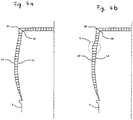
- the FIG. 4a shows the change of a contour line when increasing the tire pressure.
- the contour line L1 corresponds to a low pressure, the contour line L1 'to a higher pressure.
- the outermost point of the tire shoulder S1 shifts to the point S1 '. Since the tire shoulder is geometrically clearly defined, the total expansion of the contour line can be calculated from the displacement S 1 ⁇ S 1 ', inter alia.
- the strains can be determined very accurately because all the reference lengths can be present or determined in true size.
- the FIG. 4b shows the behavior of the tire when pressure is increased, if there is a structural defect.
- the contour line L2 corresponds to a low pressure, the contour line L2 'to a higher pressure.
- the marked area D there is a defect leading to a local bulge in this area.
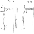
- FIG. 5a schematically shows the procedure in the calculation of the pure axial displacements with elimination of the radial strain change.
- the contour line L1 is measured at a low initial pressure and shows a pronounced surface relief in both the sidewall and the tread.
- the contour line L1 ' is measured.
- the corners of the surface relief shift both in the radial and in the axial direction.
- first of all the elongation of the contour line L1 'with respect to the contour line L 1 in the radial direction is determined and then mathematically eliminated.
- the shape change behavior along the contour line L1 in the axial direction is subsequently determined by point-by-point determination of the axial distance of the contour lines L1 and L1 ".
- the determination of the radial strain change can be determined, for example, by calculating the radial displacement of the Schultereckiss S 1. All displacements are advantageously measured with respect to the detected points of the rim 2.
- the extension of the contour line L1 'with respect to the contour line L 1 in the radial direction is calculated from the distances FS1 and FS1'.
- FIG. 5b schematically shows the procedure in the calculation of the pure radial displacements with elimination of the axial strain.
- first of all the elongation of the contour line L1 'with respect to the contour line L 1 in the axial direction is determined and subsequently eliminated mathematically. This results in the contour line L1 '''.
- the shape change behavior along the contour line L1 in the radial direction is then determined by comparing the contour lines L1 and L1 '''.
Claims (40)
- Procédé d'essai de pneumatiques (1), selon lequel on modifie la pression intérieure du pneu (1), on mesure la déformation du pneu provoquée par cette modification de la pression intérieure et on détermine, à partir de la déformation mesurée, des caractéristiques et/ou des défauts de structure du pneu, le procédé comprenant les étapes consistant à projeter au moins une coupe optique sur la surface du pneu, à observer à l'aide d'une caméra (8) la coupe optique projetée, à tourner le pneu par rapport à la caméra (8) pour obtenir plusieurs coupes optiques, à réaliser l'enregistrement des coupes optiques projetées, à l'aide de la caméra (8), pour des positions angulaires définies du pneu par rapport à la caméra, à envoyer à un système de traitement d'images (12) les images des coupes optiques projetées enregistrées, à déterminer la forme des coupes optiques grâce à une triangulation effectuée par le système de traitement d'images (12), à déterminer la forme de la surface du pneu à partir de la forme des coupes optiques, à répéter la mesure de la forme de la surface du pneu pour des pressions différentes du pneu, et à déterminer la déformation du pneu, suite à la modification de la pression intérieure, en comparant les formes de la surface du pneu pour des pressions de pneu différentes.
- Procédé selon la revendication 1, caractérisé par le fait que le pneu est tourné autour de son axe de roulement par rapport à la caméra.
- Procédé selon la revendication 1 ou 2, caractérisé par le fait que pour déterminer la déformation du pneu, on utilise les coupes optiques mesurées dé positions angulaires identiques du pneu pour des pressions différentes du pneu.
- Procédé selon les revendications 1 à 3, caractérisé par le fait que la pression du pneu est augmentée en continu.
- Procédé selon les revendications 1 à 3, caractérisé par le fait que la pression du pneu est augmentée par paliers et la forme du pneu est de nouveau mesurée pour une pression de pneu constante, chaque fois qu'un nouveau palier de pression est atteint.
- Procédé selon les revendications 1 à 5, caractérisé par le fait que le pneu est tourné en plusieurs pas par rapport à la caméra et l'enregistrement des coupes optiques projetées sur le pneu est effectué chaque fois entre les différents mouvements de rotation.
- Procédé selon les revendications 1 à 5, caractérisé par le fait que le pneu exécute un mouvement rotatoire continu par rapport à la caméra.
- Procédé selon la revendication 7, caractérisé par le fait que le pneu est tourné à une vitesse constante par rapport à la caméra.
- Procédé selon la revendication 7 ou 8, caractérisé par le fait que la prise de vues de la caméra est synchronisée avec le mouvement rotatoire du pneu par rapport à la caméra.
- Procédé selon la revendication 9, caractérisé par le fait que la prise de vues de la caméra est synchronisée avec le mouvement rotatoire du pneu uniquement pour une position angulaire sélectionnée, et les positions angulaires suivantes sont définies par la trame de temps ou la fréquence d'images de la caméra.
- Procédé selon les revendications 7 à 10, caractérisé par le fait que la caméra travaille avec des trames qui sont exposées de façon décalée dans le temps.
- Procédé selon les revendications 1 à 11, caractérisé par le fait que les surfaces optiques produisant les coupes optiques sont des plans.
- Procédé selon la revendication 12, caractérisé par le fait que les plans de coupe optique produits sont orientés de manière telle que des coupes optiques s'étendant radialement de l'intérieur vers l'extérieur soient projetées sur la surface latérale du pneu.
- Procédé selon la revendication 12 ou 13, caractérisé par le fait que les coupes optiques projetées sont reproduites sur le détecteur d'image de la caméra de manière telle que la résolution d'image qui est perpendiculaire aux plans de coupe optique soit supérieure à celle qui leur est parallèle.
- Procédé selon les revendications 1 à 14, caractérisé par le fait que la paroi latérale du pneu et l'épaulement de pneu contigu sont enregistrés en même temps.
- Procédé selon les revendications 1 à 15, caractérisé par le fait que les surfaces latérales opposées du pneu sont contrôlées en parallèle, en utilisant simultanément plusieurs systèmes de coupe optique.
- Procédé selon les revendications 1 à 16, caractérisé par le fait que la déformation est déterminée point par point à partir des distances des coupes de surface pour des pressions de pneu différentes, perpendiculairement à la surface du pneu.
- Procédé selon les revendications 1 à 17, caractérisé par le fait que les dilatations de la surface du pneu sont calculées à partir des longueurs et des variations de longueur des coupes de surface.
- Procédé selon les revendications 1 à 18, caractérisé par le fait que pour déterminer le comportement de déformation, on calcule point par point les déplacements des coupes de surface pour des pressions de pneu différentes, dans la direction axiale et/ou radiale par rapport à l'axe de roulement du pneu.
- Procédé selon la revendication 19, caractérisé par le fait que pour calculer les déplacements axiaux de la surface du pneu suite à une modification de pression, on élimine par le calcul les variations de dilatation existant dans la direction radiale dans les coupes de surface utilisées pour le calcul des déplacements axiaux.
- Procédé selon la revendication 19, caractérisé par le fait que pour calculer les déplacements radiaux de la surface du pneu suite à une modification de pression, on élimine par le calcul les variations de dilatation existant dans la direction axiale dan les coupes de surface utilisées pour le calcul des déplacements radiaux.
- Procédé selon les revendications 1 à 21, caractérisé par le fait que pendant que l'essai est en cours, le système de traitement d'images recherche en continu et de façon automatique des défauts structurels.
- Procédé selon la revendication 22, caractérisé par le fait qu'immédiatement après avoir détecté un défaut structurel, le système de traitement d'images réduit la surpression régnant dans le pneu et interrompt l'essai.
- Procédé selon les revendications 1 à 23, caractérisé par le fait que la surface de pneu enregistrée est examinée pour détecter des défauts de forme extérieurs, en particulier des détériorations.
- Procédé selon la revendication 24, caractérisé par le fait qu'avant de commencer l'augmentation de pression, la surface du pneu est examinée pour détecter des défauts de forme extérieurs.
- Procédé selon les revendications 1 à 25, caractérisé par le fait que les résultats de l'essai sont représentés dans un système de coordonnées commun.
- Système d'essai de pneumatiques (1) comprenant
un dispositif (2) de réception du pneu (1),
une alimentation en air comprimé (13)
un dispositif (14) pour modifier la pression du pneu ;
caractérisé par
au moins un système de coupe optique qui comprend
au moins un dispositif (11) pour projeter des coupes optiques sur le pneu (1), qui est en état de produire des surfaces optiques plans qui sont orientés de manière telle que les coupe optiques s'étendant radialement de l'intérieur vers l'extérieur soient projetées au moins sur la surface latérale du pneu (1), et
une caméra (8) pour observer les coupes optiques projetées sur le pneu (1) ;
un dispositif (4) avec un axe de rotation (3) permettant de faire tourner le pneu (1) par rapport au dispositif (11) de génération de surfaces optiques et par rapport à la caméra (8) ;
un système de traitement d'images (12) qui exploite les images enregistrées par la caméra (8) ;
des moyens pour produire, enregistrer et traiter des coupes optiques projetées ;
des moyens pour déterminer le contour de surface tridimensionnel du pneu ;
des moyens pour déterminer le contour de surface tridimensionnel pour des pressions de pneu différentes ;
des moyens pour déterminer la déformation du pneu (1) en cas de changement de la pression de pneu ; et
des moyens pour déterminer des caractéristiques et/ou des défauts de structure du pneu (1). - Système selon la revendication 27, caractérisé par le fait que l'optique de reproduction de la caméra (8) comprend une optique anamorphotique (9).
- Système selon les revendications 27 à 28, caractérisé par le fait que la caméra (8) est équipée d'un obturateur mécanique ou électronique.
- Système selon les revendications 27 à 29, caractérisé par le fait que la caméra (8) fonctionne selon le procédé d'entrelacement et avec des trames exposées de façon décalée dans le temps.
- Système selon les revendications 27 à 30, caractérisé par le fait que le dispositif (11) de projection de coupes optiques est constitué d'un projecteur muni d'un réseau optique.
- Système selon les revendications 27 à 30, caractérisé par le fait que le dispositif (11) de projection de coupes optiques est constitué d'un ou plusieurs scanners au laser.
- Système selon les revendications 27 à 30, caractérisé par le fait que le dispositif (11) de projection de coupes optiques est constitué d'un ou plusieurs lasers à optique d'étalage de faisceau.
- Système selon les revendications 27 à 33, caractérisé par le fait que le système d'essai présente un détecteur (6) pour détecter au moins une marque de repère (5) placée sur l'axe de rotation (3) et le détecteur (6) envoie un signal de synchronisation au système de traitement d'images (12) et/ou à la caméra (8).
- Système selon les revendications 27 à 34, caractérisé par le fait que la caméra (8) présente un moyen de protection (10) qui protège la caméra (8) contre des détériorations provoquées par l'éclatement d'un pneu.
- Système selon les revendications 27 à 35, caractérisé par le fait que le dispositif (11) de projection de coupes optiques présente un moyen de protection qui protège le dispositif (11) contre des détériorations provoquées par l'éclatement d'un pneu.
- Système selon les revendications 27 à 36, caractérisé par le fait que le dispositif (14) de réglage de la pression de pneu présente un moyen de commande qui est activé par le système de traitement d'images (12).
- Système selon les revendications 27 à 37, caractérisé par le fait que l'axe (3) pour tourner le pneu (1) par rapport à la caméra (8) et par rapport au dispositif (11) de projection de coupes optiques est entraîné par moteur.
- Système selon la revendication 38, caractérisé par le fait que le moyen d'entraînement de l'axe (3) est activé par l'intermédiaire du système de traitement d'images (12).
- Système selon les revendications 27 à 39, caractérisé par le fait que le système d'essai présente deux ou plus de deux systèmes de coupe optique qui enregistrent en parallèle les surfaces latérales opposées du pneu.
Applications Claiming Priority (2)
| Application Number | Priority Date | Filing Date | Title |
|---|---|---|---|
| DE10019386A DE10019386C2 (de) | 2000-04-19 | 2000-04-19 | Verfahren und Vorrichtung zur Prüfung von Reifen |
| DE10019386 | 2000-04-19 |
Publications (4)
| Publication Number | Publication Date |
|---|---|
| EP1148328A2 EP1148328A2 (fr) | 2001-10-24 |
| EP1148328A3 EP1148328A3 (fr) | 2003-12-17 |
| EP1148328B1 EP1148328B1 (fr) | 2005-11-23 |
| EP1148328B2 true EP1148328B2 (fr) | 2016-12-28 |
Family
ID=7639305
Family Applications (1)
| Application Number | Title | Priority Date | Filing Date |
|---|---|---|---|
| EP01109655.9A Expired - Lifetime EP1148328B2 (fr) | 2000-04-19 | 2001-04-19 | Procédé et dispositif d'essai optique de pneus |
Country Status (3)
| Country | Link |
|---|---|
| US (1) | US6615650B2 (fr) |
| EP (1) | EP1148328B2 (fr) |
| DE (2) | DE10019386C2 (fr) |
Families Citing this family (52)
| Publication number | Priority date | Publication date | Assignee | Title |
|---|---|---|---|---|
| US6326613B1 (en) | 1998-01-07 | 2001-12-04 | Donnelly Corporation | Vehicle interior mirror assembly adapted for containing a rain sensor |
| US6124886A (en) | 1997-08-25 | 2000-09-26 | Donnelly Corporation | Modular rearview mirror assembly |
| US6278377B1 (en) | 1999-08-25 | 2001-08-21 | Donnelly Corporation | Indicator for vehicle accessory |
| US6445287B1 (en) | 2000-02-28 | 2002-09-03 | Donnelly Corporation | Tire inflation assistance monitoring system |
| US8288711B2 (en) | 1998-01-07 | 2012-10-16 | Donnelly Corporation | Interior rearview mirror system with forwardly-viewing camera and a control |
| US6420975B1 (en) | 1999-08-25 | 2002-07-16 | Donnelly Corporation | Interior rearview mirror sound processing system |
| US7480149B2 (en) | 2004-08-18 | 2009-01-20 | Donnelly Corporation | Accessory module for vehicle |
| WO2001064481A2 (fr) | 2000-03-02 | 2001-09-07 | Donnelly Corporation | Systeme de miroir video integrant un module accessoire |
| US6396408B2 (en) | 2000-03-31 | 2002-05-28 | Donnelly Corporation | Digital electrochromic circuit with a vehicle network |
| JP4363506B2 (ja) * | 2000-08-10 | 2009-11-11 | 横浜ゴム株式会社 | 空気入りタイヤのトレッド摩耗量測定方法 |
| JP2003220811A (ja) * | 2002-01-30 | 2003-08-05 | Sumitomo Rubber Ind Ltd | タイヤ空気圧低下検出方法および装置、ならびにタイヤ減圧判定のプログラム |
| WO2003065084A1 (fr) | 2002-01-31 | 2003-08-07 | Donnelly Corporation | Module d'accessoires de vehicule |
| DE602004029642D1 (de) * | 2003-11-25 | 2010-12-02 | Sumitomo Rubber Ind | Verfahren und Gerät zum Detektieren eines Druckabfalls in Reifen, und Programm für die Beurteilung eines Druckabfalls in Reifen |
| US7269997B2 (en) | 2004-06-03 | 2007-09-18 | Snap-On Incorporated | Non-contact method and system for tire analysis |
| DE102004050355A1 (de) | 2004-10-15 | 2006-04-27 | Steinbichler Optotechnik Gmbh | Verfahren und Vorrichtung zum Prüfen der Oberfläche eines Reifens |
| WO2006063827A1 (fr) | 2004-12-15 | 2006-06-22 | Magna Donnelly Electronics Naas Limited | Systeme module accessoire pour fenetre d'un vehicule |
| DE102004062412B4 (de) * | 2004-12-23 | 2007-02-01 | Mähner, Bernward | Verfahren zur räumlichen Vermessung sich schnell bewegender Objekte |
| DE502006009454D1 (de) * | 2006-03-23 | 2011-06-16 | Bernward Maehner | Ewegender objekte |
| DE102006015123B4 (de) * | 2006-03-31 | 2008-03-20 | Mähner, Bernward | Vorrichtung und Verfahren zum Prüfen eines Reifens, insbesondere mittels eines interferometrischen Messverfahrens |
| JP4977415B2 (ja) * | 2006-07-21 | 2012-07-18 | 株式会社ブリヂストン | タイヤ検査用基準形状データの作成装置および作成方法 |
| US7677077B2 (en) * | 2006-12-21 | 2010-03-16 | The Goodyear Tire & Rubber Company | Sensor calibration device and method for a tire |
| US8087301B2 (en) * | 2007-09-24 | 2012-01-03 | Infineon Technologies Ag | Optical systems and methods for determining tire characteristics |
| DE102007056967B4 (de) | 2007-11-27 | 2009-09-17 | Mähner, Bernward | Verfahren und Vorrichtung zur Herstellung formtreuer Reifen |
| DE102007062105B4 (de) | 2007-12-21 | 2011-06-22 | Mähner, Bernward, 82205 | Vorrichtung und Verfahren zur Prüfung und räumlichen Vermessung sich drehender Objekte, insbesondere von Reifen |
| EP2110656B1 (fr) * | 2008-04-14 | 2011-07-06 | Snap-on Equipment Srl a unico socio | Appareil pour déterminer l'état d'un ensemble de roue |
| DE102008037356C5 (de) | 2008-08-12 | 2020-09-17 | Bernward Mähner | Stapelmodul und Zentriermodul für eine Prüfanlage zum Prüfen von Reifen |
| US7805987B1 (en) * | 2008-08-19 | 2010-10-05 | Smith Bradley R | System and method for pneumatic tire defect detection |
| US8570374B2 (en) | 2008-11-13 | 2013-10-29 | Magna Electronics Inc. | Camera for vehicle |
| DE102009008468B4 (de) | 2009-02-15 | 2017-08-31 | Bernward Mähner | Verfahren zur Prüfung von Reifen |
| DE102009008470A1 (de) | 2009-02-15 | 2010-08-26 | Mähner, Bernward | Verfahren und Vorrichtung zur räumlichen Vermessung eines sich bewegenden Objektes |
| IT1394907B1 (it) * | 2009-07-22 | 2012-07-20 | Bridgestone Corp | Metodo ed impianto di ricostruzione di un pneumatico |
| WO2011065938A1 (fr) * | 2009-11-24 | 2011-06-03 | Michelin Recherche Et Technique, S.A. | Test sur véhicule de la résistance d'un pneu à une agression latérale |
| DE102010006105A1 (de) * | 2010-01-28 | 2011-08-18 | Siemens Aktiengesellschaft, 80333 | Vorrichtung und Verfahren zur sequentiellen Musterprojektion |
| JP5562278B2 (ja) * | 2011-03-15 | 2014-07-30 | 株式会社神戸製鋼所 | タイヤ形状検査装置、及びタイヤ形状検査方法 |
| DE102011076068A1 (de) * | 2011-05-18 | 2012-11-22 | Bayerische Motoren Werke Aktiengesellschaft | Verfahren und Vorrichtung zur Fahrzeugrad-Kontrolle |
| US9511633B2 (en) | 2011-08-17 | 2016-12-06 | Deere & Company | Soil compaction management and reporting |
| US8843269B2 (en) * | 2011-08-17 | 2014-09-23 | Deere & Company | Vehicle soil pressure management based on topography |
| ITMI20112253A1 (it) * | 2011-12-13 | 2013-06-14 | Pirelli | Metodo per controllare la deposizione di semilavorati elementari in un processo di confezione di pneumatici per ruote di veicoli |
| US9805697B1 (en) | 2012-06-01 | 2017-10-31 | Hunter Engineering Company | Method for tire tread depth modeling and image annotation |
| MX352132B (es) * | 2012-11-15 | 2017-11-08 | Android Ind Llc | Sistema y método para determinar la uniformidad de un neumático.. |
| DE102013102296B4 (de) | 2012-12-21 | 2018-11-08 | Bernward Mähner | Vorrichtung und Verfahren zum Prüfen eines Reifens mittels eines interferometrischen Messverfahrens |
| DE102013104004A1 (de) * | 2013-04-19 | 2014-10-23 | Schoen + Sandt Machinery Gmbh | Prüfvorrichtung und -Verfahren |
| EP3087366B1 (fr) * | 2013-12-23 | 2020-05-06 | Pirelli Tyre S.p.A. | Procédé et appareil pour détecter les défauts sur les pneus dans un processus de production de pneus |
| US10636227B2 (en) | 2014-06-19 | 2020-04-28 | The Goodyear Tire & Rubber Company | System and method for multiple feature detection and analysis of a rotating tire |
| CN104527337A (zh) * | 2014-12-01 | 2015-04-22 | 深圳市元征科技股份有限公司 | 一种轮胎胎压的检测方法、装置及移动设备和照相设备 |
| US10697858B2 (en) | 2015-12-16 | 2020-06-30 | Pirelli Tyre S.P.A. | Method and device for checking tyres |
| CN107848348A (zh) * | 2016-06-30 | 2018-03-27 | 华为技术有限公司 | 一种爆胎预警方法及装置 |
| IT201700016046A1 (it) | 2017-02-14 | 2018-08-14 | Tekna Automazione E Controllo S R L | Apparato per il rilevamento e la verifica di difetti superficiali di un pneumatico al termine di un processo di produzione |
| WO2018229805A1 (fr) * | 2017-06-12 | 2018-12-20 | Pirelli Tyre S.P.A. | Procédé pour contrôler des pneus |
| US11112239B1 (en) | 2017-11-10 | 2021-09-07 | Hunter Engineering Company | Method for tire shoulder tread wear evaluation |
| CN111238834A (zh) * | 2020-01-20 | 2020-06-05 | 东莞市秉能橡胶有限公司 | 一种轮胎测量方法 |
| CN113945163A (zh) * | 2021-09-07 | 2022-01-18 | 通力轮胎有限公司 | 一种充气式轮胎断面扫描装置及方法 |
Family Cites Families (9)
| Publication number | Priority date | Publication date | Assignee | Title |
|---|---|---|---|---|
| US4745469A (en) * | 1987-02-18 | 1988-05-17 | Perceptron, Inc. | Vehicle wheel alignment apparatus and method |
| US5313827A (en) * | 1992-09-28 | 1994-05-24 | The Goodyear Tire & Rubber Company | Method and apparatus for detecting ply defects in pneumatic tires |
| US5703680A (en) * | 1996-01-16 | 1997-12-30 | The Goodyear Tire & Rubber Company | Method for dynamic interference pattern testing |
| GB2314928B (en) * | 1996-07-04 | 2001-02-14 | Sun Electric Uk Ltd | Tyre condition assessment |
| ES2188696T3 (es) * | 1996-08-06 | 2003-07-01 | Nova C O R D Ag | Procedimiento para detectar los defectos de los neumaticos. |
| AU6294398A (en) * | 1997-02-03 | 1998-08-25 | Joachim Burger | Method and device for measuring the pattern depth on a tyre |
| US5987978A (en) * | 1997-04-02 | 1999-11-23 | Assembly Technology & Test Ltd. | Apparatus for testing tire tread depth |
| DE19731486C2 (de) * | 1997-07-22 | 2001-02-22 | Beissbarth Gmbh | Reifenprüfvorrichtung |
| DE19849793C1 (de) * | 1998-10-28 | 2000-03-16 | Fraunhofer Ges Forschung | Vorrichtung und Verfahren zur berührungslosen Erfassung von Unebenheiten in einer gewölbten Oberfläche |
-
2000
- 2000-04-19 DE DE10019386A patent/DE10019386C2/de not_active Expired - Fee Related
-
2001
- 2001-04-19 DE DE50108131T patent/DE50108131D1/de not_active Expired - Lifetime
- 2001-04-19 EP EP01109655.9A patent/EP1148328B2/fr not_active Expired - Lifetime
- 2001-08-13 US US09/927,336 patent/US6615650B2/en not_active Expired - Fee Related
Also Published As
| Publication number | Publication date |
|---|---|
| EP1148328A3 (fr) | 2003-12-17 |
| DE50108131D1 (de) | 2005-12-29 |
| DE10019386C2 (de) | 2003-04-03 |
| US6615650B2 (en) | 2003-09-09 |
| US20010052259A1 (en) | 2001-12-20 |
| EP1148328A2 (fr) | 2001-10-24 |
| DE10019386A1 (de) | 2001-10-31 |
| EP1148328B1 (fr) | 2005-11-23 |
Similar Documents
| Publication | Publication Date | Title |
|---|---|---|
| EP1148328B2 (fr) | Procédé et dispositif d'essai optique de pneus | |
| DE19849793C1 (de) | Vorrichtung und Verfahren zur berührungslosen Erfassung von Unebenheiten in einer gewölbten Oberfläche | |
| EP1332334B2 (fr) | Dispositif de mesure servant a effectuer des mesures sans contact sur des pneumatiques | |
| DE102006014070B4 (de) | Vorrichtung und Verfahren zum Prüfen eines Reifens, insbesondere mittels eines interferometrischen Messverfahrens | |
| EP1647817B1 (fr) | Méthode et dispositif pour test optique de surface de roue | |
| DE4231578C2 (de) | Verfahren zur Ermittlung von Verformungen an einem Prüfobjekt mit diffus streuender Oberfläche, insbesondere an Reifen, sowie Vorrichtung zur Durchführung des Verfahrens | |
| EP2002235B1 (fr) | Dispositif et procede de controle d'un pneumatique, en particulier au moyen d'une mesure interferometrique | |
| DE19809790B4 (de) | Verfahren zur Ermittlung einer Drallstruktur in der Oberfläche eines feinbearbeiteten zylindrischen Werkstücks | |
| DE10333802B4 (de) | Verfahren und Vorrichtung zum Prüfen von Reifen | |
| EP1959227A2 (fr) | Dispositif et procédé destinés à la vérification d'un pneu, en particulier à l'aide d'un procédé de mesure interférométrique | |
| WO1999004248A1 (fr) | Procede de detection automatique de defauts superficiels au niveau de carrosseries brutes et dispositif permettant de mettre ledit procede en oeuvre | |
| EP3545259B1 (fr) | Procédé et dispositif d'analyse d'objets de test à symétrie de révolution | |
| DE10023172A1 (de) | Vorrichtung und Verfahren zur Messung der Dicke und Unrundheit von länglichen Werkstücken | |
| EP1775548B1 (fr) | Procédé et dispositif pour la détection de la déformation d'objets. | |
| EP1999447B1 (fr) | Dispositif et procédé de contrôle d'un pneu | |
| CN110017784A (zh) | 一种卷曲钢卷端部在线质检装置和方法 | |
| EP0884574B1 (fr) | Procédé et dispositif d'essai de pneus | |
| EP0884560B1 (fr) | Procédé et dispositif de contrôle des pneus | |
| DE10019387C2 (de) | Verfahren und Vorrichtung zur Untersuchung von Reifen | |
| DE102009008468B4 (de) | Verfahren zur Prüfung von Reifen | |
| DE10009870C2 (de) | Verfahren und Vorrichtung zur Untersuchung von Prüfobjekten | |
| DE102019121662A1 (de) | Verfahren zur Prüfung eines Reifens |
Legal Events
| Date | Code | Title | Description |
|---|---|---|---|
| PUAI | Public reference made under article 153(3) epc to a published international application that has entered the european phase |
Free format text: ORIGINAL CODE: 0009012 |
|
| AK | Designated contracting states |
Kind code of ref document: A2 Designated state(s): AT BE CH CY DE DK ES FI FR GB GR IE IT LI LU MC NL PT SE TR |
|
| AX | Request for extension of the european patent |
Free format text: AL;LT;LV;MK;RO;SI |
|
| RAP1 | Party data changed (applicant data changed or rights of an application transferred) |
Owner name: MAEHNER, BERNWARD Owner name: DENGLER, STEFAN |
|
| PUAL | Search report despatched |
Free format text: ORIGINAL CODE: 0009013 |
|
| AK | Designated contracting states |
Kind code of ref document: A3 Designated state(s): AT BE CH CY DE DK ES FI FR GB GR IE IT LI LU MC NL PT SE TR |
|
| AX | Request for extension of the european patent |
Extension state: AL LT LV MK RO SI |
|
| 17P | Request for examination filed |
Effective date: 20040616 |
|
| AKX | Designation fees paid |
Designated state(s): DE FR IT |
|
| 17Q | First examination report despatched |
Effective date: 20041018 |
|
| GRAP | Despatch of communication of intention to grant a patent |
Free format text: ORIGINAL CODE: EPIDOSNIGR1 |
|
| GRAS | Grant fee paid |
Free format text: ORIGINAL CODE: EPIDOSNIGR3 |
|
| GRAA | (expected) grant |
Free format text: ORIGINAL CODE: 0009210 |
|
| AK | Designated contracting states |
Kind code of ref document: B1 Designated state(s): DE FR IT |
|
| REF | Corresponds to: |
Ref document number: 50108131 Country of ref document: DE Date of ref document: 20051229 Kind code of ref document: P |
|
| ET | Fr: translation filed | ||
| PLBI | Opposition filed |
Free format text: ORIGINAL CODE: 0009260 |
|
| PLAX | Notice of opposition and request to file observation + time limit sent |
Free format text: ORIGINAL CODE: EPIDOSNOBS2 |
|
| 26 | Opposition filed |
Opponent name: STEINBICHLER OPTOTECHNIK GMBH Effective date: 20060822 |
|
| PLBB | Reply of patent proprietor to notice(s) of opposition received |
Free format text: ORIGINAL CODE: EPIDOSNOBS3 |
|
| PLAS | Information related to reply of patent proprietor to notice(s) of opposition deleted |
Free format text: ORIGINAL CODE: EPIDOSDOBS3 |
|
| PLBB | Reply of patent proprietor to notice(s) of opposition received |
Free format text: ORIGINAL CODE: EPIDOSNOBS3 |
|
| PLAY | Examination report in opposition despatched + time limit |
Free format text: ORIGINAL CODE: EPIDOSNORE2 |
|
| PLAH | Information related to despatch of examination report in opposition + time limit modified |
Free format text: ORIGINAL CODE: EPIDOSCORE2 |
|
| PLBC | Reply to examination report in opposition received |
Free format text: ORIGINAL CODE: EPIDOSNORE3 |
|
| PLAB | Opposition data, opponent's data or that of the opponent's representative modified |
Free format text: ORIGINAL CODE: 0009299OPPO |
|
| PLAZ | Examination of admissibility of opposition: despatch of communication + time limit |
Free format text: ORIGINAL CODE: EPIDOSNOPE2 |
|
| PLBA | Examination of admissibility of opposition: reply received |
Free format text: ORIGINAL CODE: EPIDOSNOPE4 |
|
| APBM | Appeal reference recorded |
Free format text: ORIGINAL CODE: EPIDOSNREFNO |
|
| APBP | Date of receipt of notice of appeal recorded |
Free format text: ORIGINAL CODE: EPIDOSNNOA2O |
|
| APAH | Appeal reference modified |
Free format text: ORIGINAL CODE: EPIDOSCREFNO |
|
| APBQ | Date of receipt of statement of grounds of appeal recorded |
Free format text: ORIGINAL CODE: EPIDOSNNOA3O |
|
| PGFP | Annual fee paid to national office [announced via postgrant information from national office to epo] |
Ref country code: IT Payment date: 20140428 Year of fee payment: 14 Ref country code: DE Payment date: 20140424 Year of fee payment: 14 Ref country code: FR Payment date: 20140416 Year of fee payment: 14 |
|
| REG | Reference to a national code |
Ref country code: DE Ref legal event code: R119 Ref document number: 50108131 Country of ref document: DE |
|
| PG25 | Lapsed in a contracting state [announced via postgrant information from national office to epo] |
Ref country code: DE Free format text: LAPSE BECAUSE OF NON-PAYMENT OF DUE FEES Effective date: 20151103 Ref country code: IT Free format text: LAPSE BECAUSE OF NON-PAYMENT OF DUE FEES Effective date: 20150419 |
|
| REG | Reference to a national code |
Ref country code: FR Ref legal event code: ST Effective date: 20151231 |
|
| PG25 | Lapsed in a contracting state [announced via postgrant information from national office to epo] |
Ref country code: FR Free format text: LAPSE BECAUSE OF NON-PAYMENT OF DUE FEES Effective date: 20150430 |
|
| APBU | Appeal procedure closed |
Free format text: ORIGINAL CODE: EPIDOSNNOA9O |
|
| PUAH | Patent maintained in amended form |
Free format text: ORIGINAL CODE: 0009272 |
|
| STAA | Information on the status of an ep patent application or granted ep patent |
Free format text: STATUS: PATENT MAINTAINED AS AMENDED |
|
| 27A | Patent maintained in amended form |
Effective date: 20161228 |
|
| AK | Designated contracting states |
Kind code of ref document: B2 Designated state(s): DE FR IT |
|
| REG | Reference to a national code |
Ref country code: DE Ref legal event code: R102 Ref document number: 50108131 Country of ref document: DE |