EP1148262A1 - Linearwälzlager - Google Patents
Linearwälzlager Download PDFInfo
- Publication number
- EP1148262A1 EP1148262A1 EP01106624A EP01106624A EP1148262A1 EP 1148262 A1 EP1148262 A1 EP 1148262A1 EP 01106624 A EP01106624 A EP 01106624A EP 01106624 A EP01106624 A EP 01106624A EP 1148262 A1 EP1148262 A1 EP 1148262A1
- Authority
- EP
- European Patent Office
- Prior art keywords
- filler
- support body
- deflecting
- bearing according
- balls
- Prior art date
- Legal status (The legal status is an assumption and is not a legal conclusion. Google has not performed a legal analysis and makes no representation as to the accuracy of the status listed.)
- Granted
Links
- 238000005096 rolling process Methods 0.000 title claims 2
- 239000000945 filler Substances 0.000 claims description 36
- 239000000463 material Substances 0.000 claims description 8
- 239000012778 molding material Substances 0.000 claims description 6
- 239000000956 alloy Substances 0.000 claims description 4
- 229910045601 alloy Inorganic materials 0.000 claims description 4
- 229910000831 Steel Inorganic materials 0.000 claims description 3
- 239000010959 steel Substances 0.000 claims description 3
- 238000006073 displacement reaction Methods 0.000 description 2
- XAGFODPZIPBFFR-UHFFFAOYSA-N aluminium Chemical compound [Al] XAGFODPZIPBFFR-UHFFFAOYSA-N 0.000 description 1
- 229910052782 aluminium Inorganic materials 0.000 description 1
- 238000004512 die casting Methods 0.000 description 1
- 230000000694 effects Effects 0.000 description 1
- 238000001125 extrusion Methods 0.000 description 1
- 230000037431 insertion Effects 0.000 description 1
- 238000003780 insertion Methods 0.000 description 1
- 238000004519 manufacturing process Methods 0.000 description 1
Images


Classifications
-
- F—MECHANICAL ENGINEERING; LIGHTING; HEATING; WEAPONS; BLASTING
- F16—ENGINEERING ELEMENTS AND UNITS; GENERAL MEASURES FOR PRODUCING AND MAINTAINING EFFECTIVE FUNCTIONING OF MACHINES OR INSTALLATIONS; THERMAL INSULATION IN GENERAL
- F16C—SHAFTS; FLEXIBLE SHAFTS; ELEMENTS OR CRANKSHAFT MECHANISMS; ROTARY BODIES OTHER THAN GEARING ELEMENTS; BEARINGS
- F16C29/00—Bearings for parts moving only linearly
- F16C29/04—Ball or roller bearings
- F16C29/06—Ball or roller bearings in which the rolling bodies circulate partly without carrying load
- F16C29/0633—Ball or roller bearings in which the rolling bodies circulate partly without carrying load with a bearing body defining a U-shaped carriage, i.e. surrounding a guide rail or track on three sides
- F16C29/0635—Ball or roller bearings in which the rolling bodies circulate partly without carrying load with a bearing body defining a U-shaped carriage, i.e. surrounding a guide rail or track on three sides whereby the return paths are provided as bores in a main body of the U-shaped carriage, e.g. the main body of the U-shaped carriage is a single part with end caps provided at each end
- F16C29/0638—Ball or roller bearings in which the rolling bodies circulate partly without carrying load with a bearing body defining a U-shaped carriage, i.e. surrounding a guide rail or track on three sides whereby the return paths are provided as bores in a main body of the U-shaped carriage, e.g. the main body of the U-shaped carriage is a single part with end caps provided at each end with balls
- F16C29/064—Ball or roller bearings in which the rolling bodies circulate partly without carrying load with a bearing body defining a U-shaped carriage, i.e. surrounding a guide rail or track on three sides whereby the return paths are provided as bores in a main body of the U-shaped carriage, e.g. the main body of the U-shaped carriage is a single part with end caps provided at each end with balls with two rows of balls, one on each side of the rail
Definitions
- the invention relates to a linear roller bearing with a guide rail and these surrounding carriages, which over rows of balls on the
- the guide rail is supported in a longitudinally displaceable manner and contains a supporting body, in which for each row of balls one on the length of the support body extending filler provided with a linear ball track which is complete except for the area of the ball track is surrounded by the material of the support body, the rows of Balls in the carriage are parts of endless ball revolutions and the roller bearing two attached to the front of the support body in the directions of displacement Pointing deflecting body with deflecting channels for each ball circulation contains, and with return channels arranged in the support body for the balls, and also one of the filler pieces at the front ends two protruding into the deflecting body, delimiting the deflecting channels Deflection pieces are arranged.
- a linear roller bearing is known from publication EP 0 558 761 B1 which is suitable for two rows of balls a common thin ball plate with two load ball grooves contains.
- the ball plate is in the molding material of the support body Carriage so embedded that the ball grooves on one of the Free surface of the ball plate facing away from the molding material. Therefore here the balls are not held in the guide carriage if it is is detached from the guide rail. The balls then fall out of the ball grooves the ball plate and thus out of the carriage.
- this version has the disadvantage of high hardening costs.
- the invention is based on the object of an inexpensive, easily assembled To create linear roller bearings with non-cutting components, in which the balls are held securely in the carriage even when it is not pushed onto the guide rail.
- the respective filler is divided into two parts along a central parting line.
- This can one filler half each, to which the deflection piece is already attached, simply installed on the support body by plugging in at the end become.
- the support body can each one of the ball groove of the filler adjacent Have channel for supporting balls, which to the guide rail towards a slot of the support body with a compared to the ball diameter smaller width is open. In this way, the filler and the channel completely located in the carriage. The balls are thereby held in the material of the carriage and only protrude through the slot to the guide rail.
- the support body can be made of a molding material such as plastic or die-casting alloy be formed while the two parts of the filler from one hard material such as steel can be formed.
- the two parts of the filler piece can be used as track bars or as track tubes be trained.
- Each deflection piece can be used as a semicircular deflection disc be formed and have a plug that fits into an end Recess of a filler part is inserted appropriately.
- the deflection bodies can also be made of a molding material such as plastic or die-cast alloy. You can screw on the Carrier be attached. But it is also possible to use snap devices to attach to the support body.
- the linear roller bearing according to the invention can be designed such that, apart from the profiled filler piece, all other parts consist of the molding material.
- the filler piece which is designed as a raceway tube or track rod, can each be produced as a drawn part made of steel.
- the production of a tube with a ball track is less expensive than that of a corresponding rod.
- the solution according to the invention enables simple assembly of the individual parts, which can be arranged in a simple manner centered on one another.
- the deflection disks can be plugged into the tubular parts of the filler in a simple manner with the molded plug-in pins. It is therefore only necessary to produce one type of filler half.
- the support body of the carriage can also be made of aluminum by extrusion.
- a guide rail 1 partially surrounded by a carriage 2. This is supported by balls 3 two endless ball revolutions on the two long sides of the guide rail 1 from.
- the carriage 2 consists essentially of a central support body 4 and two arranged on its two end faces deflection bodies 5. According Figure 2 are the two deflecting body 5 with screws 6 on the support body 4 releasably attached. According to Figure 6, the support body 4 and the adjacent deflection body 5 common snap devices 7, with which the deflection body 5 is releasably attached to the support body 4.
- the Assembly is simplified compared to the embodiment according to FIG. 2, in that the Deflection body 5 only to be pressed against the support body 4 takes until the snap devices 7 take effect.
- the supporting body 4 and the deflecting body 5 consist of a molded material, in which the balls are embedded. So the support body 4 as Filling pieces two raceway tubes 8 with ball raceways 9 for loadbearing balls 3 on.
- the raceway tubes 8 are therefore on both sides of the guide rail 1 embedded in the support body 4. The balls 3 can thus both on raceways the guide rail 1 and on the ball raceways 9 of the raceway tubes 8 unroll.
- the ball races 9 into deflection channels 10, which within the Deflector 5 are arranged.
- the balls are in these deflection channels 10 3 from the respective ball track 9 into an associated return channel 11 of the support body 4 initiated.
- the balls 3 roll on the ball tracks 9 along to the respective end of the support body 4 and from there via the deflection channels 10 into the associated return channels 11, then through this and over the deflection channels 10 of the other Deflection body 5 back into the ball raceways 9 of the support body 4.
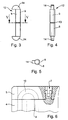
- the raceway tube 8 is designed as a two-part filler 12, which in the Center has a parting line 13. At the two longitudinal ends of the filler 12 border two semicircular deflection disks 14 on the raceway tube 8 on. Each deflection disk 14 delimits the associated deflection channel 10 within of the adjacent deflecting body 5. It is shown in FIGS associated half of the raceway tube 8 permanently connected.
- the two-part filler 15 according to Figures 7 and 8 consists of a lengthwise its parting line 13 divided raceway bar 16, which front recesses 17 has.
- the semicircular deflection plates 14 molded plug 18 provided that fit into the recesses 17th are plugged in. This is a releasable connection between each part of the Filler 15 and the associated deflection plate 14 created.
- connection is also suitable for the two parts of the as a raceway tube 8 trained filler 12 and the associated deflection plates 14, as shown in FIGS. 9 and 10.
- plug 19 of the respective Deflection plate 14 inserted into the raceway tube 8.
Landscapes
- Engineering & Computer Science (AREA)
- General Engineering & Computer Science (AREA)
- Mechanical Engineering (AREA)
- Bearings For Parts Moving Linearly (AREA)
Abstract
Description
Zwei solche Hälften lassen sich in einfacher Weise an den beiden Stirnseiten des Tragkörpers in diesen einstecken und bilden dann gemeinsam ein eingebautes Füllstück. Entsprechendes gilt für stabförmige Füllstückhälften mit angebrachten Umlenkscheiben. Der Tragkörper des Führungswagens kann auch aus Aluminium durch Strangpressen hergestellt werden.
- Figur 1
- ein erfindungsgemäßes Linearwälzlager in einem Quer- schnitt gemäß Linie I-I der Figur 2;
- Figur 2
- den Führungswagen des Linearwälzlagers nach Figur 1 in der Draufsicht;
- Figur 3
- ein als Laufbahnrohr ausgebildetes Füllstück in der Drauf- sicht;
- Figur 4
- das Füllstück nach Figur 3 in der Seitenansicht;
- Figur 5
- ein Teil des Füllstücks in einer stirnseitigen Ansicht gemäß Linie V-V der Figur 3;
- Figur 6
- einen vergrößerten Ausschnitt aus einem gegenüber Figur 2 abgewandelten Führungswagen;
- Figur 7
- ein als Laufbahnstab ausgebildetes Füllstück in der Drauf- sicht;
- Figur 8
- das Füllstück nach Figur 7 in einem Querschnitt gemäß Li- nie VIII-VIII der Figur 7;
- Figur 9
- eine Teildarstellung eines weiteren als Laufbahnrohr aus- gebildeten Füllstücks;
- Figur 10
- einen Querschnitt durch das Füllstück gemäß Linie X-X der Figur 9.
- 1
- Führungsschiene
- 2
- Führungswagen
- 3
- Kugel
- 4
- Tragkörper
- 5
- Umlenkkörper
- 6
- Schraube
- 7
- Schnappvorrichtung
- 8
- Laufbahnrohr
- 9
- Kugellaufbahn
- 10
- Umlenkkanal
- 11
- Rücklaufkanal
- 12
- Füllstück
- 13
- Trennfuge
- 14
- Umlenkscheibe
- 15
- Füllstück
- 16
- Laufbahnstab
- 17
- Ausnehmung
- 18
- Steckzapfen
- 19
- Steckzapfen
Claims (9)
- Linearwälzlager mit einer Führungsschiene (1) und einem diese umgebenden Führungswagen (2), welcher über Reihen von Kugeln (3) an der Führungsschiene (1) längsverschieblich abgestützt ist und einen Tragkörper (4) enthält, in welchem für jede Kugelreihe ein auf der Länge des Tragkörpers (4) sich erstreckendes, mit einer geradlinigen Kugellaufbahn (9) versehenes Füllstück (12, 15) angeordnet ist, welches mit Ausnahme des Bereichs der Kugellaufbahn (9) vollständig von dem Werkstoff des Tragkörpers (4) umgeben ist, wobei die Reihen von Kugeln (3) in dem Führungswagen (2) Teile von endlosen Kugelumläufen sind und das Wälzlager zwei an dem Tragkörper (4) stirnseitig befestigte, in die Verschiebungsrichtungen weisende Umlenkkörper (5) mit Umlenkkanälen (10) für jeden Kugelumlauf enthält, und mit in dem Tragkörper (4) angeordneten Rücklaufkanälen (11) für die Kugeln (3), wobei ferner an den stirnseitigen Enden jeweils eines der Füllstücke (12, 15) zwei in die Umlenkkörper (5) hineinragende, die Umlenkkanäle (10) begrenzende Umlenkstücke angeordnet sind, dadurch gekennzeichnet, dass das jeweilige Füllstück (12, 15) längs einer mittleren Trennfuge (13) in zwei Teile aufgeteilt ist.
- Lager nach Anspruch 1, dadurch gekennzeichnet, dass der Tragkörper (4) jeweils einen der Kugelrille jedes Füllstücks (12, 15) benachbarten Kanal für tragende Kugeln (3) aufweist, welcher zu der Führungsschiene (1) hin über einen Schlitz des Tragkörpers (4) mit einer gegenüber dem Kugeldurchmesser geringeren Breite geöffnet ist.
- Lager nach Anspruch 1, dadurch gekennzeichnet, dass der Tragkörper (4) aus einem Formwerkstoff wie Kunststoff oder Druckgußlegierung gebildet ist, während die beiden Teile des Füllstücks (12, 15) aus einem harten Werkstoff wie Stahl gebildet sind.
- Lager nach Anspruch 1, dadurch gekennzeichnet, dass die beiden Teile des Füllstücks (15) als Laufbahnstäbe (16) ausgebildet sind.
- Lager nach Anspruch 1, dadurch gekennzeichnet, dass die beiden Teile des Füllstücks (12) als Laufbahnrohre (8) ausgebildet sind.
- Lager nach Anspruch 1, dadurch gekennzeichnet, dass jedes Umlenkstück als halbkreisförmige Umlenkscheibe (14) ausgebildet ist und einen Steckzapfen (18, 19) aufweist, der in eine stirnseitige Ausnehmung (17) eines Füllstückteils passend eingesteckt ist.
- Lager nach Anspruch 1 dadurch gekennzeichnet, dass die Umlenkkörper (5) aus einem Formwerkstoff wie Kunststoff oder Druckgußlegierung gebildet sind.
- Lager nach Anspruch 1 dadurch gekennzeichnet, dass die Umlenkkörper (5) mit Schrauben (6) an dem Tragkörper (4) befestigt sind.
- Lager nach Anspruch 1 dadurch gekennzeichnet, dass die Umlenkkörper (5) mit Schnappvorrichtungen (7) an dem Tragkörper (4) befestigt sind.
Applications Claiming Priority (4)
| Application Number | Priority Date | Filing Date | Title |
|---|---|---|---|
| DE10020115 | 2000-04-22 | ||
| DE10020115 | 2000-04-22 | ||
| DE10106038A DE10106038A1 (de) | 2000-04-22 | 2001-02-09 | Linearwälzlager |
| DE10106038 | 2001-02-09 |
Publications (2)
| Publication Number | Publication Date |
|---|---|
| EP1148262A1 true EP1148262A1 (de) | 2001-10-24 |
| EP1148262B1 EP1148262B1 (de) | 2004-08-04 |
Family
ID=26005447
Family Applications (1)
| Application Number | Title | Priority Date | Filing Date |
|---|---|---|---|
| EP20010106624 Expired - Lifetime EP1148262B1 (de) | 2000-04-22 | 2001-03-16 | Linearwälzlager |
Country Status (2)
| Country | Link |
|---|---|
| EP (1) | EP1148262B1 (de) |
| ES (1) | ES2223668T3 (de) |
Citations (7)
| Publication number | Priority date | Publication date | Assignee | Title |
|---|---|---|---|---|
| FR1037175A (fr) * | 1951-05-17 | 1953-09-15 | Etude L I B Soc D | Roulement plat sans fin |
| DE3533403A1 (de) * | 1985-09-19 | 1987-03-26 | Skf Linearsysteme Gmbh | Waelzlager fuer laengsbewegungen |
| FR2612580A1 (fr) * | 1987-03-20 | 1988-09-23 | Teramachi Hiroshi | Paliers coulissants lineaires a contact angulaire |
| FR2615917A1 (fr) * | 1987-05-25 | 1988-12-02 | Teramachi Hiroshi | Palier utilisable a la fois pour des deplacements rectilignes et curvilignes |
| EP0353396A1 (de) * | 1988-07-16 | 1990-02-07 | Werner Jacob | Linearführung |
| US5106206A (en) * | 1991-01-30 | 1992-04-21 | Nippon Thompson Co., Ltd. | Linear motion guide unit manufactured from a resin |
| DE9313728U1 (de) * | 1992-09-10 | 1993-11-25 | Star Gmbh | Wälzlager für Linearbewegungen |
-
2001
- 2001-03-16 ES ES01106624T patent/ES2223668T3/es not_active Expired - Lifetime
- 2001-03-16 EP EP20010106624 patent/EP1148262B1/de not_active Expired - Lifetime
Patent Citations (7)
| Publication number | Priority date | Publication date | Assignee | Title |
|---|---|---|---|---|
| FR1037175A (fr) * | 1951-05-17 | 1953-09-15 | Etude L I B Soc D | Roulement plat sans fin |
| DE3533403A1 (de) * | 1985-09-19 | 1987-03-26 | Skf Linearsysteme Gmbh | Waelzlager fuer laengsbewegungen |
| FR2612580A1 (fr) * | 1987-03-20 | 1988-09-23 | Teramachi Hiroshi | Paliers coulissants lineaires a contact angulaire |
| FR2615917A1 (fr) * | 1987-05-25 | 1988-12-02 | Teramachi Hiroshi | Palier utilisable a la fois pour des deplacements rectilignes et curvilignes |
| EP0353396A1 (de) * | 1988-07-16 | 1990-02-07 | Werner Jacob | Linearführung |
| US5106206A (en) * | 1991-01-30 | 1992-04-21 | Nippon Thompson Co., Ltd. | Linear motion guide unit manufactured from a resin |
| DE9313728U1 (de) * | 1992-09-10 | 1993-11-25 | Star Gmbh | Wälzlager für Linearbewegungen |
Also Published As
| Publication number | Publication date |
|---|---|
| ES2223668T3 (es) | 2005-03-01 |
| EP1148262B1 (de) | 2004-08-04 |
Similar Documents
| Publication | Publication Date | Title |
|---|---|---|
| DE3304783C2 (de) | ||
| DE3005579A1 (de) | Lineare kugellagereinheit | |
| DD248850B5 (de) | Waelzlager fuer Linearbewegungen | |
| DE10109505A1 (de) | Walzenspindel und Walzenspindel-Walzenanordnungsverfahren | |
| EP0802337B1 (de) | Linearwälzlager | |
| DE3311857C2 (de) | Linearlager | |
| DE19815525A1 (de) | Linearführung mit zwangsgeführtem Käfig | |
| DE1812375B1 (de) | Kugellager fuer relative Laengsbewegung auf einer Welle | |
| DE3620571A1 (de) | Waelzlager fuer linearbewegungen | |
| DE19815526A1 (de) | Linearführung mit Zwangsführung des Käfigs | |
| EP1619401A1 (de) | Linearführungseinheit | |
| DE3419450C2 (de) | ||
| WO2004036072A1 (de) | Linearführungseinheit | |
| DE3607633C2 (de) | Umlaufkugellager für Längsverschiebungen | |
| DE4209824A1 (de) | Waelzlager fuer linearbewegungen | |
| EP1148262B1 (de) | Linearwälzlager | |
| DE4439804A1 (de) | Spieleinstellbares Linearlager | |
| DE9011413U1 (de) | Linearantrieb | |
| EP1953401B1 (de) | Führungswagen für Profilschienenführungen | |
| DE3505786A1 (de) | Fuehrung, insbesondere fuer ausziehbare moebelteile | |
| DE10101054A1 (de) | Halteteilaufbau | |
| EP1387098B1 (de) | Linearwälzlager | |
| DE10106038A1 (de) | Linearwälzlager | |
| DE19614513B4 (de) | Linearwälzlager mit einer U-förmigen Führungsschiene | |
| DE3224282A1 (de) | Linearkugellagereinheit |
Legal Events
| Date | Code | Title | Description |
|---|---|---|---|
| PUAI | Public reference made under article 153(3) epc to a published international application that has entered the european phase |
Free format text: ORIGINAL CODE: 0009012 |
|
| 17P | Request for examination filed |
Effective date: 20010316 |
|
| AK | Designated contracting states |
Kind code of ref document: A1 Designated state(s): AT BE CH CY DE DK ES FI FR GB GR IE IT LI LU MC NL PT SE TR Kind code of ref document: A1 Designated state(s): CH DE ES FR IT LI |
|
| AX | Request for extension of the european patent |
Free format text: AL;LT;LV;MK;RO;SI |
|
| AKX | Designation fees paid |
Free format text: CH DE ES FR IT LI |
|
| RAP1 | Party data changed (applicant data changed or rights of an application transferred) |
Owner name: INA-SCHAEFFLER KG |
|
| GRAP | Despatch of communication of intention to grant a patent |
Free format text: ORIGINAL CODE: EPIDOSNIGR1 |
|
| GRAS | Grant fee paid |
Free format text: ORIGINAL CODE: EPIDOSNIGR3 |
|
| GRAA | (expected) grant |
Free format text: ORIGINAL CODE: 0009210 |
|
| AK | Designated contracting states |
Kind code of ref document: B1 Designated state(s): CH DE ES FR IT LI |
|
| REG | Reference to a national code |
Ref country code: CH Ref legal event code: EP |
|
| REG | Reference to a national code |
Ref country code: CH Ref legal event code: NV Representative=s name: TROESCH SCHEIDEGGER WERNER AG |
|
| REF | Corresponds to: |
Ref document number: 50103063 Country of ref document: DE Date of ref document: 20040909 Kind code of ref document: P |
|
| REG | Reference to a national code |
Ref country code: ES Ref legal event code: FG2A Ref document number: 2223668 Country of ref document: ES Kind code of ref document: T3 |
|
| PLBE | No opposition filed within time limit |
Free format text: ORIGINAL CODE: 0009261 |
|
| STAA | Information on the status of an ep patent application or granted ep patent |
Free format text: STATUS: NO OPPOSITION FILED WITHIN TIME LIMIT |
|
| ET | Fr: translation filed | ||
| 26N | No opposition filed |
Effective date: 20050506 |
|
| REG | Reference to a national code |
Ref country code: FR Ref legal event code: CD |
|
| PGFP | Annual fee paid to national office [announced via postgrant information from national office to epo] |
Ref country code: ES Payment date: 20070417 Year of fee payment: 7 |
|
| PGFP | Annual fee paid to national office [announced via postgrant information from national office to epo] |
Ref country code: IT Payment date: 20070514 Year of fee payment: 7 |
|
| PGFP | Annual fee paid to national office [announced via postgrant information from national office to epo] |
Ref country code: CH Payment date: 20080313 Year of fee payment: 8 Ref country code: FR Payment date: 20070308 Year of fee payment: 7 |
|
| REG | Reference to a national code |
Ref country code: FR Ref legal event code: ST Effective date: 20081125 |
|
| PG25 | Lapsed in a contracting state [announced via postgrant information from national office to epo] |
Ref country code: FR Free format text: LAPSE BECAUSE OF NON-PAYMENT OF DUE FEES Effective date: 20080331 |
|
| REG | Reference to a national code |
Ref country code: ES Ref legal event code: FD2A Effective date: 20080317 |
|
| PG25 | Lapsed in a contracting state [announced via postgrant information from national office to epo] |
Ref country code: ES Free format text: LAPSE BECAUSE OF NON-PAYMENT OF DUE FEES Effective date: 20080317 |
|
| PG25 | Lapsed in a contracting state [announced via postgrant information from national office to epo] |
Ref country code: IT Free format text: LAPSE BECAUSE OF NON-PAYMENT OF DUE FEES Effective date: 20080316 |
|
| REG | Reference to a national code |
Ref country code: CH Ref legal event code: PL |
|
| PG25 | Lapsed in a contracting state [announced via postgrant information from national office to epo] |
Ref country code: LI Free format text: LAPSE BECAUSE OF NON-PAYMENT OF DUE FEES Effective date: 20090331 Ref country code: CH Free format text: LAPSE BECAUSE OF NON-PAYMENT OF DUE FEES Effective date: 20090331 |
|
| REG | Reference to a national code |
Ref country code: DE Ref legal event code: R081 Ref document number: 50103063 Country of ref document: DE Owner name: SCHAEFFLER TECHNOLOGIES AG & CO. KG, DE Free format text: FORMER OWNER: SCHAEFFLER TECHNOLOGIES GMBH & CO. KG, 91074 HERZOGENAURACH, DE Effective date: 20120828 Ref country code: DE Ref legal event code: R081 Ref document number: 50103063 Country of ref document: DE Owner name: SCHAEFFLER TECHNOLOGIES GMBH & CO. KG, DE Free format text: FORMER OWNER: SCHAEFFLER TECHNOLOGIES GMBH & CO. KG, 91074 HERZOGENAURACH, DE Effective date: 20120828 |
|
| REG | Reference to a national code |
Ref country code: DE Ref legal event code: R081 Ref document number: 50103063 Country of ref document: DE Owner name: SCHAEFFLER TECHNOLOGIES GMBH & CO. KG, DE Free format text: FORMER OWNER: SCHAEFFLER TECHNOLOGIES AG & CO. KG, 91074 HERZOGENAURACH, DE Effective date: 20140218 Ref country code: DE Ref legal event code: R081 Ref document number: 50103063 Country of ref document: DE Owner name: SCHAEFFLER TECHNOLOGIES AG & CO. KG, DE Free format text: FORMER OWNER: SCHAEFFLER TECHNOLOGIES AG & CO. KG, 91074 HERZOGENAURACH, DE Effective date: 20140218 |
|
| REG | Reference to a national code |
Ref country code: DE Ref legal event code: R081 Ref document number: 50103063 Country of ref document: DE Owner name: SCHAEFFLER TECHNOLOGIES AG & CO. KG, DE Free format text: FORMER OWNER: SCHAEFFLER TECHNOLOGIES GMBH & CO. KG, 91074 HERZOGENAURACH, DE Effective date: 20150210 |
|
| PGFP | Annual fee paid to national office [announced via postgrant information from national office to epo] |
Ref country code: DE Payment date: 20160531 Year of fee payment: 16 |
|
| REG | Reference to a national code |
Ref country code: DE Ref legal event code: R119 Ref document number: 50103063 Country of ref document: DE |
|
| PG25 | Lapsed in a contracting state [announced via postgrant information from national office to epo] |
Ref country code: DE Free format text: LAPSE BECAUSE OF NON-PAYMENT OF DUE FEES Effective date: 20171003 |
|
| P01 | Opt-out of the competence of the unified patent court (upc) registered |
Effective date: 20230522 |