EP1148252A1 - Module d'interface pour ílot de distributeurs électropneumatiques - Google Patents
Module d'interface pour ílot de distributeurs électropneumatiques Download PDFInfo
- Publication number
- EP1148252A1 EP1148252A1 EP01400907A EP01400907A EP1148252A1 EP 1148252 A1 EP1148252 A1 EP 1148252A1 EP 01400907 A EP01400907 A EP 01400907A EP 01400907 A EP01400907 A EP 01400907A EP 1148252 A1 EP1148252 A1 EP 1148252A1
- Authority
- EP
- European Patent Office
- Prior art keywords
- channel
- selector
- connection
- exhaust
- module
- Prior art date
- Legal status (The legal status is an assumption and is not a legal conclusion. Google has not performed a legal analysis and makes no representation as to the accuracy of the status listed.)
- Granted
Links
Images


Classifications
-
- F—MECHANICAL ENGINEERING; LIGHTING; HEATING; WEAPONS; BLASTING
- F15—FLUID-PRESSURE ACTUATORS; HYDRAULICS OR PNEUMATICS IN GENERAL
- F15B—SYSTEMS ACTING BY MEANS OF FLUIDS IN GENERAL; FLUID-PRESSURE ACTUATORS, e.g. SERVOMOTORS; DETAILS OF FLUID-PRESSURE SYSTEMS, NOT OTHERWISE PROVIDED FOR
- F15B13/00—Details of servomotor systems ; Valves for servomotor systems
- F15B13/02—Fluid distribution or supply devices characterised by their adaptation to the control of servomotors
- F15B13/06—Fluid distribution or supply devices characterised by their adaptation to the control of servomotors for use with two or more servomotors
- F15B13/08—Assemblies of units, each for the control of a single servomotor only
- F15B13/0803—Modular units
- F15B13/0807—Manifolds
-
- F—MECHANICAL ENGINEERING; LIGHTING; HEATING; WEAPONS; BLASTING
- F15—FLUID-PRESSURE ACTUATORS; HYDRAULICS OR PNEUMATICS IN GENERAL
- F15B—SYSTEMS ACTING BY MEANS OF FLUIDS IN GENERAL; FLUID-PRESSURE ACTUATORS, e.g. SERVOMOTORS; DETAILS OF FLUID-PRESSURE SYSTEMS, NOT OTHERWISE PROVIDED FOR
- F15B13/00—Details of servomotor systems ; Valves for servomotor systems
- F15B13/02—Fluid distribution or supply devices characterised by their adaptation to the control of servomotors
- F15B13/06—Fluid distribution or supply devices characterised by their adaptation to the control of servomotors for use with two or more servomotors
- F15B13/08—Assemblies of units, each for the control of a single servomotor only
- F15B13/0803—Modular units
- F15B13/0821—Attachment or sealing of modular units to each other
- F15B13/0825—Attachment or sealing of modular units to each other the modular elements being mounted on a common member, e.g. on a rail
-
- F—MECHANICAL ENGINEERING; LIGHTING; HEATING; WEAPONS; BLASTING
- F15—FLUID-PRESSURE ACTUATORS; HYDRAULICS OR PNEUMATICS IN GENERAL
- F15B—SYSTEMS ACTING BY MEANS OF FLUIDS IN GENERAL; FLUID-PRESSURE ACTUATORS, e.g. SERVOMOTORS; DETAILS OF FLUID-PRESSURE SYSTEMS, NOT OTHERWISE PROVIDED FOR
- F15B13/00—Details of servomotor systems ; Valves for servomotor systems
- F15B13/02—Fluid distribution or supply devices characterised by their adaptation to the control of servomotors
- F15B13/06—Fluid distribution or supply devices characterised by their adaptation to the control of servomotors for use with two or more servomotors
- F15B13/08—Assemblies of units, each for the control of a single servomotor only
- F15B13/0803—Modular units
- F15B13/0832—Modular valves
- F15B13/0839—Stacked plate type valves
-
- F—MECHANICAL ENGINEERING; LIGHTING; HEATING; WEAPONS; BLASTING
- F15—FLUID-PRESSURE ACTUATORS; HYDRAULICS OR PNEUMATICS IN GENERAL
- F15B—SYSTEMS ACTING BY MEANS OF FLUIDS IN GENERAL; FLUID-PRESSURE ACTUATORS, e.g. SERVOMOTORS; DETAILS OF FLUID-PRESSURE SYSTEMS, NOT OTHERWISE PROVIDED FOR
- F15B13/00—Details of servomotor systems ; Valves for servomotor systems
- F15B13/02—Fluid distribution or supply devices characterised by their adaptation to the control of servomotors
- F15B13/06—Fluid distribution or supply devices characterised by their adaptation to the control of servomotors for use with two or more servomotors
- F15B13/08—Assemblies of units, each for the control of a single servomotor only
- F15B13/0803—Modular units
- F15B13/0846—Electrical details
- F15B13/085—Electrical controllers
-
- F—MECHANICAL ENGINEERING; LIGHTING; HEATING; WEAPONS; BLASTING
- F15—FLUID-PRESSURE ACTUATORS; HYDRAULICS OR PNEUMATICS IN GENERAL
- F15B—SYSTEMS ACTING BY MEANS OF FLUIDS IN GENERAL; FLUID-PRESSURE ACTUATORS, e.g. SERVOMOTORS; DETAILS OF FLUID-PRESSURE SYSTEMS, NOT OTHERWISE PROVIDED FOR
- F15B13/00—Details of servomotor systems ; Valves for servomotor systems
- F15B13/02—Fluid distribution or supply devices characterised by their adaptation to the control of servomotors
- F15B13/04—Fluid distribution or supply devices characterised by their adaptation to the control of servomotors for use with a single servomotor
- F15B13/042—Fluid distribution or supply devices characterised by their adaptation to the control of servomotors for use with a single servomotor operated by fluid pressure
- F15B2013/0428—Fluid distribution or supply devices characterised by their adaptation to the control of servomotors for use with a single servomotor operated by fluid pressure with switchable internal or external pilot pressure source
-
- Y—GENERAL TAGGING OF NEW TECHNOLOGICAL DEVELOPMENTS; GENERAL TAGGING OF CROSS-SECTIONAL TECHNOLOGIES SPANNING OVER SEVERAL SECTIONS OF THE IPC; TECHNICAL SUBJECTS COVERED BY FORMER USPC CROSS-REFERENCE ART COLLECTIONS [XRACs] AND DIGESTS
- Y10—TECHNICAL SUBJECTS COVERED BY FORMER USPC
- Y10T—TECHNICAL SUBJECTS COVERED BY FORMER US CLASSIFICATION
- Y10T137/00—Fluid handling
- Y10T137/5109—Convertible
- Y10T137/5196—Unit orientable in a single location between plural positions
-
- Y—GENERAL TAGGING OF NEW TECHNOLOGICAL DEVELOPMENTS; GENERAL TAGGING OF CROSS-SECTIONAL TECHNOLOGIES SPANNING OVER SEVERAL SECTIONS OF THE IPC; TECHNICAL SUBJECTS COVERED BY FORMER USPC CROSS-REFERENCE ART COLLECTIONS [XRACs] AND DIGESTS
- Y10—TECHNICAL SUBJECTS COVERED BY FORMER USPC
- Y10T—TECHNICAL SUBJECTS COVERED BY FORMER US CLASSIFICATION
- Y10T137/00—Fluid handling
- Y10T137/8593—Systems
- Y10T137/877—With flow control means for branched passages
- Y10T137/87877—Single inlet with multiple distinctly valved outlets
Definitions
- the present invention relates to a device for selecting a pneumatic channel supply and / or exhaust for a joint management of an island of distributors electropneumatic, among at least two available channels.
- distributors of the latter type are associated with bases which contain at least one pressure channel and at least two orifices service to which the actuator controlled by the distributor. These bases allow you to combine in a single block (island) several distributors served by a channel pressure common which crosses all the bases associated.
- the application of the operating pressure at the control solenoid valves not suitable; this pressure may indeed be too low or even below atmospheric pressure in the case of vacuum installations.
- the common pressure channel and the common exhaust channels are connected to the outside the island through at least one module with or without one or more modules intermediates, especially if several pressure thresholds are used, which provide the interface between the island and external pressure and / or collection lines exhaust.
- the present invention relates to this module interface equipped with at least one selector which has for function of ensuring the selective connection of the power supply and / or the pilot exhaust, either to the common channels manifold pressure or exhaust, either at a outer duct, depending on its position.
- this module includes the means of connection of this conduit to pressure and / or exhaust supply to the channels piloting an island.
- the present invention has for object an interface module of a distributor island electropneumatic on bases, comprising a body having at least one connection face to a base of the island and, outside this face, means of connection to at least one first external conduit.
- the body otherwise has at least one main channel internal, at least one secondary channel and one internal channel connecting derivative of the main channel to the secondary channel equipped with a two-position selector ensuring, depending on the position, continuity or interruption of this channel derivative.
- the selector comprises means connecting the secondary channel to a second conduit outside, accessible from outside the module when the selector is in its interrupted position and hidden when the selector is in its continuity position.
- connection means can be of any type known, such as a quick connector or a externally or internally threaded hole, so that they constitute a visualization organ for everything intervener who, when perceptible, indicates that the control circuit for the island's solenoid valves, following the secondary channel of the body, must be connected to a external duct, whether it is supply or exhaust collection (or more simply, as far as concerns the exhaust, to an exhaust silencer open air connectable by the same means) whereas, if this connecting member is not visible, pressure supply or exhaust collection of the control circuit for the island's solenoid valves is ensured internally.
- the selector of the invention overcomes the body of the module interface, cooperates with it by one side perpendicular to its connection face to the bases and the module is topped with a cover for masking the means connection of the selector to the second external duct, when this selector is in its continuity position.
- the main channel of the module concerned by the selector is a pressure channel while the secondary channel is a pilot circuit supply channel.
- the selection function can also concern the exhaust from the control circuit depending on whether wants it to join the exhaust common or not provided in the bases according to the back pressures exhaust may exist in the common exhaust.
- the above main channel of the module is a exhaust channel and the secondary channel concerned by the selector is a common exhaust collection channel of piloting or an exhaust silencer in the open air.
- a manifold island on manifolds can be framed by two interface modules to each of its extremities.
- One of the modules may only be affected by connection of the island to the pressure source of use and possibly to a pressure source auxiliary for piloting while the other module can concern only the joint exhaust collection of distributors and possibly exhaust collection piloting.
- an island does not will have only one end module which ensures the times the island connection to the pressure source of use, possibly depending on the position of the selector at the auxiliary power supply of the circuit control and collection of actuator exhausts and that of the exhausts of the piloting solenoid valves.
- the module has two overlapping selectors, one assigned to the pressure circuit and the other assigned to exhaust system.
- intermediate modules housed between two base blocks which, for example isolate one block from the other with respect pressure to supply this block under pressure different, these intermediate modules being transparent with respect to the exhaust.
- These intermediate modules can be fitted with selectors in the spirit of the invention.
- connection means worn by the selector are, when accessible, located on the front of the module which carries the connection means to the first external conduits which are those supply pressure and those of exhaust collection.
- Figures 1 and 2 are shown in section a body 100 parallelepiped intended for example to be associated, by one of its faces parallel to the cutting plane, to a base of an island of distributors not shown.
- This body is provided with an internal main channel 101 which can be the root of either a common food or a common exhaust from the island bases.
- This channel 101 is connectable by means 102 either to a conduit from from a source of pressurized fluid, i.e. to a collecting exhausts (or to a silencer exhaust).
- It also comprises two sections 103, 104 of a internal channel derived from main channel 101, this channel derivative ending in a secondary channel 105 which is the root either of a common supply duct of valve solenoid valves for the island, i.e. of a common exhaust collection pipe for these piloting solenoid valves.
- the module comprises, associated with the body 100, a selector 106, capable of being fixed to the body 100 in two positions by means of screws 107.
- This selector 106 has internal channels 108 and 109 separated from each other.
- the channel 108 ensures the continuity of passage between the sections 103 and 104 therefore a communication between the channel 101 and channel 105. In this same position, channel 109 is not in service.
- channel 108 In the second position of selector 106, which in the case of the figures results from a reversal of the selector 106, channel 108 is out of service, while channel 109 ensures the connection of a section 104 with means of connection 110 allowing connection of channel 109 to a external duct (or to an exhaust silencer).
- the selector is placed here in a body housing 100 which is as in the first position 111 (figure 1) of the selector 106 the means 110 are masked by body 1 and that in the second position of the selector 106, the connection means 110 are open, visible from outside the module and accessible to make a connection.
- accessibility to these means is same side (on the same side) as accessibility to means 102.
- gaskets 112 seal either continuity derived channel 103, 108, 104 ( Figure 1) or the link of section 104 with channel 109 and of the isolation of section 103 ( Figure 2).
- connection means 110 carried by the selector constitute a very effective visualization element for everything intervening on the installation, which thus has a possibility to easily check the character correct or incorrect connections made.
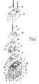
- the body 1 of the interface module shown in Figure 3 is a plastic member injected with a general parallelepiped shape having a side 2 of connection with a base of an island of solenoid valves, a facade 3, a lower face 4 for its cooperation with a support not shown and a tab 5 intended to receive means for fixing the module to this support.
- This body 1 is provided with numerous internal channels a first of which ensures the connection between an orifice of connection 6 on the front 3 and a connection orifice 7 on side 2 for the circulation of a gas under pressure.
- a second channel creates a connection inside the body between the front opening 8 and an opening 9 on the face 2 which leads to the common exhaust of the island.
- Face 2 also comprises two other orifices 10 and 11 which are the corresponding internal duct outlets respectively, in the adjacent island, to the pressure common of piloting and the common collection of exhausts piloting solenoid valves.
- the body 1 Opposite its face 4, the body 1 has a upper face 12 in which different conduits open through different orifices.
- the orifice 13 is the outlet of a conduit which is in communication with the orifice 6 and therefore the orifice 7.
- the orifices 14 and 15 are the outlet of two blind conduits.
- Port 16 is the outlet of a conduit which communicates with the orifice 10.
- the orifice 17 is the outlet of a conduit which communicates with orifice 11 and orifice 18 is the outlet of a conduit which communicates with orifice 9.
- the orifices 19 and 20 correspond respectively at the outlet of a non-functional recess and a cavity in communication with port 7.
- a seal 21 constitutes a sealing element for isolate each of the aforesaid orifices from each other.
- This selector includes connection means 23 which project from one of its faces for its connection to an external pressure pipe.
- connection means are here represented in the form a quick connector but the invention encompasses any other means of connection (threaded end, orifice threaded, as in Figures 1 and 2).
- the selector 22 has internal conduits including four 24, 25, 26, 27, are through. These internal conduits have no function with regard to the function of the selector 22. In its position shown, the conduits 24, 25, 26 and 27 are respectively in correspondence with the orifices 13, 14, 17 and 18.
- the selector 22 can be turned 180 ° to partially cover the body 1 and in this case the conduits 27 and 26 are respectively in register with the orifices 13 and 14 while the conduits 25 and 24 are actually in register with the orifices 17, 18.
- the selector 22 also includes other internal conduits, one of which connects the connection means 23 to port 16 and the other which forms a bridge between the holes 16 and 18, in the position shown in the figure. In an inverted position, the first conduit internal would connect the means 23 to the blind orifice 15, while the second would form a bridge between holes 13 and 16.
- a second selector 28 covers the selector 22 by means of a seal 29.
- This selector 28 comprises means 30 for connection to an external conduit.
- This selector 28 can like the selector 22 be placed on the latter in two positions: that represented in which the connection means 30 are turned opposite connection means 23 and that in which the connection means 30 are on the same side as those 23 of the selector 22.
- the selector 28 also includes conduits internal, one of which, not shown, forms a bridge between conduits 26, 27 or 24, 25 depending on the position of the selector 28 relative to selector 22, and of which another connects the connection means 30 either to the conduit 25 or to the conduit 26 also according to the relative position of the two selectors 28, 22.
- a screw 31 passes through all of the selectors for be screwed into a threaded hole 32 of the body 1 in order to tighten the stack thus constructed.
- a cover 33 attached to the body 1 by two screws 34, 35 reveals the face selectors which is an extension of facade 3 of body 1 of the interface module, hides the other faces selectors and constitutes a tight closing wall orifice 20.
- FIGS 4 to 7 show some of the elements already described with the same references.
- connection means 30 are connected to conduit 25, itself in register with the orifice 17 and therefore the orifice 11 where the common exhaust of the driving circuit.
- FIG 7 finally illustrates the fourth state possible interface module according to the invention.
- selectors 22 and 28 present their connection means 23 and 30 apparently, indicating that admission pressure and exhaust circuit collection piloting are independent of the pressure admission of use and collection of exhaust distributors.
- the orifice 10 communicates with the connection means 23 while the orifice 11 communicates with the means of connection 30, the internal conduits also being isolated from ports 6 and 8.
- modules simpler.
- a module according to the invention can concern only the pressure supply and contain that ports 6 and 7, that ports 10, 13 and 16, a single selector such as 22 without passages 24 to 27 and a lower cover 33.
- another module cannot concern that the exhausts with the only orifices 8, 9, 11, 17 and 18, a selector such as 28 and a cover 33 shorter.
- Such modules could frame an island of distributors on base.
Landscapes
- Engineering & Computer Science (AREA)
- Physics & Mathematics (AREA)
- Fluid Mechanics (AREA)
- Mechanical Engineering (AREA)
- General Engineering & Computer Science (AREA)
- Valve Housings (AREA)
- Magnetically Actuated Valves (AREA)
- Fluid-Pressure Circuits (AREA)
- Details Of Valves (AREA)
- Electrically Driven Valve-Operating Means (AREA)
- Multiple-Way Valves (AREA)
- Compressor (AREA)
- Fluid-Driven Valves (AREA)
Abstract
Description
- les figures 1 et 2 sont deux vues schématiques d'un module conforme à l'invention en coupe par un plan parallèle à son plan d'association avec un ílot,
- la figure 3 est une vue en perspective éclatée d'un module conforme à l'invention assurant une interface d'un ílot de distributeurs sur embase avec des conduits extérieurs tant en ce qui concerne l'alimentation en pression que l'échappement et pourvu de sélecteurs l'un affecté à la pression de pilotage et l'autre affecté à l'échappement de pilotage,
- la figure 4 est une vue extérieure en perspective du module selon la figure 3, assemblé, les sélecteurs étant dans leur position assurant une communication interne au module entre les circuits de pression d'utilisation et de pilotage et les circuits de collecte d'échappement d'utilisation et de pilotage,
- la figure 5 est une vue semblable à la figure 4 du module selon l'invention dans lequel le sélecteur isole le commun de pression du circuit de pilotage et permet l'alimentation en pression de dernier par une source extérieure,
- la figure 6 est une vue identique aux deux précédentes, dans laquelle le module selon l'invention est représenté avec une communication interne entre le commun de pression d'utilisation et l'alimentation du circuit de pilotage et une collecte de l'échappement de pilotage séparée de la collecte des échappements des distributeurs,
- la figure 7 enfin est une vue semblable à celle des trois figures précédentes, dans laquelle la position des sélecteurs est telle que l'alimentation et l'échappement du circuit de pilotage sont totalement séparés de l'alimentation et de la collecte d'échappement des actionneurs.
Claims (6)
- Module d'interface d'un ílot de distributeurs électropneumatiques sur embases, comportant un corps (1; 100) présentant au moins une face (2) de raccordement à une embase de l'ílot et, en dehors de cette face, des moyens (6, 8 ; 102) de raccordement à au moins un premier conduit extérieur, ce corps comportant au moins un canal principal interne (7, 9 ; 100), un canal secondaire (105) et un canal interne dérivé (103, 104) de liaison du canal principal au canal secondaire, lequel canal dérivé étant pourvu d'un sélecteur (22, 28 ; 106) à deux positions, assurant selon sa position, la continuité ou l'interruption de la liaison, caractérisé en ce que le sélecteur (22, 28 ; 106) comporte des moyens de connexion (23, 30 ; 110) du canal secondaire (105) à un second conduit extérieur, accessibles de l'extérieur du module lorsque le sélecteur est dans sa position d'interruption et masqués lorsque le sélecteur est dans sa position de continuité.
- Module selon la revendication 1, caractérisé en ce que le sélecteur (22, 28) surmonte le corps (1) susdit, coopère avec ce dernier par une face (12) perpendiculaire à sa face (2) de raccordement aux embases et en ce qu'il est coiffé d'un capot (33) de masquage des moyens de connexion du sélecteur audit second conduit extérieur lorsque ce sélecteur est dans sa position de continuité.
- Module selon la revendication 1 ou la revendication 2, caractérisé en ce que le canal principal est un canal de pression et en ce que le canal secondaire est un canal commun de pression de pilotage.
- Module selon la revendication 1 ou la revendication 2, caractérisé en ce que le canal principal est un canal d'échappement et en ce que le canal secondaire est un canal commun de collecte d'échappement de pilotage.
- Module selon l'une quelconque des revendications précédentes, caractérisé en ce qu'il comporte deux sélecteurs (22, 28) superposés, l'un affecté aux canaux de pression et l'autre affecté aux canaux d'échappement.
- Module selon l'une quelconque des revendications précédentes, caractérisé en ce que les moyens de connexion (23, 30) portés par le sélecteur (22, 28) sont, lorsqu'ils sont accessibles, situés sur la façade (3) du module qui porte les moyens de connexion (6, 8) au premier conduit extérieur.
Applications Claiming Priority (2)
| Application Number | Priority Date | Filing Date | Title |
|---|---|---|---|
| FR0004918 | 2000-04-17 | ||
| FR0004918A FR2807793B1 (fr) | 2000-04-17 | 2000-04-17 | Module d'interface pour ilot de distributeurs electropneumatiques |
Publications (2)
| Publication Number | Publication Date |
|---|---|
| EP1148252A1 true EP1148252A1 (fr) | 2001-10-24 |
| EP1148252B1 EP1148252B1 (fr) | 2005-07-13 |
Family
ID=8849325
Family Applications (1)
| Application Number | Title | Priority Date | Filing Date |
|---|---|---|---|
| EP01400907A Expired - Lifetime EP1148252B1 (fr) | 2000-04-17 | 2001-04-09 | Module d'interface pour ílot de distributeurs électropneumatiques |
Country Status (6)
| Country | Link |
|---|---|
| US (1) | US6408868B2 (fr) |
| EP (1) | EP1148252B1 (fr) |
| JP (1) | JP3497835B2 (fr) |
| AT (1) | ATE299559T1 (fr) |
| DE (1) | DE60111887T2 (fr) |
| FR (1) | FR2807793B1 (fr) |
Families Citing this family (10)
| Publication number | Priority date | Publication date | Assignee | Title |
|---|---|---|---|---|
| JP3825288B2 (ja) * | 2001-08-13 | 2006-09-27 | Smc株式会社 | 電磁弁用マニホールド |
| JP3985736B2 (ja) * | 2003-06-18 | 2007-10-03 | 株式会社日立製作所 | 表示装置 |
| DE102006004050B4 (de) * | 2006-01-28 | 2009-02-05 | Robert Bosch Gmbh | Druckluftverteileranordnung für eine modular aufgebaute Ventileinheit |
| FR2901851B1 (fr) * | 2006-06-02 | 2010-11-19 | Parker Hannifin France Holding | Ilot pour distibuteurs pneumatiques |
| DE102006056089A1 (de) * | 2006-11-28 | 2008-05-29 | Festo Ag & Co. | Ventileinrichtung |
| US7793678B2 (en) * | 2007-10-31 | 2010-09-14 | Lancer Partnership, Ltd | Method and apparatus for converter valve |
| WO2015118070A1 (fr) * | 2014-02-05 | 2015-08-13 | Fluid Automation Systems S.A. | Appareil et procédé de fixation de soupape |
| JP6427604B2 (ja) | 2014-06-20 | 2018-11-21 | ニューマティクス, インコーポレイテッド | 電磁弁制御システムのための区画された多岐管アセンブリ |
| DE102017108183B4 (de) * | 2017-04-18 | 2025-02-20 | Bürkert Werke GmbH & Co. KG | Elektronikmodul zum Ankoppeln an eine Modulanordnung und Modulanordnung |
| US10731677B2 (en) * | 2017-12-27 | 2020-08-04 | Mac Valves, Inc. | Pneumatic control valve manifold |
Citations (4)
| Publication number | Priority date | Publication date | Assignee | Title |
|---|---|---|---|---|
| DE1127675B (de) * | 1958-04-02 | 1962-04-12 | Concordia | Steuerschieber |
| EP0463394A1 (fr) * | 1990-06-23 | 1992-01-02 | Robert Bosch Gmbh | Distributeur à commande électromagnétique |
| EP0846872A1 (fr) * | 1996-12-05 | 1998-06-10 | Smc Corporation | Manifold pour vanne-pilote |
| EP0915259A2 (fr) * | 1997-11-10 | 1999-05-12 | Smc Corporation | Dispositif de connexion pour une soupape à voies multiples |
Family Cites Families (3)
| Publication number | Priority date | Publication date | Assignee | Title |
|---|---|---|---|---|
| US5775374A (en) * | 1994-01-06 | 1998-07-07 | Koganei Corporation | Solenoid controlled valve |
| JP3959562B2 (ja) * | 1997-10-20 | 2007-08-15 | Smc株式会社 | パイロット式切換弁 |
| JP3959563B2 (ja) * | 1997-10-20 | 2007-08-15 | Smc株式会社 | パイロット式切換弁 |
-
2000
- 2000-04-17 FR FR0004918A patent/FR2807793B1/fr not_active Expired - Lifetime
-
2001
- 2001-04-09 AT AT01400907T patent/ATE299559T1/de not_active IP Right Cessation
- 2001-04-09 EP EP01400907A patent/EP1148252B1/fr not_active Expired - Lifetime
- 2001-04-09 DE DE60111887T patent/DE60111887T2/de not_active Expired - Lifetime
- 2001-04-17 JP JP2001118292A patent/JP3497835B2/ja not_active Expired - Lifetime
- 2001-04-17 US US09/835,552 patent/US6408868B2/en not_active Expired - Lifetime
Patent Citations (4)
| Publication number | Priority date | Publication date | Assignee | Title |
|---|---|---|---|---|
| DE1127675B (de) * | 1958-04-02 | 1962-04-12 | Concordia | Steuerschieber |
| EP0463394A1 (fr) * | 1990-06-23 | 1992-01-02 | Robert Bosch Gmbh | Distributeur à commande électromagnétique |
| EP0846872A1 (fr) * | 1996-12-05 | 1998-06-10 | Smc Corporation | Manifold pour vanne-pilote |
| EP0915259A2 (fr) * | 1997-11-10 | 1999-05-12 | Smc Corporation | Dispositif de connexion pour une soupape à voies multiples |
Also Published As
| Publication number | Publication date |
|---|---|
| JP2002022044A (ja) | 2002-01-23 |
| US6408868B2 (en) | 2002-06-25 |
| FR2807793A1 (fr) | 2001-10-19 |
| DE60111887D1 (de) | 2005-08-18 |
| US20010029987A1 (en) | 2001-10-18 |
| FR2807793B1 (fr) | 2002-05-31 |
| DE60111887T2 (de) | 2006-04-20 |
| EP1148252B1 (fr) | 2005-07-13 |
| JP3497835B2 (ja) | 2004-02-16 |
| ATE299559T1 (de) | 2005-07-15 |
Similar Documents
| Publication | Publication Date | Title |
|---|---|---|
| EP1148252B1 (fr) | Module d'interface pour ílot de distributeurs électropneumatiques | |
| US5725255A (en) | Fixture for fitting pipe joint to change-over valve | |
| US6415818B2 (en) | Diaphragm-type solenoid valve | |
| EP1979625B1 (fr) | Dispositif de commande d'un circuit consommateur de gaz comprime et generateur de vide faisant application | |
| WO2001090611A3 (fr) | Soupape de commande de la pression de reservoir de carburant | |
| EP0108665B1 (fr) | Filtre à fluide | |
| GB9811398D0 (en) | Spool valve | |
| US5983921A (en) | Directional-control-valve-connected body | |
| EP1351776B1 (fr) | Module de bloc changeur de teinte pour installation de peinture | |
| WO1995028591A1 (fr) | Vanne de commutation | |
| EP0709577A1 (fr) | Valve à quatre orifices de raccordement et deux positions | |
| FR2511448A1 (fr) | Systeme modulaire de distribution d'un fluide sous pression de commande d'un dispositif moteur comprenant au moins un distributeur principal et au moins une unite auxiliaire telle qu'un demarreur progressif ou purgeur-bloqueur, montee en amont du distributeur | |
| CA1053535A (fr) | Robinet selecteur modulaire | |
| EP0466576A1 (fr) | Perfectionnements apportés aux chaudières mixtes de chauffage central | |
| EP1155271B1 (fr) | Echangeur thermique a plaques, a vanne integree | |
| FR2795494A1 (fr) | Vanne pour la distribution d'eau et eventuellement d'air, dans les installations de pulverisation d'eau sous pression, en vue de la fabrication de neige par exemple | |
| EP1298327A1 (fr) | Element intercalaire d'isolation dans un ilot de modules de distribution | |
| EP1054199B1 (fr) | Vanne motorisée pour la constitution d'un ensemble de distribution sélective d'un fluide de circulation | |
| FR2582061A1 (fr) | Dispositif d'embase pour un distributeur d'un fluide sous pression destine a commander un dispositif moteur | |
| EP2024649A1 (fr) | Ilot pour distributeurs pneumatiques | |
| CH636412A5 (fr) | Bloc de commande pneumatique pour securite bi-manuelle. | |
| EP0216675B1 (fr) | Valves cartouches à insérer multi-fonctions coaxiales et application à la commande d'un vérin à double effet | |
| FR2654350A1 (fr) | Poste a soupape d'alarme pour installations d'extinction des incendies. | |
| EP1065387B1 (fr) | Dispositif d'assemblage d'au moins deux éléments de commande par fluide sous pression | |
| EP1067069A3 (fr) | Vanne de dérivation |
Legal Events
| Date | Code | Title | Description |
|---|---|---|---|
| PUAI | Public reference made under article 153(3) epc to a published international application that has entered the european phase |
Free format text: ORIGINAL CODE: 0009012 |
|
| AK | Designated contracting states |
Kind code of ref document: A1 Designated state(s): AT BE CH CY DE DK ES FI FR GB GR IE IT LI LU MC NL PT SE TR |
|
| AX | Request for extension of the european patent |
Free format text: AL;LT;LV;MK;RO;SI |
|
| 17P | Request for examination filed |
Effective date: 20020222 |
|
| AKX | Designation fees paid |
Free format text: AT BE CH CY DE DK ES FI FR GB GR IE IT LI LU MC NL PT SE TR |
|
| 17Q | First examination report despatched |
Effective date: 20031127 |
|
| RAP1 | Party data changed (applicant data changed or rights of an application transferred) |
Owner name: PARKER HANNIFIN RAK S.A. |
|
| GRAP | Despatch of communication of intention to grant a patent |
Free format text: ORIGINAL CODE: EPIDOSNIGR1 |
|
| GRAS | Grant fee paid |
Free format text: ORIGINAL CODE: EPIDOSNIGR3 |
|
| RAP1 | Party data changed (applicant data changed or rights of an application transferred) |
Owner name: PARKER HANNIFIN FRANCE S.A.S. |
|
| GRAA | (expected) grant |
Free format text: ORIGINAL CODE: 0009210 |
|
| AK | Designated contracting states |
Kind code of ref document: B1 Designated state(s): AT BE CH CY DE DK ES FI FR GB GR IE IT LI LU MC NL PT SE TR |
|
| PG25 | Lapsed in a contracting state [announced via postgrant information from national office to epo] |
Ref country code: NL Free format text: LAPSE BECAUSE OF FAILURE TO SUBMIT A TRANSLATION OF THE DESCRIPTION OR TO PAY THE FEE WITHIN THE PRESCRIBED TIME-LIMIT Effective date: 20050713 Ref country code: TR Free format text: LAPSE BECAUSE OF FAILURE TO SUBMIT A TRANSLATION OF THE DESCRIPTION OR TO PAY THE FEE WITHIN THE PRESCRIBED TIME-LIMIT Effective date: 20050713 Ref country code: AT Free format text: LAPSE BECAUSE OF FAILURE TO SUBMIT A TRANSLATION OF THE DESCRIPTION OR TO PAY THE FEE WITHIN THE PRESCRIBED TIME-LIMIT Effective date: 20050713 Ref country code: IE Free format text: LAPSE BECAUSE OF FAILURE TO SUBMIT A TRANSLATION OF THE DESCRIPTION OR TO PAY THE FEE WITHIN THE PRESCRIBED TIME-LIMIT Effective date: 20050713 Ref country code: FI Free format text: LAPSE BECAUSE OF FAILURE TO SUBMIT A TRANSLATION OF THE DESCRIPTION OR TO PAY THE FEE WITHIN THE PRESCRIBED TIME-LIMIT Effective date: 20050713 |
|
| REG | Reference to a national code |
Ref country code: GB Ref legal event code: FG4D Free format text: NOT ENGLISH |
|
| REG | Reference to a national code |
Ref country code: CH Ref legal event code: EP |
|
| REG | Reference to a national code |
Ref country code: IE Ref legal event code: FG4D Free format text: LANGUAGE OF EP DOCUMENT: FRENCH |
|
| REF | Corresponds to: |
Ref document number: 60111887 Country of ref document: DE Date of ref document: 20050818 Kind code of ref document: P |
|
| REG | Reference to a national code |
Ref country code: CH Ref legal event code: NV Representative=s name: BOVARD AG PATENTANWAELTE |
|
| GBT | Gb: translation of ep patent filed (gb section 77(6)(a)/1977) |
Effective date: 20050912 |
|
| PG25 | Lapsed in a contracting state [announced via postgrant information from national office to epo] |
Ref country code: SE Free format text: LAPSE BECAUSE OF FAILURE TO SUBMIT A TRANSLATION OF THE DESCRIPTION OR TO PAY THE FEE WITHIN THE PRESCRIBED TIME-LIMIT Effective date: 20051013 Ref country code: DK Free format text: LAPSE BECAUSE OF FAILURE TO SUBMIT A TRANSLATION OF THE DESCRIPTION OR TO PAY THE FEE WITHIN THE PRESCRIBED TIME-LIMIT Effective date: 20051013 Ref country code: GR Free format text: LAPSE BECAUSE OF FAILURE TO SUBMIT A TRANSLATION OF THE DESCRIPTION OR TO PAY THE FEE WITHIN THE PRESCRIBED TIME-LIMIT Effective date: 20051013 |
|
| PG25 | Lapsed in a contracting state [announced via postgrant information from national office to epo] |
Ref country code: ES Free format text: LAPSE BECAUSE OF FAILURE TO SUBMIT A TRANSLATION OF THE DESCRIPTION OR TO PAY THE FEE WITHIN THE PRESCRIBED TIME-LIMIT Effective date: 20051024 |
|
| PG25 | Lapsed in a contracting state [announced via postgrant information from national office to epo] |
Ref country code: PT Free format text: LAPSE BECAUSE OF FAILURE TO SUBMIT A TRANSLATION OF THE DESCRIPTION OR TO PAY THE FEE WITHIN THE PRESCRIBED TIME-LIMIT Effective date: 20051219 |
|
| NLV1 | Nl: lapsed or annulled due to failure to fulfill the requirements of art. 29p and 29m of the patents act | ||
| REG | Reference to a national code |
Ref country code: IE Ref legal event code: FD4D |
|
| PG25 | Lapsed in a contracting state [announced via postgrant information from national office to epo] |
Ref country code: MC Free format text: LAPSE BECAUSE OF NON-PAYMENT OF DUE FEES Effective date: 20060430 Ref country code: BE Free format text: LAPSE BECAUSE OF NON-PAYMENT OF DUE FEES Effective date: 20060430 |
|
| PLBE | No opposition filed within time limit |
Free format text: ORIGINAL CODE: 0009261 |
|
| STAA | Information on the status of an ep patent application or granted ep patent |
Free format text: STATUS: NO OPPOSITION FILED WITHIN TIME LIMIT |
|
| 26N | No opposition filed |
Effective date: 20060418 |
|
| BERE | Be: lapsed |
Owner name: PARKER HANNIFIN FRANCE S.A.S. Effective date: 20060430 |
|
| PG25 | Lapsed in a contracting state [announced via postgrant information from national office to epo] |
Ref country code: LU Free format text: LAPSE BECAUSE OF NON-PAYMENT OF DUE FEES Effective date: 20060409 |
|
| PG25 | Lapsed in a contracting state [announced via postgrant information from national office to epo] |
Ref country code: CY Free format text: LAPSE BECAUSE OF FAILURE TO SUBMIT A TRANSLATION OF THE DESCRIPTION OR TO PAY THE FEE WITHIN THE PRESCRIBED TIME-LIMIT Effective date: 20050713 |
|
| REG | Reference to a national code |
Ref country code: CH Ref legal event code: PFA Owner name: PARKER HANNIFIN FRANCE S.A.S. Free format text: PARKER HANNIFIN FRANCE S.A.S.#17, RUE DES BUCHILLONS, ZI DU MONT BLANC#74100 VILLE LA GRAND (FR) -TRANSFER TO- PARKER HANNIFIN FRANCE S.A.S.#17, RUE DES BUCHILLONS, ZI DU MONT BLANC#74100 VILLE LA GRAND (FR) |
|
| REG | Reference to a national code |
Ref country code: FR Ref legal event code: PLFP Year of fee payment: 15 |
|
| REG | Reference to a national code |
Ref country code: DE Ref legal event code: R082 Ref document number: 60111887 Country of ref document: DE Representative=s name: SCHAUMBURG & PARTNER PATENTANWAELTE GBR, DE Ref country code: DE Ref legal event code: R082 Ref document number: 60111887 Country of ref document: DE Representative=s name: SCHAUMBURG & PARTNER PATENTANWAELTE MBB, DE Ref country code: DE Ref legal event code: R082 Ref document number: 60111887 Country of ref document: DE Representative=s name: SCHAUMBURG UND PARTNER PATENTANWAELTE MBB, DE |
|
| REG | Reference to a national code |
Ref country code: DE Ref legal event code: R082 Ref document number: 60111887 Country of ref document: DE Representative=s name: SCHAUMBURG & PARTNER PATENTANWAELTE MBB, DE Ref country code: DE Ref legal event code: R081 Ref document number: 60111887 Country of ref document: DE Owner name: PARKER HANNIFIN MANUFACTURING FRANCE SAS, FR Free format text: FORMER OWNER: PARKER HANNIFIN FRANCE S.A.S., VILLE LA GRAND, FR Ref country code: DE Ref legal event code: R082 Ref document number: 60111887 Country of ref document: DE Representative=s name: SCHAUMBURG UND PARTNER PATENTANWAELTE MBB, DE |
|
| REG | Reference to a national code |
Ref country code: FR Ref legal event code: TP Owner name: PARKER HANNIFIN MANUFACTURING FRANCE SAS, FR Effective date: 20151207 |
|
| REG | Reference to a national code |
Ref country code: GB Ref legal event code: 732E Free format text: REGISTERED BETWEEN 20160128 AND 20160203 |
|
| REG | Reference to a national code |
Ref country code: FR Ref legal event code: PLFP Year of fee payment: 16 |
|
| REG | Reference to a national code |
Ref country code: FR Ref legal event code: PLFP Year of fee payment: 17 |
|
| REG | Reference to a national code |
Ref country code: FR Ref legal event code: PLFP Year of fee payment: 18 |
|
| PGFP | Annual fee paid to national office [announced via postgrant information from national office to epo] |
Ref country code: FR Payment date: 20200420 Year of fee payment: 20 Ref country code: CH Payment date: 20200420 Year of fee payment: 20 Ref country code: DE Payment date: 20200420 Year of fee payment: 20 |
|
| PGFP | Annual fee paid to national office [announced via postgrant information from national office to epo] |
Ref country code: IT Payment date: 20200428 Year of fee payment: 20 Ref country code: GB Payment date: 20200427 Year of fee payment: 20 |
|
| REG | Reference to a national code |
Ref country code: DE Ref legal event code: R071 Ref document number: 60111887 Country of ref document: DE |
|
| REG | Reference to a national code |
Ref country code: CH Ref legal event code: PL |
|
| REG | Reference to a national code |
Ref country code: GB Ref legal event code: PE20 Expiry date: 20210408 |
|
| PG25 | Lapsed in a contracting state [announced via postgrant information from national office to epo] |
Ref country code: GB Free format text: LAPSE BECAUSE OF EXPIRATION OF PROTECTION Effective date: 20210408 |