EP1148235A1 - Method for manufacturing hollow piston of compressor - Google Patents
Method for manufacturing hollow piston of compressor Download PDFInfo
- Publication number
- EP1148235A1 EP1148235A1 EP00114656A EP00114656A EP1148235A1 EP 1148235 A1 EP1148235 A1 EP 1148235A1 EP 00114656 A EP00114656 A EP 00114656A EP 00114656 A EP00114656 A EP 00114656A EP 1148235 A1 EP1148235 A1 EP 1148235A1
- Authority
- EP
- European Patent Office
- Prior art keywords
- dual
- caps
- piston
- unfinished
- portions
- Prior art date
- Legal status (The legal status is an assumption and is not a legal conclusion. Google has not performed a legal analysis and makes no representation as to the accuracy of the status listed.)
- Withdrawn
Links
- 238000000034 method Methods 0.000 title claims abstract description 65
- 238000004519 manufacturing process Methods 0.000 title claims abstract description 40
- 230000009977 dual effect Effects 0.000 claims abstract description 124
- 238000003466 welding Methods 0.000 claims abstract description 92
- 238000005520 cutting process Methods 0.000 claims abstract description 38
- 238000000576 coating method Methods 0.000 claims description 13
- 239000011248 coating agent Substances 0.000 claims description 11
- 238000000227 grinding Methods 0.000 claims description 4
- 230000003746 surface roughness Effects 0.000 abstract description 3
- 239000003507 refrigerant Substances 0.000 description 12
- 238000003754 machining Methods 0.000 description 9
- 238000005242 forging Methods 0.000 description 8
- 230000006835 compression Effects 0.000 description 7
- 238000007906 compression Methods 0.000 description 7
- 238000007796 conventional method Methods 0.000 description 6
- 238000004512 die casting Methods 0.000 description 5
- 229910000838 Al alloy Inorganic materials 0.000 description 4
- 239000007787 solid Substances 0.000 description 4
- 238000005266 casting Methods 0.000 description 3
- 239000004809 Teflon Substances 0.000 description 2
- 229920006362 Teflon® Polymers 0.000 description 2
- 239000000956 alloy Substances 0.000 description 2
- 230000003247 decreasing effect Effects 0.000 description 2
- 230000000694 effects Effects 0.000 description 2
- 239000000463 material Substances 0.000 description 2
- 230000003647 oxidation Effects 0.000 description 2
- 238000007254 oxidation reaction Methods 0.000 description 2
- 238000003825 pressing Methods 0.000 description 2
- 238000007792 addition Methods 0.000 description 1
- 238000004378 air conditioning Methods 0.000 description 1
- 230000007547 defect Effects 0.000 description 1
- 238000006073 displacement reaction Methods 0.000 description 1
- 239000003562 lightweight material Substances 0.000 description 1
- 238000012986 modification Methods 0.000 description 1
- 230000004048 modification Effects 0.000 description 1
- 230000000149 penetrating effect Effects 0.000 description 1
- 230000002093 peripheral effect Effects 0.000 description 1
- 238000006467 substitution reaction Methods 0.000 description 1
Images


Classifications
-
- B—PERFORMING OPERATIONS; TRANSPORTING
- B23—MACHINE TOOLS; METAL-WORKING NOT OTHERWISE PROVIDED FOR
- B23P—METAL-WORKING NOT OTHERWISE PROVIDED FOR; COMBINED OPERATIONS; UNIVERSAL MACHINE TOOLS
- B23P15/00—Making specific metal objects by operations not covered by a single other subclass or a group in this subclass
- B23P15/10—Making specific metal objects by operations not covered by a single other subclass or a group in this subclass pistons
-
- F—MECHANICAL ENGINEERING; LIGHTING; HEATING; WEAPONS; BLASTING
- F04—POSITIVE - DISPLACEMENT MACHINES FOR LIQUIDS; PUMPS FOR LIQUIDS OR ELASTIC FLUIDS
- F04B—POSITIVE-DISPLACEMENT MACHINES FOR LIQUIDS; PUMPS
- F04B39/00—Component parts, details, or accessories, of pumps or pumping systems specially adapted for elastic fluids, not otherwise provided for in, or of interest apart from, groups F04B25/00 - F04B37/00
- F04B39/0005—Component parts, details, or accessories, of pumps or pumping systems specially adapted for elastic fluids, not otherwise provided for in, or of interest apart from, groups F04B25/00 - F04B37/00 adaptations of pistons
-
- F—MECHANICAL ENGINEERING; LIGHTING; HEATING; WEAPONS; BLASTING
- F04—POSITIVE - DISPLACEMENT MACHINES FOR LIQUIDS; PUMPS FOR LIQUIDS OR ELASTIC FLUIDS
- F04B—POSITIVE-DISPLACEMENT MACHINES FOR LIQUIDS; PUMPS
- F04B27/00—Multi-cylinder pumps specially adapted for elastic fluids and characterised by number or arrangement of cylinders
- F04B27/08—Multi-cylinder pumps specially adapted for elastic fluids and characterised by number or arrangement of cylinders having cylinders coaxial with, or parallel or inclined to, main shaft axis
- F04B27/0873—Component parts, e.g. sealings; Manufacturing or assembly thereof
- F04B27/0878—Pistons
-
- F—MECHANICAL ENGINEERING; LIGHTING; HEATING; WEAPONS; BLASTING
- F04—POSITIVE - DISPLACEMENT MACHINES FOR LIQUIDS; PUMPS FOR LIQUIDS OR ELASTIC FLUIDS
- F04B—POSITIVE-DISPLACEMENT MACHINES FOR LIQUIDS; PUMPS
- F04B39/00—Component parts, details, or accessories, of pumps or pumping systems specially adapted for elastic fluids, not otherwise provided for in, or of interest apart from, groups F04B25/00 - F04B37/00
- F04B39/14—Provisions for readily assembling or disassembling
Definitions
- the present invention relates, in general, to a method for manufacturing the piston of a variable capacity type of swash-plate compressor and, more particularly, to a method, which is capable of easily manufacturing a lightweight, hollow piston for a compressor.
- a compressor has been employed as one of the main elements of an air-conditioning apparatus for automobiles.
- the compressor is an apparatus that selectively receives power from an engine by the intermittent operation of an electromagnetic clutch, converts refrigerant gas to a condition of a high temperature and a high pressure by means of a compressing process, and discharges the refrigerant gas to the condenser.
- a swash-plate compressor is a sort of compressor.
- the swash-plate compressor is operated in such a way that a swash-plate, which is mounted to a drive shaft and is in the form of a disk, is rotated together with the drive shaft and a plurality of pistons are linearly reciprocated in the bores of a cylinder by the rotation of the swash-plate.
- refrigerant gas is sucked into the cylinder, compressed in the cylinder, and, thereafter, discharged to a condenser.
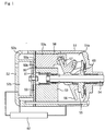
- Fig. 1 is a sectional view showing a variable capacity type of a swash-plate compressor.
- the variable capacity type of swash-plate compressor comprises front and rear housings 51 and 52 defining a crank chamber 51a, a suction chamber 52a and a discharge chamber 52b, a cylinder block 53 having a plurality of bores 53a arranged circumferentially and being positioned in the front and rear housings 51 and 52, a drive shaft 54 rotatably supported in the center portion of the cylinder block 53 while penetrating the center portion of the 'front housing 51 and being inserted into the crank chamber 51a, a lug plate 55 fixed around the drive shaft 54 so as to be rotated together with the drive shaft 54 in the crank chamber 51a, a swash-plate 56 mounted around the drive shaft 54 and hingedly connected to one side of the lug plate 55 so that its tilt angle is varied while being rotated by the rotation of the lug plate 55 and sliding on the drive shaft 54, a plurality of pistons
- variable capacity type of swash-plate compressor further comprises a pressure control valve 62 for controlling the inclination of the swash plate.
- the inclination of the swash plate changes in accordance with the difference between the pressure in the crank chamber and the pressure in the cylinder bores.
- the displacement of the compressor varies in accordance with the inclination of the swash plate.
- a process wherein refrigerant gas transferred from an evaporator is compressed and discharged to a condenser is as follows.
- the drive shaft 54 is rotated by means of the power of an engine, the lug plate 55 is rotated.
- the swash-plate 56 is rotated as the lug plate 55 is rotated, the pistons 58 are reciprocated to a distance proportional to the tilt angle of the swash-plate 56.
- the refrigerant gas is sucked from the suction chamber 52a into the bores 53a while each piston 58 is moved rearward, and the refrigerant gas compressed and discharged to the discharge chamber 52b at a high pressure, through a refrigerant gas passage while each piston 58 is moved forward.
- the weight of the piston 58 acts toward the opposite direction of the moving direction of the piston 58 and functions as an inertia force to reduce the rotating force of the drive shaft 54, the weight of the piston 58 has great influence upon the compression efficiency of the compressor.
- the piston of a compressor is generally made of lightweight material so as to improve the compression efficiency of the compressor.
- a hollow piston which is more lightweight, is developed and employed for the variable capacity type of compressor.
- the hollow piston has an inner cavity in its cylindrical head that occupies a significant portion of the piston volume.
- the hollow piston has a small inertia proportional to the weight thereof because the ratio of weight to volume is low. Therefore, the hollow piston can greatly improve the compression performance of a compressor in comparison with a solid piston that generates great inertia force during its reciprocation because the weight of the solid piston is great.
- the hollow piston is difficult in manufacture in comparison with the solid piston that may be manufactured by forming an unfinished piston by means of a forging or die casting process and, thereafter, machining the unfinished piston into a complete piston.
- the hollow piston since it is almost impossible to manufacture the hollow piston into a single body by means of a forging or die casting process, the hollow piston should be manufactured by forming a body and a cap separately and bonding the body and the cap together into a piston. Therefore, in accordance with this manufacturing method, the inferiority ratio in finished pistons and the manufacturing cost of the piston are increased.
- the hollow piston has an advantage of compression efficiency, there have been made various attempts to develop a method of easily fabricating the hollow piston.
- a body 41 and a cap 42 are separately formed, the body 41 and the cap 42 are machined and temporarily combined together, and the body 41 and the cap 42 are welded into a piston in a vacuum state by means of an electronic beam welding.
- the body 41 is formed by means of a forging or die casting process using aluminum alloy material so as to have a central bridge portion 41a, a head portion 41b formed at one end of the bridge portion 41a, and a grip protrusion 41c formed at the other end of the bridge portion 41a
- the cap 42 is formed by means of a forging or die casting process using aluminum alloy material so as to have a head portion 42b provided with an open cavity and a grip protrusion 42c formed on the closed side of the head portion 42b (a forging or die casting step).
- the head portions 41b and 42b are cut along the dotted lines in Fig. 2 to form welding surfaces 40a and 40c so that the head portion 42b of the cap 42 is fitted into the head portion 41b of the body 41 (a welding surface cutting step).
- the head portion 42b of the cap 42 is fitted into the head portion 41b of the body 41, and the welding surface 40a of the body'41 is welded to the welding surface 40c of the cap 42 into an unfinished piston by means of the electronic beam welding while the combined body 41 and cap 42 are fixedly disposed on a jig (not shown) (an electronic beam welding step).
- the circumferential surface of the unfinished piston is cut to form a head circumferential surface 4a (a cutting after welding step). Teflon is coated on the entire surface of the unfinished piston to form a wear resisting layer (a coating step).
- the head circumferential surface 4a is ground, and bottom side of the bridge portion 41a is cut away to form a swash-plate receiving cavity 4b and a shoe socket 4c (a cutting step).
- the grip protrusions 41c and 42c are cut away to form a front surface 4d and a rear surface 4e.
- the conventional piston manufacturing method is problematic in that the welding surfaces 40a and 40c must be accurately formed because the body 41 and the cap 42 are formed separately, a relatively long period of time, that is, more than 10 seconds, is required to weld the body 41 and the cap 42 at the welding surfaces 40a and 40c, and the assembly and post-assembly treatment of the body 41 and the cap 42 are relatively difficult and complicated, thereby reducing the productivity in manufacturing the pistons and increasing the inferiority ratio in finished pistons.
- the electronic welding must be performed in a vacuum state so as to prevent the body 41 and the cap 42 of an aluminum alloy from being oxidized, expensive equipment is required, thereby increasing the equipment cost.
- fine holes are generated in the piston 4 in the process of the electronic beam welding, the durability of the piston is insufficient and the piston comes short of refrigerant gas and oil due to the leakage of the refrigerant gas and the oil through the holes.
- Japanese Pat. Publication No. 9-256952 discloses a piston manufacturing method, comprising the steps of forming an unfinished dual piston having two piston portions, machining the front surface, rear and outer circumferential surfaces of the dual piston, coating the dual piston, forming swash-plate receiving cavities and shoe sockets and parting the dual piston along its central line, thereby completing two pistons.
- the conventional method in accordance with the Japanese Pat. Publication No. 9-256952 allows the productivity in manufacturing pistons to be improved.
- the method is problematic in that it cannot be applied to the manufacture of hollow pistons. That is, the method can be applied only to the manufacture of solid pistons.
- An object of the present invention is to provide a method for manufacturing a hollow piston for a compressor, which is capable of reducing the inferiority ratio in finished products and the equipment cost for manufacturing the piston, lengthening the endurance period of the hollow piston, improving the productivity of the piston, and reducing the manufacturing cost of the piston.
- the present invention provides a method for manufacturing the hollow piston of a compressor, comprising the steps of forming a dual body and two caps separately, the dual body having two body portions that are symmetrically integrated and respectively have bridge portions and head portions, the two caps respectively having head portions that respectively have open cavities and grip protrusions that are respectively formed on the closed side surfaces of the head portions, the bridge portions respectively having rough cavities; forming welding surfaces on two couples of the opposing portions of the head portions of the dual body and the caps; welding the caps to the dual body at their welding surfaces using frictional heat by relatively rotating at least one of the caps and the dual body while the welding surfaces of the dual body are in contact with the welding surfaces of the caps, thereby forming an unfinished dual hollow piston; forming the outer circumferential surface of the piston by cutting the outer circumferential surface of the unfinished dual piston; forming a wear resisting layer on the surface of the unfinished dual piston by coating the unfinished dual piston; forming head outer circumferential surfaces by grinding the outer circumferential surfaces of the head
- the present invention provides a method for manufacturing the hollow piston of a compressor, comprising the steps of forming a dual body and two caps separately, the dual body having two body portions that are symmetrically integrated and respectively have bridge portions and head portions, the two caps respectively having head portions that respectively have open cavities and grip protrusions that are respectively formed on the closed side surfaces of the head portions, the bridge portions respectively having rough cavities; forming welding surfaces on two couples of the opposing portions of the head portions of the dual body and the caps; welding the caps to the dual body at their welding surfaces using frictional heat by relatively rotating at least one of the caps and the dual body while the welding surfaces of the dual body are in contact with the welding surfaces of the caps, thereby forming an unfinished dual hollow piston; cutting both sides and the outer circumferential surface of the unfinished dual piston; forming swash-plate receiving cavities by cutting the surfaces defining the rough cavities of the bridge portions; forming a wear resisting layer on a surface of the unfinished dual piston by coating the unfinished dual piston; parting the unfinished dual piston along its
- the present invention provides a method for manufacturing the hollow piston of a compressor, comprising the steps of forming a dual body and two caps separately, the dual body having two body portions that are symmetrically integrated and respectively have bridge portions and head portions, the two caps respectively having head portions that respectively have open cavities and grip protrusions that are respectively formed on the closed side surfaces of the head portions, the bridge portions respectively having rough cavities; forming welding surfaces on two couples of the opposing portions of the head portions of the dual body and the caps; welding the caps to the dual body at their welding surfaces using frictional heat by relatively rotating at least one of the caps and the dual body while the welding surfaces of the dual body are in contact with the welding surfaces of the caps, thereby forming an unfinished dual hollow piston; cutting both sides and the outer circumferential surface of the unfinished dual piston; forming swash-plate receiving cavities by cutting surfaces defining the rough cavities of the bridge portions; forming a wear resisting layer on a surface of the unfinished dual piston by coating the unfinished dual piston; forming hemispherical shoe sockets
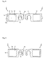
- a dual body 110 and two caps 12 are individually formed.
- the dual body 110 has two body portions 11 that are symmetrically integrated and respectively have bridge portions 11a and head portions 11b.
- the two caps 12 respectively have head portions 12b respectively having open cavities and grip protrusions 12c respectively formed on the closed side surfaces of the head portions 12b.
- the dual body 110 and the two caps 12 may be preferably formed by means of a forging or casting process.
- each body portion 11 of the dual body 110 has a bridge portion 11a having a rough cavity 11c opened to the outside and a head portion 11b integrated with the bridge portion 11a at one side of the bridge portion 11a.
- the two body portions 11 are integrated into the dual body 110 while being symmetrically arranged side by side.
- the two body portions 11 are integrated into the dual body 110 with their two bridge portions 11a being in contact with each other. Since the two bridge portions 11a are in contact with each other, two head portions 11b are situated on opposite sides.
- Each of the caps 12 has the cylindrical head portion 12b whose one side is open and the grip protrusion 12c that is formed on the closed surface of the cap 12
- the dual body 11 and the caps 12 are all made of aluminum alloy by means of a forging or casting process, and are formed to be thick so as to have a machining clearance.
- This step is performed by means of a simple planning process. Since the welding surfaces 10a and 10b are formed by means of a simple planning process only so as to provide the flatness and surface roughness suitable for a friction welding described below, the cutting process for this step is simple in comparison with the cutting process for the conventional piston. Therefore, this step allows the inferiority ratio of finished products and the manufacturing cost to be decreased effectively.
- the caps 12 are pressed and rotated while the welding surfaces 10a of the dual body 110 are in contact with the welding surfaces 10b of the caps 12 and the grip protrusions 12c of the caps 12 are supported by a jig. Frictional heat is generated on the welding surfaces 10a and 10b due to the pressing and rotation of the caps 12, and the welding surfaces 10a and 10b are welded due to the frictional heat. As a result, the caps 12 are welded to the dual body 110 at both sides of the dual body 110. That is, there is obtained an unfinished dual piston 10 in which two piston portions respectively having inner cavities are integrated into a single body.
- the step may be performed at a normal temperature in the atmosphere by means of a simple device that is capable of pressing and rotating the caps 12. Therefore, this step allows the equipment cost to be decreased. Additionally, the conventional electronic beam welding process requires about 10 seconds, while this friction welding process requires about 5 seconds. Therefore, the productivity in manufacturing pistons is increased. Furthermore, since the bonding strength between the welding surfaces 10a and 10b is great, the durability of the piston is improved.
- the following methods may be employed besides the foregoing method in which the caps 12 are pressed and rotated while the dual body 110 is fixed. Another method is to utilize relative rotation that is generated when one of the dual body 110 and the caps 12 is stopped while the dual body 110 and the caps 12 are rotated in a same direction. A further method is to rotate the dual body 110 while the caps 12 are pressed in inner directions. In these cases, effects similar to the effect of the foregoing method are obtainable.
- the circumferential surfaces of the unfinished dual piston 10 are cut while the unfinished piston 10 obtained in the friction welding step is fixed to a jig (not shown), so that a head circumferential surface 1a (illustrated by dotted lines in Fig. 6) is formed.
- the wear resisting layer consists of lubricative wear resisting material such as Teflon, and serves to reduce the speed of wear so as to lengthen the endurance period of the piston and to eliminate fine holes that may reduce the compression performance of the compressor.
- the head circumferential surface 1a of the unfinished dual piston 10 is ground to have a uniform surface roughness so as to minimize the friction between the inner surface of the cylinder bore of a compressor and the head circumferential surface 1a of the unfinished dual piston 10 while the piston is reciprocated within the cylinder bore.
- the surfaces defining the rough cavities 11c of the bridge portions 11a are cut to form swash-plate receiving cavities 1b into which swash-plates 1b are respectively inserted, and the surfaces defining the swash-plate receiving cavities 1b are cut to form shoe sockets 1c on which hemispheric shoes are seated.
- the unfinished dual piston 10 is parted into two unfinished pistons along its vertical central line, the two grip protrusions 12c are cut away, and both side surfaces 1d and 1e of each of two unfinished pistons are cut. As a result, there are completed two pistons that can be reciprocated smoothly within the cylinder bores.
- the inferiority ratio in finished products can be reduced and the productivity of the piston can be improved.
- the advantages of the method of the present invention are obvious in comparison with the defects of the conventional method wherein the material must be cut accurately so as to temporarily combine the body and the cap before welding and the body must be welded to the cap in a vacuum state so as to prevent the two parts from being oxidized.
- oxidation does not occur in the process of performing the method of the present invention, fine holes are not generated in the piston. Therefore, in the hollow piston manufactured in accordance with the present invention, the endurance period of the piston is lengthened and the compression performance of the compressor is not reduced in comparison with the conventional hollow piston.
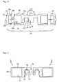
- the method of the present embodiment is similar to the method of the first embodiment except for the difference between the inner cavity 1f of the method of the first embodiment and the inner cavity 2f of the method of the second embodiment.
- each of head portions 21b respectively integrated with bridge portions 21a is long in comparison with each of the head portions 11b of the first embodiment and is in the form of a cylinder open at its outer side, and each of the head portions 22b of caps 22 is short in comparison with each of the head portions 12b of the caps 12.
- a friction welding step, a cutting after welding step, a coating step, a grinding step, a cavity forming step and a cutting step are the same as those of the first embodiment except that a jig employed in the second embodiment is different from the jig employed in the first embodiment in size.
- welding surfaces 20a and 20b are formed on the opposing portions of the head portions 21b and 22b of a dual body 210 and two caps 22 by means of a cutting process, the dual body 210 and the caps 22 are welded together at a normal temperature in the atmosphere by means of a friction welding process to form an unfinished dual piston 20, the circumferential surface of the unfinished dual piston 20 is cut to form a head circumferential surface 2a, the entire surface of the unfinished dual piston 20 is coated to form a wear resisting layer, the head circumferential surface 2a is ground, the surfaces defining the rough cavities 21c of bridge portions 21a are cut to form a swash-plate receiving cavity 2b and a shoe socket 2c, and, finally, the unfinished dual piston 20 is parted into two pistons and grip protrusions 22c are cut away.
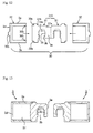
- an unfinished, solid-cylindrical dual body 31a having two bridge portions 31a and two head portions 31b and two caps 32 having open cavities are separately formed by means of a forging or casting process, which is the same as that of the first embodiment.
- stepped welding surfaces 30a and 30b are formed on the opposing portions of the head portions 31b and 32b of a dual body 310 and two caps 32 by means of a cutting process.
- the outer circumferential surfaces of the head portions 31b are cut to form stepped welding surfaces 30a, while the inner circumferential surfaces of the head portions of the caps 32 are cut to form stepped welding surfaces 30b.
- the dual body 310 and the caps 32 are relatively rotated while the stepped welding surfaces 30a are in contact with the stepped welding surfaces 30b, so that the stepped welding surfaces 30a are frictionally welded to the stepped welding surfaces 30b, thereby forming the unfinished dual piston 30.
- This embodiment is different from the previous embodiments in that the caps 32 are easily combined with the dual body 310 temporarily because the stepped welding surfaces 30a are respectively engaged with the stepped welding surfaces 30b.
- the non-described reference numerals 3a,3b,3c,3d,3e and 31c respectively designate a head outer circumferential surface, a swash-plate receiving cavity, a shoe socket, the front surface of the piston, the rear surface of the piston and the rough cavity of the bridge portion 31a.
- This embodiment is similar to the previous embodiments except for the steps of forming the outer circumferential surface of a piston by cutting the outer circumferential surface of an unfinished dual piston 10, 20 and 30 after cutting away grip portions 12c, 22c and 32c, forming swash-plate receiving cavities 1a, 2b and 3b by cutting the surfaces defining rough cavities 11c, 21c and 31c of bridge portions 11a, 21a and 31a, forming a wear resisting layer on the surface of the unfinished dual piston 10, 20 and 30 by coating the unfinished dual piston 10, 20 and 20, parting the unfinished dual piston 10, 20 and 30 into two unfinished pistons, and forming shoe sockets 1c, 2c and 3c by cutting the surfaces defining the swash-plate receiving cavities 1a, 2b and 3b.
- This embodiment is similar to the fourth embodiment except that an unfinished dual piston 10, 20 and 30 are parted into two hollow pistons 1, 2 and 3 after forming shoe sockets 1c, 2c and 3c by cutting the surfaces defining the swash-plate receiving cavities 1a, 2b and 3b.
- the present invention provides a method for manufacturing a hollow piston for a compressor, which can simplify a machining process before a welding process because a minimal machining is performed only to prepare the welding surfaces for friction welding.
- the present invention provides a method for manufacturing a hollow piston for a compressor, which can reduce the equipment cost for manufacturing the piston because two caps can be easily welded to an unfinished dual body by means of simple relative rotation and, consequently, expensive equipment is not needed for embodying the method.
- the present invention provides a method for manufacturing a hollow piston for a compressor, which can lengthen the endurance period of the hollow piston because oxidation does not occur and, therefore, fine holes are not generated in the piston, and can prevent the compression performance of the compressor from being reduced because refrigerant gas is not discharged into the hollow piston through the fine holes.
- the present invention provides a method for manufacturing a hollow piston for a compressor, which can improve the productivity in manufacturing pistons and reduce the manufacturing cost of the piston because each process can be applied to two pistons at the same time and a welding process is easy and can be performed in a short period of time.
Landscapes
- Engineering & Computer Science (AREA)
- Mechanical Engineering (AREA)
- General Engineering & Computer Science (AREA)
- Manufacturing & Machinery (AREA)
- Compressors, Vaccum Pumps And Other Relevant Systems (AREA)
- Compressor (AREA)
- Standing Axle, Rod, Or Tube Structures Coupled By Welding, Adhesion, Or Deposition (AREA)
- Pistons, Piston Rings, And Cylinders (AREA)
- Pressure Welding/Diffusion-Bonding (AREA)
Applications Claiming Priority (2)
| Application Number | Priority Date | Filing Date | Title |
|---|---|---|---|
| KR1020000020267A KR100332538B1 (ko) | 2000-04-18 | 2000-04-18 | 압축기용 중공피스톤 제조방법 |
| KR2026700 | 2000-04-18 |
Publications (1)
| Publication Number | Publication Date |
|---|---|
| EP1148235A1 true EP1148235A1 (en) | 2001-10-24 |
Family
ID=19665068
Family Applications (1)
| Application Number | Title | Priority Date | Filing Date |
|---|---|---|---|
| EP00114656A Withdrawn EP1148235A1 (en) | 2000-04-18 | 2000-07-07 | Method for manufacturing hollow piston of compressor |
Country Status (3)
| Country | Link |
|---|---|
| EP (1) | EP1148235A1 (fi) |
| JP (1) | JP2001304126A (fi) |
| KR (1) | KR100332538B1 (fi) |
Cited By (4)
| Publication number | Priority date | Publication date | Assignee | Title |
|---|---|---|---|---|
| EP1234979A3 (en) * | 2001-02-23 | 2004-06-23 | Kabushiki Kaisha Toyota Jidoshokki | Manufacturing method for a compressor piston |
| DE10306792A1 (de) * | 2003-01-23 | 2004-08-19 | Zexel Valeo Compressor Europe Gmbh | Kolben, insbesondere für einen Axialkolben-Verdichter, und Verfahren zur Herstellung desselben |
| WO2010020240A3 (de) * | 2008-08-22 | 2010-04-15 | Neumayer Tekfor Holding Gmbh | Axialkolbenmaschine |
| WO2018104763A1 (en) * | 2016-12-06 | 2018-06-14 | Mahle International Gmbh | Method of manufacturing variable-displacement pistons |
Families Citing this family (3)
| Publication number | Priority date | Publication date | Assignee | Title |
|---|---|---|---|---|
| KR100752128B1 (ko) * | 2006-06-30 | 2007-08-24 | 재단법인 포항산업과학연구원 | 중공 피스톤 제조 장치 및 방법 |
| KR100730909B1 (ko) * | 2007-03-28 | 2007-06-21 | (주)두선 | 사판식 압축기용 피스톤 헤드 절단장치 |
| CN112324743B (zh) * | 2020-11-19 | 2022-02-22 | 北京航空航天大学 | 一种轻量化活塞 |
Citations (5)
| Publication number | Priority date | Publication date | Assignee | Title |
|---|---|---|---|---|
| DE974022C (de) * | 1955-06-19 | 1960-08-18 | Mahle Kg | Verfahren zum gleichzeitigen Herstellen von zwei Topfkolben |
| JPH09256952A (ja) | 1996-03-19 | 1997-09-30 | Calsonic Corp | 斜板式コンプレッサの片頭式ピストンの製造方法 |
| EP0959227A2 (en) * | 1998-05-20 | 1999-11-24 | Kabushiki Kaisha Toyoda Jidoshokki Seisakusho | Piston and method of manufacture |
| EP1087135A2 (en) * | 1999-09-21 | 2001-03-28 | Kabushiki Kaisha Toyoda Jidoshokki Seisakusho | Non-axisymmetric hollow swash plate compressor piston |
| EP1134412A2 (en) * | 2000-03-15 | 2001-09-19 | Kabushiki Kaisha Toyoda Jidoshokki Seisakusho | Method and apparatus for producing hollow piston for compressor by forging |
Family Cites Families (2)
| Publication number | Priority date | Publication date | Assignee | Title |
|---|---|---|---|---|
| JP2000154776A (ja) * | 1998-11-19 | 2000-06-06 | Showa Denko Kk | 斜板式コンプレッサー用片頭式ピストンの製造方法 |
| JP2000345963A (ja) * | 1999-05-31 | 2000-12-12 | Toyota Autom Loom Works Ltd | 片頭式ピストン製造用素材の製造方法 |
-
2000
- 2000-04-18 KR KR1020000020267A patent/KR100332538B1/ko not_active Expired - Lifetime
- 2000-06-13 JP JP2000177188A patent/JP2001304126A/ja active Pending
- 2000-07-07 EP EP00114656A patent/EP1148235A1/en not_active Withdrawn
Patent Citations (6)
| Publication number | Priority date | Publication date | Assignee | Title |
|---|---|---|---|---|
| DE974022C (de) * | 1955-06-19 | 1960-08-18 | Mahle Kg | Verfahren zum gleichzeitigen Herstellen von zwei Topfkolben |
| JPH09256952A (ja) | 1996-03-19 | 1997-09-30 | Calsonic Corp | 斜板式コンプレッサの片頭式ピストンの製造方法 |
| EP0896854A1 (en) * | 1996-03-19 | 1999-02-17 | Calsonic Corporation | Method of producing piston for swash plate compressor |
| EP0959227A2 (en) * | 1998-05-20 | 1999-11-24 | Kabushiki Kaisha Toyoda Jidoshokki Seisakusho | Piston and method of manufacture |
| EP1087135A2 (en) * | 1999-09-21 | 2001-03-28 | Kabushiki Kaisha Toyoda Jidoshokki Seisakusho | Non-axisymmetric hollow swash plate compressor piston |
| EP1134412A2 (en) * | 2000-03-15 | 2001-09-19 | Kabushiki Kaisha Toyoda Jidoshokki Seisakusho | Method and apparatus for producing hollow piston for compressor by forging |
Cited By (5)
| Publication number | Priority date | Publication date | Assignee | Title |
|---|---|---|---|---|
| EP1234979A3 (en) * | 2001-02-23 | 2004-06-23 | Kabushiki Kaisha Toyota Jidoshokki | Manufacturing method for a compressor piston |
| DE10306792A1 (de) * | 2003-01-23 | 2004-08-19 | Zexel Valeo Compressor Europe Gmbh | Kolben, insbesondere für einen Axialkolben-Verdichter, und Verfahren zur Herstellung desselben |
| DE10306792B4 (de) * | 2003-01-23 | 2007-03-22 | Valeo Compressor Europe Gmbh | Kolben, insbesondere für einen Axialkolben-Verdichter, und Verfahren zur Herstellung desselben |
| WO2010020240A3 (de) * | 2008-08-22 | 2010-04-15 | Neumayer Tekfor Holding Gmbh | Axialkolbenmaschine |
| WO2018104763A1 (en) * | 2016-12-06 | 2018-06-14 | Mahle International Gmbh | Method of manufacturing variable-displacement pistons |
Also Published As
| Publication number | Publication date |
|---|---|
| KR100332538B1 (ko) | 2002-04-13 |
| KR20010096245A (ko) | 2001-11-07 |
| JP2001304126A (ja) | 2001-10-31 |
Similar Documents
| Publication | Publication Date | Title |
|---|---|---|
| US6381842B2 (en) | Method of producing swash plate type compressor piston | |
| JP3234913B2 (ja) | 圧縮機用中空ピストンの製造方法 | |
| EP0959227A2 (en) | Piston and method of manufacture | |
| EP1148235A1 (en) | Method for manufacturing hollow piston of compressor | |
| EP1253318B1 (en) | Swash plate type compressor and shoe for the same | |
| US6488454B1 (en) | Method for machining shoe pocket for piston in variable displacement swash plate type compressor | |
| KR100388826B1 (ko) | 압축기용 중공 피스톤 및 그 제조방법 | |
| JP2002227763A (ja) | 圧縮機用ピストン及びこれを用いた圧縮機 | |
| KR101281385B1 (ko) | 사판식 압축기의 피스톤 제조방법 | |
| US20020018725A1 (en) | Hollow head piston and compressor having the same | |
| EP1126166A2 (en) | Hollow piston for a compressor | |
| EP1126167A2 (en) | Method of producing swash plate type compressor piston | |
| US20020031433A1 (en) | Variable displacement compressors | |
| JPH06336977A (ja) | 揺動斜板式圧縮機におけるピストン | |
| KR20030046352A (ko) | 압축기용 중공 피스톤 및 그 제조방법 | |
| EP1079108A2 (en) | Method of forming hollow head portion of piston for swash plate type compressor | |
| JP4314405B2 (ja) | 可変容量型斜板式圧縮機 | |
| US20090151552A1 (en) | Shoe for compressors | |
| JP3018746B2 (ja) | 容量可変型斜板式圧縮機 | |
| WO2007142198A1 (ja) | 流体機械 | |
| KR20050023837A (ko) | 압축기용 중공 피스톤 및 이의 제조방법 | |
| JP2002004063A (ja) | 金属皮膜形成方法 | |
| KR20040064797A (ko) | 자동차 공조장치용 사판식 압축기의 피스톤 구조 및 그제조 방법 | |
| JP2002202052A (ja) | 可変容量型圧縮機 | |
| JP2001073937A (ja) | 斜板式圧縮機用ピストン |
Legal Events
| Date | Code | Title | Description |
|---|---|---|---|
| PUAI | Public reference made under article 153(3) epc to a published international application that has entered the european phase |
Free format text: ORIGINAL CODE: 0009012 |
|
| AK | Designated contracting states |
Kind code of ref document: A1 Designated state(s): DE FR GB IT PT SE Kind code of ref document: A1 Designated state(s): AT BE CH CY DE DK ES FI FR GB GR IE IT LI LU MC NL PT SE |
|
| AX | Request for extension of the european patent |
Free format text: AL;LT;LV;MK;RO;SI |
|
| 17P | Request for examination filed |
Effective date: 20011123 |
|
| AKX | Designation fees paid |
Free format text: DE FR GB IT PT SE |
|
| STAA | Information on the status of an ep patent application or granted ep patent |
Free format text: STATUS: THE APPLICATION HAS BEEN WITHDRAWN |
|
| 18W | Application withdrawn |
Effective date: 20060612 |