EP1147820A2 - Rücksaugventil für Heissschmelzklebstoff - Google Patents
Rücksaugventil für Heissschmelzklebstoff Download PDFInfo
- Publication number
- EP1147820A2 EP1147820A2 EP01108283A EP01108283A EP1147820A2 EP 1147820 A2 EP1147820 A2 EP 1147820A2 EP 01108283 A EP01108283 A EP 01108283A EP 01108283 A EP01108283 A EP 01108283A EP 1147820 A2 EP1147820 A2 EP 1147820A2
- Authority
- EP
- European Patent Office
- Prior art keywords
- valve
- snuffback
- highly viscous
- seat member
- viscous materials
- Prior art date
- Legal status (The legal status is an assumption and is not a legal conclusion. Google has not performed a legal analysis and makes no representation as to the accuracy of the status listed.)
- Granted
Links
Images


Classifications
-
- F—MECHANICAL ENGINEERING; LIGHTING; HEATING; WEAPONS; BLASTING
- F16—ENGINEERING ELEMENTS AND UNITS; GENERAL MEASURES FOR PRODUCING AND MAINTAINING EFFECTIVE FUNCTIONING OF MACHINES OR INSTALLATIONS; THERMAL INSULATION IN GENERAL
- F16K—VALVES; TAPS; COCKS; ACTUATING-FLOATS; DEVICES FOR VENTING OR AERATING
- F16K23/00—Valves for preventing drip from nozzles
-
- B—PERFORMING OPERATIONS; TRANSPORTING
- B05—SPRAYING OR ATOMISING IN GENERAL; APPLYING FLUENT MATERIALS TO SURFACES, IN GENERAL
- B05C—APPARATUS FOR APPLYING FLUENT MATERIALS TO SURFACES, IN GENERAL
- B05C5/00—Apparatus in which liquid or other fluent material is projected, poured or allowed to flow on to the surface of the work
- B05C5/02—Apparatus in which liquid or other fluent material is projected, poured or allowed to flow on to the surface of the work the liquid or other fluent material being discharged through an outlet orifice by pressure, e.g. from an outlet device in contact or almost in contact, with the work
- B05C5/0225—Apparatus in which liquid or other fluent material is projected, poured or allowed to flow on to the surface of the work the liquid or other fluent material being discharged through an outlet orifice by pressure, e.g. from an outlet device in contact or almost in contact, with the work characterised by flow controlling means, e.g. valves, located proximate the outlet
Definitions
- the present invention relates generally to hot melt adhesive dispensing systems, and more particularly to a new and improved snuffback valve for dispensing hot melt adhesive whereby quick shutoff of the adhesive supply is able to be achieved at the end of a dispensing operation and during closure of the valve such that undesirable stringing of the adhesive does not occur.
- the dispensing system comprise what is known in the art as a snuffback valve by means of which shut off of the dispensed adhesive is readily achieved upon closure of the valve whereby stringing of the adhesive does not occur.
- a snuffback valve By means of which shut off of the dispensed adhesive is readily achieved upon closure of the valve whereby stringing of the adhesive does not occur.
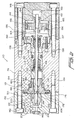
- FIGURE 1 One type of known PRIOR ART snuffback valve is disclosed in FIGURE 1 wherein the snuffback valve is generally indicated by the reference character 10.
- the snuffback valve 10 is adapted to be fixedly mounted upon a valve stem, not shown, which, in turn, is adapted to be fixedly connected, for example, to a piston drive, also not shown, by means of which the snuffback valve is moved linearly with respect to its valve seat member, not shown, so as to attain its relative opened and closed positions with respect to the valve seat.
- the PRIOR ART snuffback valve 10 comprises a substantially cylindrical structure having an axis 11, and is seen to comprise a first bore 12 and a second counterbored portion 13 with a shoulder 14 defined therebetween.
- the valve stem not shown, extends through the counterbored portion 13 and the valve end of the stem is seated upon the shoulder portion 14.
- a bolt type fastener not shown, extends through bore 12 and threadedly engages the valve end of the valve stem, not shown, so as to fixedly mount the valve stem within the valve 10.
- the valve 10 further comprises a cylindrical throat portion 15 which has an external peripheral cylindrical surface portion 16 wherein the external surface portion 16 is adapted to be disposed internally within the valve seat member, not shown, when the snuffback valve 10 is moved to its closed position so as to cooperate with the valve seat member in terminating flow of the adhesive.
- An annular tolerance, gap, or space is defined between the external cylindrical surface portion 16 of the snuffback valve 10 and the internal peripheral cylindrical surface portion of the valve seat member, not shown, so as to readily permit linear movement of the snuffback valve 10 with respect to its valve seat member, not shown, during opening and closing cycles of the valve, as well as to define or determine the snuffback action of the valve 10.
- the snuffback valve 10 Downstream of the throat portion 15, the snuffback valve 10 comprises an external frusto-conical surface portion 18 which is adapted to be mated with a complementarily shaped frusto-conical surface portion of the valve seat member, not shown, when the snuffback valve 10 is disposed at its closed position and is therefore seated upon the valve seat member.
- the snuffback valve 10 comprises a second cylindrical portion 20 having an external peripheral cylindrical surface portion 22 which is disposed downstream of the frusto-conical portion 18 as considered in the dispensing direction of the hot melt adhesive.
- the external diametrical extent of the second peripheral cylindrical surface portion 20 is substantially greater than that of the throat portion 15 such that the external peripheral cylindrical surface portion 22 of the second cylindrical portion 20 cooperates with an internal peripheral cylindrical surface portion of a valve seat adapter or dispensing block, not shown, so as to define a discharge path for the adhesive to be dispensed.
- the front or downstream face 24 of the snuffback valve 10 is disposed perpendicular to the axis 11 of the snuffback valve 10, and that the diametrical extent of the front or downstream face 24 of the snuffback valve 10 is such as to extend radially outwardly with respect to the axis 11 and has an external diametrical extent which is substantially equivalent to that of the second cylindrical portion 20.
- the throat portion 15 of the PRIOR ART snuffback valve 10 has a substantially elongated axial length dimension.
- the external diametrical extent of the throat portion 15 is such that, as has been noted hereinbefore, a relatively large clearance of, for example, 0.010 inches, is defined between the external peripheral cylindrical surface portion 16 of the snuffback valve 10 and the internal peripheral cylindrical surface portion of the valve seat member, not shown.
- the snuffback valve 10 causes a phenomenon, known as bursting, to occur when a new adhesive dispensing cycle is commenced.
- Bursting is the sudden expulsion, discharge, or dispensing, upon the commencement of a new adhesive dispensing operation or cycle, of a predetermined amount or glob of adhesive which residually remains disposed between the downstream end or front face of the snuffback valve and the exit orifice, not shown, of the adhesive dispensing mechanism when a previous dispensing operation or cycle is terminated.
- the front face or surface 24 of the snuffback valve 10 therefore acts, in effect, as a type of plow forcing the glob or residual adhesive to be suddenly dispensed as a result of the linear movement of the valve 10 attendant the opening of the valve 10 and the unseating of the throat portion 15 of the valve 10 with respect to the valve seat member upon commencement of a subsequent dispensing cycle or operation.
- valve wherein the structure of the valve is such that when dispensing of, for example, highly viscous materials, such as, for example, hot-melt adhesives, is to be achieved, the various operational drawbacks and disadvantages characteristic of such dispensing systems, such as, for example, stringing and bursting, do not occur, and in addition, the valve is characterized by means of a relatively short movement stroke with a relatively quick operational response time.
- highly viscous materials such as, for example, hot-melt adhesives
- Another object of the present invention is to provide a new and improved snuffback valve for use in connection with the dispensing of highly viscous materials, such as, for example, hot melt adhesives, which can effectively overcome the various operational drawbacks of conventional snuffback valves.
- An additional object of the present invention is to provide a new and improved and improved snuffback valve for use in connection with the dispensing of highly viscous materials, such as, for example, hot melt adhesives, which can effectively prevent the occurrence of bursting and stringing upon the commencement and termination of dispensing operations.
- a further object of the present invention is to provide a new and improved snuffback valve for use in connection with the dispensing of highly viscous materials, such as, for example, hot melt adhesives, which also exhibits a relatively short operational stroke and attendant response time during both the opening and closure movements of the valve member with respect'to its valve seat, and in. addition, increased service life of the seal members.
- highly viscous materials such as, for example, hot melt adhesives
- a new and improved snuffback valve which comprises a poppet type valve which has a leading or downstream end portion having a substantially frusto-conical configuration whereby such leading or downstream end portion is effectively aerodynamic with respect to the highly viscous material such that the occurrence of bursting, as characteristic of PRIOR ART snuffback valves, is effectively eliminated.
- the snuffback valve of the present invention comprises a trailing or upstream end portion which also has a substantially frusto-conical configuration, and the trailing or upstream frusto-conically configured end portion also has associated therewith an annular shoulder portion disposed substantially perpendicular to the longitudinal axis of the poppet valve.
- the shoulder portion thus forms a sharp, right-angled edge region with respect to the large-diameter main cylindrical portion of the poppet valve, and in addition, the shoulder portion also forms in effect a rearwardly facing plow portion.
- shoulder portion serve to disturb the flow parameters or characteristics of the viscous material, and in addition, serve to establish and maintain partial vacuum conditions within the poppet valve chamber during the valve closing cycle in such a manner that, together with the fact that a substantially small tolerance or gap is defined between the throat portion of the poppet valve and the valve seat member, the phenomenon of stringing is likewise effectively eliminated.
- FIGURE 2 a first embodiment of the new and improved snuffback valve assembly, constructed in accordance with the teachings and principles of the present invention, is illustrated and is generally indicated by the reference character 110.
- the reference character 110 in connection with the detailed description of the snuffback valves of the present invention, parts corresponding to those of the PRIOR ART snuffback valve will be denoted by similar reference characters, where possible, such that comparisons between the valves of the present invention and that of the PRIOR ART can be readily made, however, the reference characters denoting the components parts of the valves of the present invention will be within the hundred series.
- the snuffback valve assembly 110 is accordingly seen to comprise a main body member 126 wherein a seal cartridge assembly 128 is disposed within a first end of the main body member 126, while a valve seat member 130 is disposed within a second opposite end of the main body member 126.
- a valve seat adapter 132 is fixedly attached to the second end of the main body member 126 by means of a plurality of bolt fasteners 134 whereby the valve seat member 130 is secured within the valve assembly 110 as a result of being trapped between counterbored shoulder portions 131 and 133, respectively, of the main body member 126 and the valve seat adapter 132.
- an air cylinder 136 is fixedly attached to the first end of the main body member 126 by means of a plurality of bolt fasteners 138 whereby the seal cartridge assembly 128 is secured within the valve assembly 110 as a result of being trapped between counterbored shoulder portions 135 and 137, respectively, of the main body member 126 and the air cylinder 136.
- the valve seat adapter 132 is provided with an exit orifice 140 through which a highly viscous material, such as, for example, a hot melt adhesive, is able to be discharged, dispensed, or deposited onto, for example, a substrate, not shown.
- a poppet valve member 142 is provided for cooperation with the valve seat member 130 for controlling the flow of the highly viscous material, such as, for example, a hot melt adhesive, from the interior of the main body member 126 toward the exit orifice 140 depending upon the disposition of the poppet valve member 142 with respect to the valve seat member 130.
- the poppet valve member 142 is fixedly mounted upon a forward end of a valve stem 144 by means of, for example, a suitable brazing operation.
- the rear end portion of the valve stem 144 is threaded as at 146, and a piston 148 is threadedly engaged upon the threaded portion 146 of the valve stem 144.
- the threaded disposition of the piston 148 upon the threaded portion 146 of the valve stem 144 renders the same adjustable so as to predetermine the stroke of the valve member 142.
- the piston 148 has a forwardly projecting boss portion 150 which is adapted to engage the rear end of the seal cartridge assembly 128 when the piston 148 is moved forwardly so as to cause unseating of the poppet valve member 142 with respect to the valve seat member 130 and the opening of the valve assembly 110 whereby the hot melt adhesive material can be dispensed or discharged through the exit orifice 140 as will be more fully discussed hereinafter.
- the piston 148 has a rearwardly projecting boss portion 152 which is adapted to be engaged by means of a locknut 154 which is also threadedly secured upon the threaded portion 146 of the valve stem 144 so as to maintain the aforenoted predetermined disposition of the piston 148 upon the valve stem 144 and thereby adjustably fix the stroke of the valve member 142.
- the piston 148 is further provided with a peripheral recess 156 within which an O-ring seal member 158 is disposed so as to provide sealing between the periphery of the piston 148 and the interior peripheral wall surface 160 of the air cylinder 136.
- the piston 148 is adapted to be moved in a reciprocal manner, so as to in turn move the valve member 142 between its opened and closed positions with respect to the valve seat member 130, by means of pressurized air respectively and selectively supplied, from a suitable source, not shown, to an upstream air chamber 162 and a downstream air chamber 164 defined within the air cylinder 136.
- the pressurized air admitted to upstream chamber 162, and used for moving the piston 148 in the forward direction so as to achieve rapid opening of the valve member 142 with respect to the valve seat member 130 depending upon the particular application requirements be at a pressure level of, for example, 30 psi, although the pressure level can be within the range of 20-90 psi, which also partially contributes to the elimination of the bursting phenomenon characteristic of the PRIOR ART snuffback valves as will be further discussed hereinafter.
- the pressurized air admitted to downstream chamber 164, and used for moving the piston 148 in the rearward direction so as to achieve closure of the valve member 142 with respect to the valve seat member 130, is preferably at a pressure level of, for example, 80 psi, although the pressure level can be within the range of 50-90 psi, whereby rapid closure of the valve member 142 is ensured so as to enhance or facilitate the snuffback operation of the valve member 142.
- valve assembly 110 may experience a failure in the supply of pressurized air into the downstream chamber 164
- springs may be disposed within the downstream chamber 164 and interposed between the rear end of the seal cartridge assembly 128 and the piston 148 so as to bias the piston 148 in the direction whereby valve member 142 is assuredly seated upon valve seat member 130.
- a space 166, defined between the rear end portion of the valve seat member 130 and the forward end portion of the seal cartridge assembly 128, is adapted to receive the input flow of the hot melt adhesive, from a suitable source, not shown, such that the hot melt adhesive can then flow through the valve seat member 130, past the poppet valve member 142, and out the exit orifice 140 when the valve member 142 has been moved so as to be unseated from the valve seat member 130.
- the valve seat member 130 is provided with a first O-ring member 168 disposed within a circumferential recess 170 defined within an external peripheral surface portion of its axially extending body portion 172 such that the O-ring member 168 sealingly engages a counterbored shoulder portion 174 of the main body member 126.
- a second O-ring member 176 is similarly disposed within an annular recess 178 defined within the front face 180 of the valve seat member 130 so as to sealingly engage the shoulder portion 133 of the valve seat adapter 132.
- the seal cartridge assembly 128 comprises a first axially forward seal assembly 182 sealingly disposed around valve stem 144 so as to effectively prevent the transmission or migration of any adhesive from space 166 rearwardly along valve stem 144, and a second axially rearward seal assembly 184 sealingly disposed around valve stem 144 so as to effectively prevent the transmission or migration of any pressurized air from downstream chamber 164 forwardly along valve stem 144.
- An annular gasket 186 is also interposed between a shoulder portion 188 of the seal cartridge assembly 128 and the shoulder portion 135 of the main body member 126.
- the interior bore region of the valve seat member 130 is seen to comprise three, radially inwardly projecting bearing members 190 equiangularly spaced with respect to each other at 120° intervals.
- the bearing members 190 serve to radially support the valve stem 144 during its reciprocal movements attendant the opening and closing of the poppet valve member 142, and the bearing members 190 also serve to separate an upstream adhesive supply chamber 192 of the valve seat member 130 from a downstream valve throat chamber 194.
- spaces 196 are defined between respective pairs of the bearing members 190.
- the entranceway into the downstream valve throat chamber 194 is chamfered as at 198, and the chamfer angle A is noted as being 59°.
- the poppet valve member 142 has an upstream throat portion 115 for disposition within the downstream valve throat chamber 194 of the valve seat member 130, however, unlike the valve member 10 of the PRIOR ART as shown in FIGURE 1, the clearance or tolerance gap defined between the external peripheral surface of the throat portion 115 of the valve member 142 and the internal peripheral surface 200 of the valve throat chamber 194 can be in the range of 0.001-0.030 inches depending upon various conditions, for example, the particular adhesive, the glue application, and the like.
- this clearance or tolerance gap comprises a tolerance or clearance gap that can be smaller than the tolerance or clearance gap defined between the external peripheral surface 16 of the valve member 10 and its valve seat member, not shown, by means of a factor of ten.
- This significant decrease in the clearance or tolerance space or gap comprises one factor which leads to a substantial improvement of the snuffback characteristics of the valve assembly 110 of the present invention.
- the poppet valve member 142 has an external frusto-conical surface portion 118 and a cylindrical portion 120, the external peripheral cylindrical surface 122 of which cooperates with an internal peripheral cylindrical surface portion 202 of a poppet valve chamber 204 so as to define a predetermined annular flow passage therebetween through which the hot melt adhesive will flow so as to be dispensed through the poppet valve chamber 204 and the exit orifice 140.
- the tolerance or clearance gap defined between the external peripheral cylindrical surface 122 of the cylindrical portion 120 of the poppet valve member 142 and the internal peripheral cylindrical surface portion 202 of the poppet valve chamber 204 is 0.010 inches.
- the angle of frusto-conical surface 118 is indicated as angle B in FIGURE 5 and is 58°, it being noted that the angle B of the frusto-conical surface 118 is just slightly different from the angle A of the chamfered surface of the valve seat member 130 such that precise surface-to-surface contact between the frusto-conical surface 118 of the valve member 142 and the chamfered surface 198 of the valve seat member 130 is desirably avoided so as to prevent the creation of any valve-sticking problems.
- valve member 10 of the PRIOR ART as disclosed in FIGURE 1 , it is noted further that the frusto-conical surface portion 118 of the valve member 142 does not intersect the external peripheral cylindrical surface portion 122 of the valve member 142, but to the contrary, an annular shoulder portion 206, disposed within a plane perpendicular to the axis 208 of the valve stem 144, is effectively interposed between the frusto-conical surface portion 118 and the external peripheral cylindrical surface portion 122 of the valve member 142.
- This shoulder portion 206 thus serves critical functions with respect to the snuffback properties or characteristics of the snuffback valve assembly 110 of the present invention.
- the sharp corner defined between the shoulder portion 206 and the external peripheral cylindrical surface portion 122 of the valve member 142 serves to disrupt the flow parameters of the highly viscous material during closure of the valve member 142 with respect to its valve seat member 130.
- the annular shoulder portion 206 being disposed within the plane perpendicular to the axis 208 of the valve stem 144, acts, in effect, as a plow again disrupting the flow pattern of the highly viscous material and effectively forcing the material upstream or backwardly toward the valve seat member 130 so as to establish and maintain partial vacuum conditions within the poppet valve chamber 204 thereby achieving the desirable snuffback action and cut-off of the material flow upon closure of the valve member 142 with respect to its valve seat member 130 such that stringing does not occur.
- the poppet valve member 142 of the present invention has a forward or front face or surface 124 which has a diametrical extent which is substantially less than that of the cylindrical portion 120.
- the forward or front face or surface 124 does not intersect the outer peripheral cylindrical surface portion 122 of the cylindrical portion 120 because a second frusto-conical surface portion 210 is provided upon the downstream or forward end of the poppet valve member 142.
- Frusto-conical surface portion 210 is preferably disposed at an angle C of approximately 24°, but the angle may be within a range of 10-45° with respect to the axis 208, and the provision of such a frusto-conical surface portion 210 is important with respect to the operation of the poppet valve member 142 in that the forward or front end portion of the poppet valve member 142 is now effectively aerodynamic, and generates less drag, with respect to the highly viscous material disposed within the poppet valve chamber 204 where-by, together with the aforenoted relatively low opening ve-locity of the poppet valve member 142, the aforenoted burst-ing phenomenon, characteristic of the PRIOR ART valve member 10, is effectively prevented or eliminated upon opening of the poppet valve member 142 and movement and disengagement of the same with respect to and from its associated valve seat member 130.
- the forward end or front face or surface 124 of the poppet valve member 142 is provided with a transverse slot 212.
- Slot 212 also serves to accommodate a suitable tool, such as, for example, a screwdriver, by means of which the threaded positional adjustment of the piston 148 in the axial direction and along valve stem 144 is able to be achieved.
- FIGURE 6 a second embodiment of a new and improved snuffback valve assembly constructed in accordance with the teachings and principles of the present invention is disclosed and is generally indicated by the reference character 310. It is to be noted that the component parts of this embodiment which correspond to the component parts of the first embodiment illustrated in FIGURE 2 will be designated by similar reference characters except that the reference characters for the second embodiment of FIGURE 6 will be within the 300 series.
- the overall structure of the second embodiment of the poppet snuffback valve assembly 310 illustrated in FIGURE 6 is quite similar to the first embodiment of the poppet snuffback valve assembly 110 illustrated in FIGURE 2, and consequently, a thorough detailed description of the poppet snuffback valve assembly 310 will be omitted for brevity purposes, and only the distinguishing features or characteristics of the poppet snuffback valve assembly 310, relative to the poppet snuffback valve assembly 110 of FIGURE 2, will be discussed.
- one of the primary differences between the snuffback valve assembly 310 illustrated in FIGURE 6 comprises the fact that the body member 126 and the seat adapter 132 have effectively been combined into a single body member unit or entity 326, and that the single body member unit or entity is adapted to be fixedly secured to the air cylinder 336.
- the forward or downstream end of the seal cartridge assembly 328 has a forwardly projecting annular portion 329 which defines a recess for accommodating or housing the axially extending, rearwardly projecting annular body portion 372 of the valve seat member 330.
- the poppet valve member 342 and the valve stem 344, the valve seat member 330, the seal cartridge assembly 328, and the piston 348 comprise a single assembly which may be readily mounted within an elongated axial cavity 327 defined within the single body member unit or entity 326 whereupon the air cylinder 336 can then be bolted thereto so as to complete the overall snuffback valve assembly 310.
- a new and improved snuffback valve assembly for use in connection with the dispensing or deposition of highly viscous materials, such as, for example, hot melt adhesives, has been developed wherein the aforenoted bursting and snuffback or cut-off problems or operational difficulties characteristic of PRIOR ART snuffback valves have been effectively overcome and eliminated.
- the forward or downstream end of the snuffback poppet valve member has a frusto-conical configuration such that the taper thereof effectively moves through the viscous material in an aerodynamic manner with minimum drag characteristics, and in addition, the opening movement of the valve member is achieved at a relatively low velocity.
Applications Claiming Priority (2)
| Application Number | Priority Date | Filing Date | Title |
|---|---|---|---|
| US550884 | 1995-10-31 | ||
| US09/550,884 US6334554B1 (en) | 2000-04-17 | 2000-04-17 | Snuffback valve for hot melt adhesive |
Publications (3)
| Publication Number | Publication Date |
|---|---|
| EP1147820A2 true EP1147820A2 (de) | 2001-10-24 |
| EP1147820A3 EP1147820A3 (de) | 2004-07-28 |
| EP1147820B1 EP1147820B1 (de) | 2010-01-06 |
Family
ID=24198964
Family Applications (1)
| Application Number | Title | Priority Date | Filing Date |
|---|---|---|---|
| EP01108283A Expired - Lifetime EP1147820B1 (de) | 2000-04-17 | 2001-04-02 | Rücksaugventil für Heissschmelzklebstoff |
Country Status (9)
| Country | Link |
|---|---|
| US (1) | US6334554B1 (de) |
| EP (1) | EP1147820B1 (de) |
| JP (1) | JP5214829B2 (de) |
| CN (1) | CN100465487C (de) |
| AT (1) | ATE454221T1 (de) |
| AU (1) | AU753565B2 (de) |
| BR (1) | BR0101335A (de) |
| CA (1) | CA2342382C (de) |
| DE (1) | DE60140979D1 (de) |
Cited By (5)
| Publication number | Priority date | Publication date | Assignee | Title |
|---|---|---|---|---|
| WO2003015934A1 (en) * | 2001-08-03 | 2003-02-27 | Nordson Corporation | Device for applying free-flowing material to a substrate moveable with respect thereto |
| CN101063493B (zh) * | 2006-04-24 | 2010-05-26 | 伊利诺斯器械工程公司 | 用于可间歇操作的热溶胶材料控制模块的滑阀阀座组件 |
| US9682394B2 (en) | 2011-10-31 | 2017-06-20 | Nordson Corporation | Dispensing module, applicator head and nozzle holder for dispensing a fluid, in particular hot-melt adhesive |
| US10821452B2 (en) | 2010-12-17 | 2020-11-03 | Illinois Tool Works Inc. | Apparatus for the intermittent application of a liquid to pasty medium onto an application surface |
| EP4227007A1 (de) * | 2022-02-15 | 2023-08-16 | Baumer hhs GmbH | Vorrichtung zur flusssteuerung von klebstoffen und verfahren zu ihrer herstellung |
Families Citing this family (13)
| Publication number | Priority date | Publication date | Assignee | Title |
|---|---|---|---|---|
| US6607104B2 (en) * | 2001-05-24 | 2003-08-19 | Illinois Tool Works Inc. | Metered output hot melt adhesive dispensing system with return isolation loop |
| ATE452014T1 (de) * | 2001-08-01 | 2010-01-15 | Sumitomo Shi Demag Plastics Ma | Elekromechanischer linearantrieb |
| US6659419B2 (en) * | 2001-12-26 | 2003-12-09 | Hp&T Products, Inc. | Hydraulic double acting valve actuator |
| JP4066672B2 (ja) * | 2002-02-22 | 2008-03-26 | 三菱自動車工業株式会社 | 流体制御バルブ及びそれを利用した離型剤供給システム |
| US7617955B2 (en) * | 2004-10-28 | 2009-11-17 | Nordson Corporation | Method and system for dispensing liquid from a module having a flexible bellows seal |
| US7296714B2 (en) * | 2004-11-22 | 2007-11-20 | Nordson Corporation | Device for dispensing a heated liquid having a flexible hydraulic seal |
| US7182229B2 (en) * | 2004-12-22 | 2007-02-27 | Nordson Corporation | Device for dispensing liquid having an improved seal assembly |
| US8333307B2 (en) * | 2009-10-06 | 2012-12-18 | Nordson Corporation | Liquid dispensing module |
| US9377114B2 (en) | 2012-04-25 | 2016-06-28 | Nordson Corporation | Pressure control valve for reactive adhesives |
| JP6776685B2 (ja) * | 2016-07-21 | 2020-10-28 | セイコーエプソン株式会社 | 流体吐出装置 |
| NL2021163B1 (en) * | 2018-06-21 | 2020-01-06 | Suss Microtec Lithography Gmbh | Dispensing nozzle for a Coater |
| DE102022121353B4 (de) | 2022-08-24 | 2024-03-28 | Dr. Ing. H.C. F. Porsche Aktiengesellschaft | Injektionsanordnung zur Zuführung von viskosem Füllmaterial sowie Verfahren zur Injektion |
| DE102022121354A1 (de) | 2022-08-24 | 2024-02-29 | Dr. Ing. H.C. F. Porsche Aktiengesellschaft | Injektionsanordnung zur Zuführung von viskosem Füllmaterial sowie Verfahren zur Injektion |
Family Cites Families (14)
| Publication number | Priority date | Publication date | Assignee | Title |
|---|---|---|---|---|
| US3854631A (en) * | 1973-05-04 | 1974-12-17 | L Moen | Automatic dispenser for hot fluids under pressure |
| US4678100A (en) * | 1985-06-17 | 1987-07-07 | Loctite Corporation | Variable flow rate dispensing valve assembly |
| JPH0331876Y2 (de) * | 1986-10-29 | 1991-07-05 | ||
| JPH0422856Y2 (de) * | 1986-11-05 | 1992-05-26 | ||
| US4953756A (en) * | 1987-06-03 | 1990-09-04 | Loctite Corporation | Modular dispensing system |
| US5255827A (en) * | 1987-06-03 | 1993-10-26 | Loctite Corporation | Sealless modular positive displacement dispenser |
| DE3882810T2 (de) * | 1987-06-03 | 1994-01-20 | Loctite Corp | Abgabevorrichtung ohne Dichtung. |
| IT1242592B (it) * | 1990-10-12 | 1994-05-16 | Azionaria Costruzioni Acma Spa | Dispositivo dosatore-erogatore per macchine riempitrici. |
| DE4411569C1 (de) * | 1994-04-02 | 1995-07-20 | Itw Dynatec Gmbh Klebetechnik | Auftragskopf zur dosierten Abgabe von strömenden Medien |
| US5747102A (en) * | 1995-11-16 | 1998-05-05 | Nordson Corporation | Method and apparatus for dispensing small amounts of liquid material |
| GB9525404D0 (en) * | 1995-12-13 | 1996-02-14 | Hanmer Peter | A liquids dispensing valve |
| US5924607A (en) * | 1996-02-16 | 1999-07-20 | Nireco Corporation | Hot melt applicator and nozzle used therefor |
| DE29622341U1 (de) * | 1996-12-23 | 1997-04-03 | Nordson Corp | Vorrichtung zum Auftragen von fließfähigem Material auf ein Substrat, insbesondere zum intermittierenden Auftragen von flüssigem Klebstoff |
| US5788128A (en) * | 1997-06-30 | 1998-08-04 | Hickey; Patrick J. | High viscosity low pressure non-contact glue-dispenser |
-
2000
- 2000-04-17 US US09/550,884 patent/US6334554B1/en not_active Expired - Lifetime
-
2001
- 2001-02-28 CN CNB011043733A patent/CN100465487C/zh not_active Expired - Lifetime
- 2001-03-28 CA CA002342382A patent/CA2342382C/en not_active Expired - Fee Related
- 2001-04-02 DE DE60140979T patent/DE60140979D1/de not_active Expired - Lifetime
- 2001-04-02 AT AT01108283T patent/ATE454221T1/de not_active IP Right Cessation
- 2001-04-02 EP EP01108283A patent/EP1147820B1/de not_active Expired - Lifetime
- 2001-04-09 BR BR0101335-1A patent/BR0101335A/pt not_active IP Right Cessation
- 2001-04-12 AU AU35193/01A patent/AU753565B2/en not_active Expired
- 2001-04-17 JP JP2001118279A patent/JP5214829B2/ja not_active Expired - Lifetime
Non-Patent Citations (1)
| Title |
|---|
| None |
Cited By (6)
| Publication number | Priority date | Publication date | Assignee | Title |
|---|---|---|---|---|
| WO2003015934A1 (en) * | 2001-08-03 | 2003-02-27 | Nordson Corporation | Device for applying free-flowing material to a substrate moveable with respect thereto |
| US7147136B2 (en) | 2001-08-03 | 2006-12-12 | Nordson Corporation | Device for applying free-flowing material to a substrate moveable with respect thereto |
| CN101063493B (zh) * | 2006-04-24 | 2010-05-26 | 伊利诺斯器械工程公司 | 用于可间歇操作的热溶胶材料控制模块的滑阀阀座组件 |
| US10821452B2 (en) | 2010-12-17 | 2020-11-03 | Illinois Tool Works Inc. | Apparatus for the intermittent application of a liquid to pasty medium onto an application surface |
| US9682394B2 (en) | 2011-10-31 | 2017-06-20 | Nordson Corporation | Dispensing module, applicator head and nozzle holder for dispensing a fluid, in particular hot-melt adhesive |
| EP4227007A1 (de) * | 2022-02-15 | 2023-08-16 | Baumer hhs GmbH | Vorrichtung zur flusssteuerung von klebstoffen und verfahren zu ihrer herstellung |
Also Published As
| Publication number | Publication date |
|---|---|
| AU753565B2 (en) | 2002-10-24 |
| DE60140979D1 (de) | 2010-02-25 |
| AU3519301A (en) | 2001-10-18 |
| EP1147820A3 (de) | 2004-07-28 |
| JP5214829B2 (ja) | 2013-06-19 |
| CN1318701A (zh) | 2001-10-24 |
| CN100465487C (zh) | 2009-03-04 |
| US6334554B1 (en) | 2002-01-01 |
| BR0101335A (pt) | 2001-11-13 |
| EP1147820B1 (de) | 2010-01-06 |
| CA2342382A1 (en) | 2001-10-17 |
| JP2002052351A (ja) | 2002-02-19 |
| CA2342382C (en) | 2004-02-17 |
| ATE454221T1 (de) | 2010-01-15 |
Similar Documents
| Publication | Publication Date | Title |
|---|---|---|
| US6334554B1 (en) | Snuffback valve for hot melt adhesive | |
| EP2018910B1 (de) | Mittels zweier Elektromagneten betätigte Schmelzkleberabgabeventilanordnung | |
| US4565217A (en) | Three-way poppet valve, method and apparatus | |
| US4784584A (en) | Metering device | |
| US20030057298A1 (en) | Fuel injection valve for internal combustion engines | |
| US4784578A (en) | Metering device | |
| US4282896A (en) | Pilot operated check valve | |
| JPS6252072A (ja) | 流動媒体のデイスペンサ | |
| US8042789B2 (en) | Valve for distributing fluids | |
| EP0875431A3 (de) | Durchflussregelventil | |
| KR100313614B1 (ko) | 유압브레이크시스템용중앙밸브를구비하는피스톤 | |
| JP4459958B2 (ja) | 圧力調節器 | |
| US5742989A (en) | Rivet setting tool | |
| US4131055A (en) | Noise reducing control valve for a hydraulic brake booster | |
| US5970711A (en) | Master cylinder having double structured seal ring | |
| US4809737A (en) | Valve | |
| US8141579B2 (en) | Valve with cushioned opening system | |
| CN114589028A (zh) | 一种喷枪 | |
| US4384745A (en) | Pressure reducer for hydraulic brake systems | |
| US7131630B2 (en) | Electromagnet | |
| ITTO960281A1 (it) | Valvola, in particolare valvola del refrigerante per torrette rotanti portautensili. | |
| JPS598928Y2 (ja) | 自動車ブレ−キ用油圧マスタ−・シリンダ | |
| CN220792223U (zh) | 一种电磁脉冲阀 | |
| JP3685267B2 (ja) | レギュレ−タ | |
| US4625623A (en) | Brake booster |
Legal Events
| Date | Code | Title | Description |
|---|---|---|---|
| PUAI | Public reference made under article 153(3) epc to a published international application that has entered the european phase |
Free format text: ORIGINAL CODE: 0009012 |
|
| AK | Designated contracting states |
Kind code of ref document: A2 Designated state(s): AT BE CH CY DE DK ES FI FR GB GR IE IT LI LU MC NL PT SE TR |
|
| AX | Request for extension of the european patent |
Free format text: AL;LT;LV;MK;RO;SI |
|
| PUAL | Search report despatched |
Free format text: ORIGINAL CODE: 0009013 |
|
| AK | Designated contracting states |
Kind code of ref document: A3 Designated state(s): AT BE CH CY DE DK ES FI FR GB GR IE IT LI LU MC NL PT SE TR |
|
| AX | Request for extension of the european patent |
Extension state: AL LT LV MK RO SI |
|
| 17P | Request for examination filed |
Effective date: 20040722 |
|
| AKX | Designation fees paid |
Designated state(s): AT BE CH CY DE DK ES FI FR GB GR IE IT LI LU MC NL PT SE TR |
|
| 17Q | First examination report despatched |
Effective date: 20060905 |
|
| RTI1 | Title (correction) |
Free format text: SNUFFBACK VALVE FOR HOT MELT ADHESIVE |
|
| GRAP | Despatch of communication of intention to grant a patent |
Free format text: ORIGINAL CODE: EPIDOSNIGR1 |
|
| GRAS | Grant fee paid |
Free format text: ORIGINAL CODE: EPIDOSNIGR3 |
|
| GRAA | (expected) grant |
Free format text: ORIGINAL CODE: 0009210 |
|
| AK | Designated contracting states |
Kind code of ref document: B1 Designated state(s): AT BE CH CY DE DK ES FI FR GB GR IE IT LI LU MC NL PT SE TR |
|
| REG | Reference to a national code |
Ref country code: GB Ref legal event code: FG4D |
|
| REG | Reference to a national code |
Ref country code: CH Ref legal event code: EP |
|
| REG | Reference to a national code |
Ref country code: IE Ref legal event code: FG4D |
|
| REF | Corresponds to: |
Ref document number: 60140979 Country of ref document: DE Date of ref document: 20100225 Kind code of ref document: P |
|
| REG | Reference to a national code |
Ref country code: NL Ref legal event code: VDEP Effective date: 20100106 |
|
| PG25 | Lapsed in a contracting state [announced via postgrant information from national office to epo] |
Ref country code: AT Free format text: LAPSE BECAUSE OF FAILURE TO SUBMIT A TRANSLATION OF THE DESCRIPTION OR TO PAY THE FEE WITHIN THE PRESCRIBED TIME-LIMIT Effective date: 20100106 |
|
| PG25 | Lapsed in a contracting state [announced via postgrant information from national office to epo] |
Ref country code: ES Free format text: LAPSE BECAUSE OF FAILURE TO SUBMIT A TRANSLATION OF THE DESCRIPTION OR TO PAY THE FEE WITHIN THE PRESCRIBED TIME-LIMIT Effective date: 20100417 Ref country code: PT Free format text: LAPSE BECAUSE OF FAILURE TO SUBMIT A TRANSLATION OF THE DESCRIPTION OR TO PAY THE FEE WITHIN THE PRESCRIBED TIME-LIMIT Effective date: 20100506 Ref country code: NL Free format text: LAPSE BECAUSE OF FAILURE TO SUBMIT A TRANSLATION OF THE DESCRIPTION OR TO PAY THE FEE WITHIN THE PRESCRIBED TIME-LIMIT Effective date: 20100106 |
|
| PG25 | Lapsed in a contracting state [announced via postgrant information from national office to epo] |
Ref country code: FI Free format text: LAPSE BECAUSE OF FAILURE TO SUBMIT A TRANSLATION OF THE DESCRIPTION OR TO PAY THE FEE WITHIN THE PRESCRIBED TIME-LIMIT Effective date: 20100106 |
|
| PG25 | Lapsed in a contracting state [announced via postgrant information from national office to epo] |
Ref country code: BE Free format text: LAPSE BECAUSE OF FAILURE TO SUBMIT A TRANSLATION OF THE DESCRIPTION OR TO PAY THE FEE WITHIN THE PRESCRIBED TIME-LIMIT Effective date: 20100106 Ref country code: CY Free format text: LAPSE BECAUSE OF FAILURE TO SUBMIT A TRANSLATION OF THE DESCRIPTION OR TO PAY THE FEE WITHIN THE PRESCRIBED TIME-LIMIT Effective date: 20100106 Ref country code: GR Free format text: LAPSE BECAUSE OF FAILURE TO SUBMIT A TRANSLATION OF THE DESCRIPTION OR TO PAY THE FEE WITHIN THE PRESCRIBED TIME-LIMIT Effective date: 20100407 |
|
| PLBE | No opposition filed within time limit |
Free format text: ORIGINAL CODE: 0009261 |
|
| STAA | Information on the status of an ep patent application or granted ep patent |
Free format text: STATUS: NO OPPOSITION FILED WITHIN TIME LIMIT |
|
| PG25 | Lapsed in a contracting state [announced via postgrant information from national office to epo] |
Ref country code: MC Free format text: LAPSE BECAUSE OF NON-PAYMENT OF DUE FEES Effective date: 20100430 |
|
| REG | Reference to a national code |
Ref country code: CH Ref legal event code: PL |
|
| 26N | No opposition filed |
Effective date: 20101007 |
|
| PG25 | Lapsed in a contracting state [announced via postgrant information from national office to epo] |
Ref country code: DK Free format text: LAPSE BECAUSE OF FAILURE TO SUBMIT A TRANSLATION OF THE DESCRIPTION OR TO PAY THE FEE WITHIN THE PRESCRIBED TIME-LIMIT Effective date: 20100106 Ref country code: IE Free format text: LAPSE BECAUSE OF NON-PAYMENT OF DUE FEES Effective date: 20100402 |
|
| PG25 | Lapsed in a contracting state [announced via postgrant information from national office to epo] |
Ref country code: LI Free format text: LAPSE BECAUSE OF NON-PAYMENT OF DUE FEES Effective date: 20100430 Ref country code: CH Free format text: LAPSE BECAUSE OF NON-PAYMENT OF DUE FEES Effective date: 20100430 |
|
| PG25 | Lapsed in a contracting state [announced via postgrant information from national office to epo] |
Ref country code: LU Free format text: LAPSE BECAUSE OF NON-PAYMENT OF DUE FEES Effective date: 20100402 |
|
| PG25 | Lapsed in a contracting state [announced via postgrant information from national office to epo] |
Ref country code: TR Free format text: LAPSE BECAUSE OF FAILURE TO SUBMIT A TRANSLATION OF THE DESCRIPTION OR TO PAY THE FEE WITHIN THE PRESCRIBED TIME-LIMIT Effective date: 20100106 |
|
| REG | Reference to a national code |
Ref country code: FR Ref legal event code: PLFP Year of fee payment: 16 |
|
| REG | Reference to a national code |
Ref country code: FR Ref legal event code: PLFP Year of fee payment: 17 |
|
| REG | Reference to a national code |
Ref country code: FR Ref legal event code: PLFP Year of fee payment: 18 |
|
| PGFP | Annual fee paid to national office [announced via postgrant information from national office to epo] |
Ref country code: DE Payment date: 20200429 Year of fee payment: 20 Ref country code: FR Payment date: 20200427 Year of fee payment: 20 |
|
| PGFP | Annual fee paid to national office [announced via postgrant information from national office to epo] |
Ref country code: SE Payment date: 20200429 Year of fee payment: 20 Ref country code: GB Payment date: 20200427 Year of fee payment: 20 Ref country code: IT Payment date: 20200423 Year of fee payment: 20 |
|
| REG | Reference to a national code |
Ref country code: DE Ref legal event code: R071 Ref document number: 60140979 Country of ref document: DE |
|
| REG | Reference to a national code |
Ref country code: GB Ref legal event code: PE20 Expiry date: 20210401 |
|
| PG25 | Lapsed in a contracting state [announced via postgrant information from national office to epo] |
Ref country code: GB Free format text: LAPSE BECAUSE OF EXPIRATION OF PROTECTION Effective date: 20210401 |
|
| REG | Reference to a national code |
Ref country code: SE Ref legal event code: EUG |