EP1147806A1 - Vorrichtung zur Dispergierung von hochkonsistentem Papierfaserstoff sowie Garnituren für diese Vorrichtung - Google Patents
Vorrichtung zur Dispergierung von hochkonsistentem Papierfaserstoff sowie Garnituren für diese Vorrichtung Download PDFInfo
- Publication number
- EP1147806A1 EP1147806A1 EP01104248A EP01104248A EP1147806A1 EP 1147806 A1 EP1147806 A1 EP 1147806A1 EP 01104248 A EP01104248 A EP 01104248A EP 01104248 A EP01104248 A EP 01104248A EP 1147806 A1 EP1147806 A1 EP 1147806A1
- Authority
- EP
- European Patent Office
- Prior art keywords
- teeth
- rows
- minimum axial
- sets
- tooth
- Prior art date
- Legal status (The legal status is an assumption and is not a legal conclusion. Google has not performed a legal analysis and makes no representation as to the accuracy of the status listed.)
- Granted
Links
- 239000000835 fiber Substances 0.000 title abstract description 10
- 239000002002 slurry Substances 0.000 title 1
- 239000002657 fibrous material Substances 0.000 claims abstract description 6
- 230000000295 complement effect Effects 0.000 claims description 6
- 229920001131 Pulp (paper) Polymers 0.000 claims description 4
- 239000006185 dispersion Substances 0.000 abstract description 7
- 230000000694 effects Effects 0.000 description 5
- 239000000126 substance Substances 0.000 description 5
- 238000009966 trimming Methods 0.000 description 5
- 239000000463 material Substances 0.000 description 4
- 238000000034 method Methods 0.000 description 4
- 239000000725 suspension Substances 0.000 description 2
- 238000010521 absorption reaction Methods 0.000 description 1
- 238000005266 casting Methods 0.000 description 1
- 239000000356 contaminant Substances 0.000 description 1
- 230000006866 deterioration Effects 0.000 description 1
- 238000006073 displacement reaction Methods 0.000 description 1
- 230000002349 favourable effect Effects 0.000 description 1
- 239000010893 paper waste Substances 0.000 description 1
- 235000011837 pasties Nutrition 0.000 description 1
- 238000004904 shortening Methods 0.000 description 1
- XLYOFNOQVPJJNP-UHFFFAOYSA-N water Substances O XLYOFNOQVPJJNP-UHFFFAOYSA-N 0.000 description 1
- 239000002023 wood Substances 0.000 description 1
Images


Classifications
-
- D—TEXTILES; PAPER
- D21—PAPER-MAKING; PRODUCTION OF CELLULOSE
- D21D—TREATMENT OF THE MATERIALS BEFORE PASSING TO THE PAPER-MAKING MACHINE
- D21D1/00—Methods of beating or refining; Beaters of the Hollander type
- D21D1/004—Methods of beating or refining including disperging or deflaking
- D21D1/006—Disc mills
-
- B—PERFORMING OPERATIONS; TRANSPORTING
- B01—PHYSICAL OR CHEMICAL PROCESSES OR APPARATUS IN GENERAL
- B01F—MIXING, e.g. DISSOLVING, EMULSIFYING OR DISPERSING
- B01F23/00—Mixing according to the phases to be mixed, e.g. dispersing or emulsifying
- B01F23/50—Mixing liquids with solids
- B01F23/56—Mixing liquids with solids by introducing solids in liquids, e.g. dispersing or dissolving
-
- B—PERFORMING OPERATIONS; TRANSPORTING
- B01—PHYSICAL OR CHEMICAL PROCESSES OR APPARATUS IN GENERAL
- B01F—MIXING, e.g. DISSOLVING, EMULSIFYING OR DISPERSING
- B01F27/00—Mixers with rotary stirring devices in fixed receptacles; Kneaders
- B01F27/27—Mixers with stator-rotor systems, e.g. with intermeshing teeth or cylinders or having orifices
- B01F27/271—Mixers with stator-rotor systems, e.g. with intermeshing teeth or cylinders or having orifices with means for moving the materials to be mixed radially between the surfaces of the rotor and the stator
-
- D—TEXTILES; PAPER
- D21—PAPER-MAKING; PRODUCTION OF CELLULOSE
- D21D—TREATMENT OF THE MATERIALS BEFORE PASSING TO THE PAPER-MAKING MACHINE
- D21D1/00—Methods of beating or refining; Beaters of the Hollander type
- D21D1/20—Methods of refining
- D21D1/30—Disc mills
-
- B—PERFORMING OPERATIONS; TRANSPORTING
- B01—PHYSICAL OR CHEMICAL PROCESSES OR APPARATUS IN GENERAL
- B01F—MIXING, e.g. DISSOLVING, EMULSIFYING OR DISPERSING
- B01F23/00—Mixing according to the phases to be mixed, e.g. dispersing or emulsifying
- B01F23/50—Mixing liquids with solids
- B01F23/57—Mixing high-viscosity liquids with solids
-
- B—PERFORMING OPERATIONS; TRANSPORTING
- B01—PHYSICAL OR CHEMICAL PROCESSES OR APPARATUS IN GENERAL
- B01F—MIXING, e.g. DISSOLVING, EMULSIFYING OR DISPERSING
- B01F27/00—Mixers with rotary stirring devices in fixed receptacles; Kneaders
- B01F27/27—Mixers with stator-rotor systems, e.g. with intermeshing teeth or cylinders or having orifices
- B01F27/271—Mixers with stator-rotor systems, e.g. with intermeshing teeth or cylinders or having orifices with means for moving the materials to be mixed radially between the surfaces of the rotor and the stator
- B01F27/2711—Mixers with stator-rotor systems, e.g. with intermeshing teeth or cylinders or having orifices with means for moving the materials to be mixed radially between the surfaces of the rotor and the stator provided with intermeshing elements
-
- B—PERFORMING OPERATIONS; TRANSPORTING
- B01—PHYSICAL OR CHEMICAL PROCESSES OR APPARATUS IN GENERAL
- B01F—MIXING, e.g. DISSOLVING, EMULSIFYING OR DISPERSING
- B01F27/00—Mixers with rotary stirring devices in fixed receptacles; Kneaders
- B01F27/60—Mixers with rotary stirring devices in fixed receptacles; Kneaders with stirrers rotating about a horizontal or inclined axis
Definitions
- the invention relates to a device for dispersion according to the preamble of Claim 1.
- a similar device for dispersing is for example from DE-PS 30 47 013 known. It serves to intensively mechanically and thermally recycle waste paper process, whereby the contaminants contained therein detached from the fibers, crushed and / or brought below the visibility limit.
- the machine is used in such machines Fibrous material is not processed in a pumpable suspension, but in the form of a doughy or crumbly high consistency substance, preferably with a dry content between 20 and 35%. In this way, considerably higher shear forces can be applied transfer the pulp, whereby the stated goals can be achieved without doing so there is a significant change in fiber length.
- the effect mechanical treatment by heat e.g. by hiring one Fiber temperature of 90 ° Celsius or above.
- the distance between the sets can be changed, namely by moving the sets axially against each other.
- This adjustment process allows the effect of the device to be varied in such a way that it meets the requirements. It is obvious that in the case of tightening Intervals the transmitted mechanical power increases.
- the possibility of Axial adjustment is particularly advantageous if the Has set a certain wear, which leads to an increase in the Distances leads.
- the width of the distances influences the power consumption and also the Volume flow of the high consistency substance through the disperser. The well-known re-enactment can remedy the situation, but it is still not possible with advanced Wear the dispersing machine as optimally as with new sets. As a result, the trimmings often need to be replaced, though not yet are worn out.
- a disc homogenizer described in SU 1 238 782 A is also included equipped with a large number of axially interlocking teeth, but can only pasty, well sliding materials and not highly consistent paper fiber to process.
- the invention is based on the object, the devices for dispersing highly consistent paper pulp to improve the longer life of the Trimmings until replacement is achieved without undue deterioration of the dispersing effect has to be accepted.
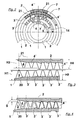
- Fig. 1 shows part of a dispersing device with two relative to each other in Circumferential direction movable complementary sets 1, 2, so together in Intervention that they can work together. They are arranged in relation to each other that everywhere there is a minimal distance between relatively moving surfaces is observed; this can advantageously be larger than 1 mm.
- the chosen one Representation in the form of a section in side view shows that radial the teeth 3, 4, 3 ', 4' belonging to the various sets from the inside out etc. alternate up to the outer teeth 3 ", 4".
- the tooth feet are too far predominantly in each case on a level E1 of a set 1 or E2 of second set 2. This allows the material flow in the radially outer part of the Develop sets particularly well and do not tend to get caught and / or Bake on.
- Deviations from this flat arrangement can, however Immediate central inlet area may be useful (rows of teeth with teeth 3 or 4).
- the teeth row of a set extends into the space between complementary set, with the intended operation of the device Clearances between complementary sets of teeth are maintained have to.
- the set 2 shown on the left belongs to the stator 6 and the one shown on the right Set 1 to rotor 5. This is held by a shaft 10 and in rotation transferred.
- the highly consistent paper pulp passes through the feed pipe 9 with the help a screw conveyor 12 centrally in the disperser.
- a substance is relatively tough, different from e.g. a pumpable paper fiber suspension, such as that in deflipers or Refiners is processed. It is first captured by the spinner cross 11 and then promoted in the trimmings.
- the radially innermost row of teeth belongs to the rotor assembly and the radially outermost to the stator set.
- the axis of rotation of the rotor 5 lies here horizontal, and the radial transport direction of the highly consistent paper pulp lies in vertical planes.
- the sets are housed in a housing 13.
- the set 2 belonging to the stator 6 can be moved in with the aid of a displacement device 8 Axial direction can be adjusted by a few millimeters. As already stated, can thereby the distance between the complementary sets 1 and 2 den Can be adjusted accordingly.
- the sets 1 and 2 designed such that they have larger axial distances radially on the inside than radially Outside. You can see here that e.g. on the inner tooth 3 between the tooth tip and axially opposite a clothing surface there is a distance a that is significantly larger than the distance c, which is on the radially last tooth 3 '' 'of the clothing 1 opposite set 2 forms.
- the axial distances b are also on the tooth flanks and d, which also change due to the adjustment process if they - as drawn here - are oblique to the axial direction. Therefore here are the Axial distances b radially inside larger than the axial distances d radially outside.
- axial distances on the tooth flanks do not always have to meet these criteria be designed. As a result of the slope there is already one on the flanks There is a larger adjustment range up to the contact of the counter surface than on the Tooth tips.
- Fig. 2 shows in supervision a Dispergergarnitursatz, so a rotor and one Stator assembly.
- the annular spaces 14 can be seen.
- the teeth 3, 3 ', 3 ", 4, 4 ', 4" (drawn cut) are arranged in annular rows and extend into the corresponding spaces 14 of the counter set. Of the Many teeth are shown only a few. Remain between adjacent teeth Tooth gaps 7 free for the flow of the fibrous material.
- the shape of the teeth depends according to the intended use of the set.
- the cross-section 21 is through Section is formed in the radial plane, a square, in particular a rectangle.
- the Cross sections 21 can be slightly rounded at the corners, e.g. for trimmings whose Tooth gaps 7 are already formed during casting. Teeth with such cross sections are generally ideal for dispersing highly consistent fiber.
- the set of fittings shown in Fig. 3 also consists of two sets 1 and 2, although are not engaged here, but are aligned with each other. I.e. you can by Movement on the axially directed allocation lines 21 in engagement in the disperger to be brought.
- These sets show a concrete practical example of Realization of the invention.
- the height H2 of the inner tooth 3 of the set 1 same as that of the three outer teeth 3 ', 3 ". The height is in each case above the measured back surface 20 of the set.
- the radially innermost tooth 3 of the set 1 as high as e.g. the teeth of the three outer ones Rows of teeth; nevertheless, the task can be solved because the base plate of the Counterpart 2 is thinner at this point.
- the set 2 belonging to the stator has two radially inner rows of teeth with a lower height H3 than the four further external rows of teeth that have the smaller height H4.
- this is an example which the inventive Design of the dispersing device clarifies.
- FIG. 5 two interlocking sets are drawn in somewhat more detail, without but to reveal all constructive features.
- the radially inner one is shown Area 17, a middle area 18 and the radially outer area 19.
- the middle 17, that is between the teeth 3 and 4 of the inner Rows of teeth and the teeth 3 "or 4" of the outermost rows of teeth can be "Intermediate solutions” can be selected when choosing the distances e or f. With that Values meant between those for the distances a, b, c and d already mentioned lie.
- the specifically determined wear behavior can be taken into account here.
- a centering collar 16 is used for exact centering of the clothing 1 belonging to the rotor provided, but not on the outside diameter of this set, so that there forms a radial projection.
- Such axial projections can be made of the same material as the set, e.g. without big extra effort to be cast on.
Landscapes
- Chemical & Material Sciences (AREA)
- Chemical Kinetics & Catalysis (AREA)
- Dispersion Chemistry (AREA)
- Paper (AREA)
- Crushing And Grinding (AREA)
Abstract
Description
- Fig. 1
- einen Teil einer erfindungsgemäßen Vorrichtung in geschnittener Seitenansicht;
- Fig. 2
- Aufsicht auf eine Garnitur;
- Fig. 3 und 4
- Teilansicht eines Garnitursatzes in zwei verschiedenen Positionen zueinander;
- Fig. 5
- eine Detailansicht zweier in Arbeitsstellung zueinander stehenden Garnituren.
Claims (18)
- Vorrichtung zur Dispergierung von hochkonsistentem Papierfaserstoff, die mindestens zwei Garnituren (1, 2,) enthält,dadurch gekennzeichnet, dass die Garnituren (1,2) so geformt sind, dass mindestens ein Teil der minimalen Axialabstände (a, b) zwischen den Garnituren (1, 2) im radial inneren Bereich der Garnituren (1, 2) signifikant größer ist als die minimalen Axialabstände (c, d) im radial äußeren Bereich.1.1 die jeweils eine im wesentlichen rotationssymmetrische Form haben und axial zueinander versetzt angeordnet sind,1.2 die in ringförmigen, zu ihrer Mitte konzentrischen Reihen angeordnete Zähne (3, 3', 3", 4, 4', 4") aufweisen, zwischen welchen sich Zahnlücken (7) befinden, die freie Querschnitte bilden, welche von dem zu behandelnden Faserstoff durchströmbar sind, wobei die Zahnfüße der radial äußeren Zähne (3', 3", 4', 4") einer Garnitur (1, 2) zum überwiegenden Anteil jeweils auf einer Ebene (E1, E2) liegen,1.3 die zwischen den Zahnreihen ringförmige Zwischenräume (14) aufweisen,1.4 die so zueinander positioniert sind, dass mindestens eine Zahnreihe einer Garnitur (1,2) in einen ringförmigen Zwischenraum (14) der anderen, komplementären Garnitur (2,1) hineinreicht,1.5 wobei wenigstens eine Garnitur (1) relativ zur anderen in Umfangsrichtung bewegbar ist,1.6 wobei die Garnituren (1, 2) zu Einstellungszwecken relativ zueinander in Axialrichtung bewegbar sind,
- Vorrichtung nach Anspruch 1,
dadurch gekennzeichnet, dass die Zahnfüße von mindestens 80 % der radial äußeren Zähne (3', 3", 4', 4") einer Garnitur (1, 2) jeweils auf einer Ebene (E1, E2) liegen. - Vorrichtung nach Anspruch 1 oder 2,
dadurch gekennzeichnet, dass eine Garnitur (2) zu einem feststehenden Stator (6) gehört und die komplementäre Garnitur (1) zu einem antreibbaren Rotor (5). - Vorrichtung nach Anspruch 1, 2 oder 3,
dadurch gekennzeichnet, dass die minimalen Axialabstände (a) an den Zahnspitzen im radial inneren Bereich der Garnituren (1,2) signifikant größer sind als die minimalen Axialabstände (c) an den Zahnspitzen im radial äußeren Bereich. - Vorrichtung nach Anspruch 2, 3 oder 4,
dadurch gekennzeichnet, dass an mindestens zwei, höchstens fünf der radial inneren Zahnreihen der zum Rotor (5) gehörenden Garnitur (1) die minimalen Axialabstände (a) an den Zahnspitzen signifikant größer sind als die minimalen Axialabstände (b) an den übrigen Zahnreihen dieser Garnitur (1). - Vorrichtung nach Anspruch 4 oder 5,
dadurch gekennzeichnet, dass die minimalen Axialabstände an den Zahnflanken (d, f) in unterschiedlichen Zahnreihen im wesentlichen gleich sind, sofern die Zähne (3', 3", 4', 4") auf einer Ebene (E1, E2) fußen. - Vorrichtung nach einem der voranstehenden Ansprüche,
dadurch gekennzeichnet, dass die minimalen Axialabstände (b) an den Zahnflanken im radial inneren Bereich der Garnituren (1, 2) signifikant größer sind als die minimalen Axialabstände (d) an den Zahnflanken im radial äußeren Bereich. - Vorrichtung nach Anspruch 3,
dadurch gekennzeichnet, dass an mindestens zwei, höchstens fünf der radial inneren Zahnreihen der zum Rotor (5) gehörenden Garnitur (1) die minimalen Axialabstände (b) an den Zahnflanken signifikant größer sind als die minimalen Axialabstände (d, f) an den übrigen Zahnreihen dieser Garnitur (1). - Vorrichtung nach Anspruch 3,
dadurch gekennzeichnet, dass mindestens zwei, höchstens vier der radial inneren Zahnreihen der zum Stator (6) gehörenden Garnitur (2) eine geringere Zahnhöhe, gemessen über der Auflagefläche (20) der Garnitur (2), aufweisen als die übrigen Zahnreihen dieser Garnitur (2). - Vorrichtung Anspruch 3,
dadurch gekennzeichnet, dass mindestens zwei, höchstens vier der radial inneren Zahnreihen der zum Rotor (5) gehörenden Garnitur (1) eine geringere Zahnhöhe, gemessen über der Auflagefläche (20) der Garnitur (1), aufweisen als die übrigen Zahnreihen des Rotors. - Vorrichtung nach einem der voranstehenden Ansprüche,
dadurch gekennzeichnet, dass die Differenz der bezeichneten minimalen Axialabstände (a, b, c, d) mindestens 2 mm beträgt. - Vorrichtung nach Anspruch 11,
dadurch gekennzeichnet, dass die Differenz der bezeichneten minimalen Axialabstände (a, b, c, d) mindestens 5 mm beträgt. - Vorrichtung nach einem der voranstehenden Ansprüche,
dadurch gekennzeichnet, dass die Differenz der bezeichneten minimalen Axialabstände (a, b, c, d) mindestens 10 % der axialen Zahnhöhe beträgt. - Vorrichtung nach einem der voranstehenden Ansprüche,
dadurch gekennzeichnet, dass der in radialer Ebene liegende Querschnitt (21) der Zähne (3, 3', 3", 4, 4', 4") eine Viereckform hat. - Vorrichtung nach Anspruch 14,
dadurch gekennzeichnet, dass der in radialer Ebene liegende Querschnitt (21) der Zähne (3,3', 3", 4, 4', 4") eine Rechteckform hat. - Vorrichtung nach Anspruch 14 oder 15,
dadurch gekennzeichnet, dass die Querschnitte (21) an den Kanten abgerundet sind. - Vorrichtung nach einem der voranstehenden Ansprüche,
dadurch gekennzelchnet,
dass der minimale Abstand, den die Zähne (3, 3', 3", 4, 4', 4") der relativ zueinander bewegbaren Garnituren voneinander haben, mindestens 1 mm beträgt. - Dispergergarnitur-Satz zur Verwendung in einer Dispergiervorrichtung gemäß einem der voranstehenden Ansprüche, welcher mindestens aus zwei Garnituren (1, 2), und zwar einer Rotor- und einer Statorgarnitur, besteht,
dadurch gekennzeichnet, dass die Garnituren (1, 2), wenn sie in die bestimmungsgemäße Gebrauchslage zueinander gebracht sind, an den Zahnspitzen im radial inneren Bereich solche Axialabstände (a) zur gegenüberliegenden Garnitur aufweisen, die signifikant größer sind als die Axialabstände (b) an den Zahnspitzen im radial äußeren Bereich der Garnituren (1, 2).
Applications Claiming Priority (2)
| Application Number | Priority Date | Filing Date | Title |
|---|---|---|---|
| DE10017899A DE10017899A1 (de) | 2000-04-11 | 2000-04-11 | Vorrichtung zur Dispergierung von hochkonsistentem Papierfaserstoff sowie Garnituren für diese Vorrichtung |
| DE10017899 | 2000-04-11 |
Publications (2)
| Publication Number | Publication Date |
|---|---|
| EP1147806A1 true EP1147806A1 (de) | 2001-10-24 |
| EP1147806B1 EP1147806B1 (de) | 2004-07-28 |
Family
ID=7638308
Family Applications (1)
| Application Number | Title | Priority Date | Filing Date |
|---|---|---|---|
| EP01104248A Expired - Lifetime EP1147806B1 (de) | 2000-04-11 | 2001-02-22 | Vorrichtung zur Dispergierung von hochkonsistentem Papierfaserstoff sowie Garnituren für diese Vorrichtung |
Country Status (3)
| Country | Link |
|---|---|
| EP (1) | EP1147806B1 (de) |
| AT (1) | ATE271915T1 (de) |
| DE (2) | DE10017899A1 (de) |
Cited By (4)
| Publication number | Priority date | Publication date | Assignee | Title |
|---|---|---|---|---|
| EP1749922A1 (de) * | 2005-08-04 | 2007-02-07 | Andritz AG | Platte oder Plattensegment sowie Vorrichtung mit derartigen Platten oder Plattensegmenten |
| EP1806451A1 (de) * | 2006-01-09 | 2007-07-11 | Andritz Inc. | Mahlscheibe mit V-förmigen Zähne und Verfahren zur Raffinierung |
| WO2010057725A1 (de) * | 2008-11-22 | 2010-05-27 | Voith Patent Gmbh | Verfahren zur behandlung einer fasersuspension, insbesondere zum auflösen von stippen sowie vorrichtung zur durchführung des verfahrens |
| WO2020151951A1 (de) * | 2019-01-25 | 2020-07-30 | Voith Patent Gmbh | Verfahren zur steuerung einer vorrichtung zur behandlung von hochkonsistem faserstoff |
Families Citing this family (1)
| Publication number | Priority date | Publication date | Assignee | Title |
|---|---|---|---|---|
| JP7551218B2 (ja) * | 2021-06-18 | 2024-09-17 | エルジー・ケム・リミテッド | 高吸水性樹脂の含水ゲル微粒化装置 |
Citations (7)
| Publication number | Priority date | Publication date | Assignee | Title |
|---|---|---|---|---|
| GB763823A (en) * | 1955-01-31 | 1956-12-19 | Jackson And Church Company | Method for treating a fibrous material |
| FR1194715A (fr) * | 1958-04-15 | 1959-11-12 | Disperseur homogénéiseur de produits en phase fluide ou visqueuse | |
| FR2148488A1 (de) * | 1971-08-06 | 1973-03-23 | Morat Gmbh Franz | |
| DE2931275A1 (de) * | 1978-08-07 | 1980-02-28 | Berggren Torsten L | Verfahren und vorrichtung zum mahlen von fasertrueben |
| FR2494734A1 (fr) * | 1980-11-25 | 1982-05-28 | Escher Wyss Gmbh | Dispositif de dispersion pour l'elaboration d'une matiere a base de vieux papiers |
| SU1238782A1 (ru) * | 1982-12-08 | 1986-06-23 | Проектно-Конструкторское Бюро Главного Управления Локомотивного Хозяйства Мпс Ссср | Дисковый гомогенизатор |
| EP0751254A1 (de) * | 1995-06-29 | 1997-01-02 | Voith Sulzer Stoffaufbereitung GmbH | Vorrichtung zur geregelten Dispergierbehandlung von hochkonsistentem Faserstoff |
-
2000
- 2000-04-11 DE DE10017899A patent/DE10017899A1/de not_active Withdrawn
-
2001
- 2001-02-22 AT AT01104248T patent/ATE271915T1/de active
- 2001-02-22 EP EP01104248A patent/EP1147806B1/de not_active Expired - Lifetime
- 2001-02-22 DE DE50102956T patent/DE50102956D1/de not_active Expired - Lifetime
Patent Citations (7)
| Publication number | Priority date | Publication date | Assignee | Title |
|---|---|---|---|---|
| GB763823A (en) * | 1955-01-31 | 1956-12-19 | Jackson And Church Company | Method for treating a fibrous material |
| FR1194715A (fr) * | 1958-04-15 | 1959-11-12 | Disperseur homogénéiseur de produits en phase fluide ou visqueuse | |
| FR2148488A1 (de) * | 1971-08-06 | 1973-03-23 | Morat Gmbh Franz | |
| DE2931275A1 (de) * | 1978-08-07 | 1980-02-28 | Berggren Torsten L | Verfahren und vorrichtung zum mahlen von fasertrueben |
| FR2494734A1 (fr) * | 1980-11-25 | 1982-05-28 | Escher Wyss Gmbh | Dispositif de dispersion pour l'elaboration d'une matiere a base de vieux papiers |
| SU1238782A1 (ru) * | 1982-12-08 | 1986-06-23 | Проектно-Конструкторское Бюро Главного Управления Локомотивного Хозяйства Мпс Ссср | Дисковый гомогенизатор |
| EP0751254A1 (de) * | 1995-06-29 | 1997-01-02 | Voith Sulzer Stoffaufbereitung GmbH | Vorrichtung zur geregelten Dispergierbehandlung von hochkonsistentem Faserstoff |
Cited By (8)
| Publication number | Priority date | Publication date | Assignee | Title |
|---|---|---|---|---|
| EP1749922A1 (de) * | 2005-08-04 | 2007-02-07 | Andritz AG | Platte oder Plattensegment sowie Vorrichtung mit derartigen Platten oder Plattensegmenten |
| EP1806451A1 (de) * | 2006-01-09 | 2007-07-11 | Andritz Inc. | Mahlscheibe mit V-förmigen Zähne und Verfahren zur Raffinierung |
| US7478773B2 (en) | 2006-01-09 | 2009-01-20 | Andritz Inc. | Tooth refiner plates having V-shaped teeth and refining method |
| EP2476804A1 (de) * | 2006-01-09 | 2012-07-18 | Andritz Inc. | Zahndispergierplatten mit V-förmigen Zähnen |
| WO2010057725A1 (de) * | 2008-11-22 | 2010-05-27 | Voith Patent Gmbh | Verfahren zur behandlung einer fasersuspension, insbesondere zum auflösen von stippen sowie vorrichtung zur durchführung des verfahrens |
| WO2020151951A1 (de) * | 2019-01-25 | 2020-07-30 | Voith Patent Gmbh | Verfahren zur steuerung einer vorrichtung zur behandlung von hochkonsistem faserstoff |
| CN113330159A (zh) * | 2019-01-25 | 2021-08-31 | 福伊特专利有限公司 | 控制用于处理高稠度的纤维材料的装置的方法 |
| US12043959B2 (en) | 2019-01-25 | 2024-07-23 | Voith Patent Gmbh | Method for controlling a device for treating high-consistency pulp |
Also Published As
| Publication number | Publication date |
|---|---|
| EP1147806B1 (de) | 2004-07-28 |
| ATE271915T1 (de) | 2004-08-15 |
| DE50102956D1 (de) | 2004-09-02 |
| DE10017899A1 (de) | 2001-10-18 |
Similar Documents
| Publication | Publication Date | Title |
|---|---|---|
| DE19523704C2 (de) | Vorrichtung zur mechanischen Behandlung von hochkonsistentem Faserstoff | |
| EP0773316B1 (de) | Vorrichtung zur Behandlung von hochkonsistentem Faserstoff | |
| EP0773317B1 (de) | Vorrichtung und Behandlungsmaschine zur mechanischen Behandlung von hochkonsistentem Faserstoff | |
| EP3398683B1 (de) | Behandlungsgarnitur zur behandlung von wässrig suspendiertem faserstoff | |
| EP1147806B1 (de) | Vorrichtung zur Dispergierung von hochkonsistentem Papierfaserstoff sowie Garnituren für diese Vorrichtung | |
| EP0731210B1 (de) | Mahlmaschine und Mahlwerkzeug zum Mahlen von suspendiertem Faserstoffmaterial | |
| WO2009097963A2 (de) | Vorrichtung zur bearbeitung von faserstoff für die papier- oder kartonerzeugung | |
| EP0931584B1 (de) | Vorrichtung zum Dispergieren von hochkonsistentem Altpapier | |
| AT502541B1 (de) | Platte oder plattensegment sowie vorrichtung mit derartigen platten oder plattensegmenten | |
| EP1147804B1 (de) | Vorrichtung zur Dispergierung von hochkonsistentem Papierfaserstoff | |
| DE1461012C3 (de) | Vonchtung zum Zerfasern von Papierstoff | |
| WO2011069703A2 (de) | Disperger iii | |
| EP1146168B1 (de) | Vorrichtung zur Dispergierung von hochkonsistentem Papierfaserstoff | |
| DE1180349B (de) | Vorrichtung zur Bearbeitung einer in Partikel- oder Suspensionsform befindlichen Materialmasse | |
| DE212010000171U1 (de) | Disperger IV | |
| DE202009018666U1 (de) | Disperger IV | |
| DE29800987U1 (de) | Vorrichtung zur mechanischen Behandlung von hochkonsistentem Faserstoff | |
| DE20006632U1 (de) | Vorrichtung zur Dispergierung von hochkonsistentem Papierfaserstoff | |
| DE102009047631A1 (de) | Disperger II | |
| DE1260289B (de) | Stoffmuehle zum Zerkleinern von Faserstoffen | |
| WO2010057725A1 (de) | Verfahren zur behandlung einer fasersuspension, insbesondere zum auflösen von stippen sowie vorrichtung zur durchführung des verfahrens |
Legal Events
| Date | Code | Title | Description |
|---|---|---|---|
| PUAI | Public reference made under article 153(3) epc to a published international application that has entered the european phase |
Free format text: ORIGINAL CODE: 0009012 |
|
| AK | Designated contracting states |
Kind code of ref document: A1 Designated state(s): AT BE CH CY DE DK ES FI FR GB GR IE IT LI LU MC NL PT SE TR Kind code of ref document: A1 Designated state(s): AT DE FI FR GB SE |
|
| AX | Request for extension of the european patent |
Free format text: AL;LT;LV;MK;RO;SI |
|
| 17P | Request for examination filed |
Effective date: 20020424 |
|
| AKX | Designation fees paid |
Free format text: AT DE FI FR GB SE |
|
| 17Q | First examination report despatched |
Effective date: 20030828 |
|
| GRAP | Despatch of communication of intention to grant a patent |
Free format text: ORIGINAL CODE: EPIDOSNIGR1 |
|
| GRAS | Grant fee paid |
Free format text: ORIGINAL CODE: EPIDOSNIGR3 |
|
| GRAA | (expected) grant |
Free format text: ORIGINAL CODE: 0009210 |
|
| AK | Designated contracting states |
Kind code of ref document: B1 Designated state(s): AT DE FI FR GB SE |
|
| REG | Reference to a national code |
Ref country code: GB Ref legal event code: FG4D Free format text: NOT ENGLISH |
|
| REG | Reference to a national code |
Ref country code: SE Ref legal event code: TRGR |
|
| GBT | Gb: translation of ep patent filed (gb section 77(6)(a)/1977) |
Effective date: 20040728 |
|
| REF | Corresponds to: |
Ref document number: 50102956 Country of ref document: DE Date of ref document: 20040902 Kind code of ref document: P |
|
| ET | Fr: translation filed | ||
| PLBE | No opposition filed within time limit |
Free format text: ORIGINAL CODE: 0009261 |
|
| STAA | Information on the status of an ep patent application or granted ep patent |
Free format text: STATUS: NO OPPOSITION FILED WITHIN TIME LIMIT |
|
| 26N | No opposition filed |
Effective date: 20050429 |
|
| PGFP | Annual fee paid to national office [announced via postgrant information from national office to epo] |
Ref country code: FR Payment date: 20120227 Year of fee payment: 12 |
|
| PGFP | Annual fee paid to national office [announced via postgrant information from national office to epo] |
Ref country code: DE Payment date: 20120221 Year of fee payment: 12 |
|
| PGFP | Annual fee paid to national office [announced via postgrant information from national office to epo] |
Ref country code: SE Payment date: 20120217 Year of fee payment: 12 Ref country code: GB Payment date: 20120221 Year of fee payment: 12 Ref country code: FI Payment date: 20120213 Year of fee payment: 12 |
|
| PGFP | Annual fee paid to national office [announced via postgrant information from national office to epo] |
Ref country code: AT Payment date: 20120213 Year of fee payment: 12 |
|
| REG | Reference to a national code |
Ref country code: SE Ref legal event code: EUG |
|
| REG | Reference to a national code |
Ref country code: AT Ref legal event code: MM01 Ref document number: 271915 Country of ref document: AT Kind code of ref document: T Effective date: 20130228 |
|
| GBPC | Gb: european patent ceased through non-payment of renewal fee |
Effective date: 20130222 |
|
| PG25 | Lapsed in a contracting state [announced via postgrant information from national office to epo] |
Ref country code: AT Free format text: LAPSE BECAUSE OF NON-PAYMENT OF DUE FEES Effective date: 20130228 Ref country code: FI Free format text: LAPSE BECAUSE OF NON-PAYMENT OF DUE FEES Effective date: 20130222 Ref country code: SE Free format text: LAPSE BECAUSE OF NON-PAYMENT OF DUE FEES Effective date: 20130223 |
|
| REG | Reference to a national code |
Ref country code: FR Ref legal event code: ST Effective date: 20131031 |
|
| REG | Reference to a national code |
Ref country code: DE Ref legal event code: R119 Ref document number: 50102956 Country of ref document: DE Effective date: 20130903 |
|
| PG25 | Lapsed in a contracting state [announced via postgrant information from national office to epo] |
Ref country code: GB Free format text: LAPSE BECAUSE OF NON-PAYMENT OF DUE FEES Effective date: 20130222 Ref country code: DE Free format text: LAPSE BECAUSE OF NON-PAYMENT OF DUE FEES Effective date: 20130903 Ref country code: FR Free format text: LAPSE BECAUSE OF NON-PAYMENT OF DUE FEES Effective date: 20130228 |