EP1146670A2 - Koppelelement zum Anschluss eines elektrischen Geräts an einem optischen Datenbus - Google Patents
Koppelelement zum Anschluss eines elektrischen Geräts an einem optischen Datenbus Download PDFInfo
- Publication number
- EP1146670A2 EP1146670A2 EP01107332A EP01107332A EP1146670A2 EP 1146670 A2 EP1146670 A2 EP 1146670A2 EP 01107332 A EP01107332 A EP 01107332A EP 01107332 A EP01107332 A EP 01107332A EP 1146670 A2 EP1146670 A2 EP 1146670A2
- Authority
- EP
- European Patent Office
- Prior art keywords
- coupling element
- data bus
- optical
- electrical
- converters
- Prior art date
- Legal status (The legal status is an assumption and is not a legal conclusion. Google has not performed a legal analysis and makes no representation as to the accuracy of the status listed.)
- Withdrawn
Links
Images
Classifications
-
- H—ELECTRICITY
- H04—ELECTRIC COMMUNICATION TECHNIQUE
- H04B—TRANSMISSION
- H04B10/00—Transmission systems employing electromagnetic waves other than radio-waves, e.g. infrared, visible or ultraviolet light, or employing corpuscular radiation, e.g. quantum communication
- H04B10/29—Repeaters
Definitions
- the invention relates to a coupling element for connecting an electrical Device on an optical data bus with unidirectional transmission.
- each device Receiver (Optln) as part of an optoelectric converter and a optical transmitter (OptOut) as part of an electro-optical converter.
- the two converters are used for the data telegrams arriving from the data bus to the device or the outgoing data telegrams to be transmitted to the data bus.
- each of the two converters there must be an optical interface between each the data bus and the electrical device. This is to be designed for complex mating cycles through complex design measures, because the devices are often unplugged and then plugged in again (Service). This interface is also sensitive to contamination and other environmental influences (chemicals, fittings ). You must go through elaborate mechanical constructions are protected.
- optical elements inside the electrical Devices are placed.
- the optics are sensitive to high temperatures, as they arise inside many devices.
- the devices are elaborate Measures to cool (cooling structures, fans ). They are also optical elements not equally suitable for automatic manufacturing processes. It has to be complex and expensive to process Special processes are run. If the supply voltage drops Device or if the device is not plugged in or not plugged in correctly, in particular in the case of optical ring buses, the entire bus is paralyzed as an incoming one optical signal no longer to the next participant in the Bus can be transported.
- the invention has for its object a coupling element of the beginning to create mentioned type that is simple and robust to use and that can be used in particular in heavily used environments. It should be particularly suitable for the application of a motor vehicle.
- the invention solves this problem by the specified in claim 1 Characteristics.
- optical elements in particular the optical receiver and the optical Transmitters are integrated in the coupling element. It arises "active optical coupling element". If the coupling element is disconnected from the device, becomes the electrical output signal of the electro-optical converter led directly to the electro-optical converter. Is the coupling element on If the device is plugged in, the electrical connection between the two converters is switched on disconnected the (mechanical or electronic) switch. The output signal of the optoelectric converter is in the device for processing guided. The electrical output signal of the device is via the electro-optical converter on the data bus.
- the power supply of the two converters is advantageously independent whether the coupling element is arranged on the device.
- the electrical Connection lines for this end like the optical fibers in the coupling element.
- Those for the power supply of the two converters may also be required necessary elements, e.g. Adaptation elements, amplifiers, etc. can also be arranged in the coupling element. This results in an integrated Power supply device for the two converters.
- the power supply device can have separate connection contacts feature.
- the coupling element can be arranged for the device provide a power supply (e.g. + 12V and Gnd) via the coupling element.
- the two data bus lines connected to the converters can be used with these are inextricably linked. They can be cast in. Thereby the risk of contamination is further reduced.
- the electrical connection between the two transducers can be made using a Proximity switch can be switched, which responds when the device is present.
- Proximity switch can be switched, which responds when the device is present.
- the active optical coupling element advantageously also contains one Signal conditioning unit that the output signal of the optoelectric Converter regenerated so that an ideal pulse-pause ratio with less Pulse width distortion arises.
- Any angle of outlets of the optical cables can easily be realize because the required bend on the electrical side and thus can be realized with any small bending radius.
- the invention realizes an increased level of security.
- the operation even a ring bus does not become unplugged more interrupted because the signal in the coupling element is short-circuited and the incoming optical signal regenerates and goes to the next one Device is retransmitted.
- the invention is further explained on the basis of the drawing.
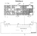
- the only figure shows schematically the structure of a coupling element according to the invention for connecting an electrical device to an optical data bus.
- a coupling element 1 is used to connect an electrical device 2 to a Data bus 3 with unidirectional transmission.
- the data bus 3 is excerpted shown and has two optical fibers 4 and 5, which for Guide coupling element 1 (4) or move away from it (5).
- the coupling element 1 has a housing 6 in which the optical fibers 4 and 5 are cast, further an optoelectric converter 7, on which the Optical fiber 4 is connected, and an electro-optical converter 8, to which the optical fiber 5 is optically connected.
- switchable electrical connection between the two changes 11, which is open when the device 2 is connected and when not connected Device is closed.
- the switchable electrical connection 11 contains a proximity switch, which then responds and the connection 11 breaks.
- a signal processing unit is located within the coupling element 1 13, the signal of the electrical data output of the converter 7 so regenerates that an ideal pulse-pause ratio with low pulse width distortion arises.
- device 2 When coupling element 1 is connected, device 2 is connected to the data bus connected. It receives the first incoming optical telegrams electrically converted via the converter 7 and via the signal processing unit 13 deals with a signal processing stage 15 and passes it on the converter 8 as an optical telegram to the data bus.
- the device 2 is not connected to the Data bus connected.
- the first incoming optical telegrams are converted electrically via the converter 7 and via the signal processing unit 13 treated to the transducer 8, which they as optical Forwards the telegram to the data bus.
- the entire optics are realized in the coupling element. There is no optical Interface more that is exposed to several mating cycles. Is stuck on the electrical side. This is a standard problem that is fine today is mastered.
- the entire sensitive optic is encapsulated in the coupling element. Environmental influences such as pollution, chemicals, etc. are completely excluded. In the processing process, e.g. Production, Customer service enters the optical character of data transmission (via the optical data bus).
- Handling is again based on well-known and mastered electrical Interfaces returned.
- the temperature sensitive optics is from the hot interior of the devices removed, so that no unusual Cooling measures need to be taken more. Elaborate processing processes the optics in device manufacturing are eliminated.
Landscapes
- Physics & Mathematics (AREA)
- Electromagnetism (AREA)
- Engineering & Computer Science (AREA)
- Computer Networks & Wireless Communication (AREA)
- Signal Processing (AREA)
- Optical Communication System (AREA)
- Optical Couplings Of Light Guides (AREA)
- Dc Digital Transmission (AREA)
Abstract
Description
Claims (6)
- Koppelelement zum Anschluß eines elektrischen Geräts an einem optischen Datenbus mit unidirektionaler Übertragung, gekennzeichnet durch folgende Merkmale: ein Gehäuse enthält einen optoelektrischen Wandler, an dem eine Eingangs-Datenbusleitung optisch angeschlossen ist, und einen elektrooptischen Wandler, an dem eine Ausgangs-Datenbusleitung optisch angeschlossen ist, ferner an der Aussenseite zwei elektrische Kontakte, über die die beiden Wandler mit dem Gerät elektrisch anschließbar sind sowie eine schaltbare elektrische Verbindung zwischen den beiden Wandlern, die bei angeschlossenem Gerät offen und bei nicht angeschlossenem Gerät geschlossen ist.
- Koppelelement nach Anspruch 1, dadurch gekennzeichnet, daß es eine integrierte Stromversorgungseinrichtung für die beiden Wandler enthält.
- Koppelelement nach Anspruch 2, dadurch gekennzeichnet, daß es separate Anschlußkontakte für die Stromversorgung des angeschlossenen Geräts besitzt.
- Koppelelement nach einem der Ansprüche 1 bis 3, dadurch gekennzeichnet, daß die beiden Datenbusleitungen unlösbar verbunden sind.
- Koppelelement nach Anspruch 4, dadurch gekennzeichnet, daß die beiden Datenbusleitungen eingegossen sind.
- Koppelelement nach einem der Ansprüche 1 bis 5, dadurch gekennzeichnet, daß die elektrische Verbindung zwischen den beiden Wandlern mittels eines Näherungsschalters schaltbar ist.
Applications Claiming Priority (2)
| Application Number | Priority Date | Filing Date | Title |
|---|---|---|---|
| DE10018719A DE10018719A1 (de) | 2000-04-15 | 2000-04-15 | Koppelelement zum Anschluß eines elektrischen Geräts an einem optischen Datenbus |
| DE10018719 | 2000-04-15 |
Publications (2)
| Publication Number | Publication Date |
|---|---|
| EP1146670A2 true EP1146670A2 (de) | 2001-10-17 |
| EP1146670A3 EP1146670A3 (de) | 2004-03-10 |
Family
ID=7638856
Family Applications (1)
| Application Number | Title | Priority Date | Filing Date |
|---|---|---|---|
| EP01107332A Withdrawn EP1146670A3 (de) | 2000-04-15 | 2001-03-24 | Koppelelement zum Anschluss eines elektrischen Geräts an einem optischen Datenbus |
Country Status (4)
| Country | Link |
|---|---|
| US (1) | US6450700B2 (de) |
| EP (1) | EP1146670A3 (de) |
| JP (1) | JP2001356848A (de) |
| DE (1) | DE10018719A1 (de) |
Families Citing this family (1)
| Publication number | Priority date | Publication date | Assignee | Title |
|---|---|---|---|---|
| DE10357416A1 (de) * | 2003-12-03 | 2005-07-14 | Siemens Ag | Anordnung zum Verbinden eines Lichtwellenleiters mit einem mikroprozessorgesteuerten elektrischen Gerät |
Family Cites Families (9)
| Publication number | Priority date | Publication date | Assignee | Title |
|---|---|---|---|---|
| DE3336237A1 (de) * | 1983-10-05 | 1985-04-18 | Siemens AG, 1000 Berlin und 8000 München | Roentgendiagnostikanlage mit einer mehrzahl von anlagenkomponenten |
| FR2598582A1 (fr) * | 1986-05-06 | 1987-11-13 | Thomson Cgr | Installation de radiologie a plusieurs appareils commandes selon une boucle avec un dispositif de court-circuit pour chaque appareil |
| US5016966A (en) * | 1990-04-12 | 1991-05-21 | Amp Incorporated | Asymmetic optical fiber tap |
| US5131061A (en) * | 1991-02-13 | 1992-07-14 | International Business Machines Corp. | Modular active fiber optic coupler system |
| FR2690802B1 (fr) * | 1992-04-29 | 1994-08-19 | Cit Alcatel | Dispositif de transduction optoélectronique pour équipement de terminaison de liaison optique, et application à divers types de liaisons optiques. |
| US5475778A (en) * | 1993-10-21 | 1995-12-12 | Motorola, Inc. | Smart optical coupler and smart optical coupler system |
| JPH088818A (ja) * | 1994-06-17 | 1996-01-12 | Hitachi Cable Ltd | 電子回路一体型光送受信モジュール |
| US5615292A (en) * | 1995-02-10 | 1997-03-25 | Beckwith; Robert W. | Fiber optic terminator with electrical input/output |
| US6229712B1 (en) * | 1999-03-31 | 2001-05-08 | International Business Machines Corporation | Printed circuit board for coupling surface mounted optoelectric semiconductor devices |
-
2000
- 2000-04-15 DE DE10018719A patent/DE10018719A1/de not_active Withdrawn
-
2001
- 2001-03-24 EP EP01107332A patent/EP1146670A3/de not_active Withdrawn
- 2001-03-27 US US09/817,174 patent/US6450700B2/en not_active Expired - Fee Related
- 2001-04-12 JP JP2001114149A patent/JP2001356848A/ja active Pending
Also Published As
| Publication number | Publication date |
|---|---|
| DE10018719A1 (de) | 2001-10-18 |
| US6450700B2 (en) | 2002-09-17 |
| JP2001356848A (ja) | 2001-12-26 |
| US20010041032A1 (en) | 2001-11-15 |
| EP1146670A3 (de) | 2004-03-10 |
Similar Documents
| Publication | Publication Date | Title |
|---|---|---|
| EP3523816B1 (de) | Vorrichtung zur kontaktlosen induktiven energieübertragung und betriebsverfahren für eine derartige vorrichtung | |
| DE102012212254B3 (de) | Verbinder zur leitungsungebundenen Signalübertragung | |
| DE102008058090A1 (de) | Ein-/Ausgabemodul für ein Automatisierungsgerät | |
| DE202018106353U1 (de) | Steckadapter zum Andocken an ein Magnetventil | |
| DE102018109307B3 (de) | 7Kommunikationssystem der Automatisierungs- und Prozesstechnik sowie Y-Weicheneinheit für ein solches Kommunikationssystem | |
| DE112018007530T5 (de) | Hot-Swap-fähiges Switch-Gehäuse ohne Kabelberührung | |
| EP1199546B1 (de) | Modulares Mess-System | |
| EP1146670A2 (de) | Koppelelement zum Anschluss eines elektrischen Geräts an einem optischen Datenbus | |
| DE102004017262A1 (de) | Konfigurierbare Kommunikationsmodule und Verfahren zur Herstellung derselben | |
| EP3097751B1 (de) | Verbindungsadaptersystem der steuerungstechnik | |
| WO2013083835A1 (de) | Verfahren zur ansteuerung einer mehrfarben-signalanordnung sowie mehrfarben-signalanordnung | |
| CH674281A5 (de) | ||
| EP1573211B1 (de) | Vorrichtung zur zustandsdiagnose einer fluidtechnischen komponente, insbesondere eines fluidikzylinders | |
| DE102011015587A1 (de) | Schaltvorrichtung | |
| DE102018107150A1 (de) | Getriebe, Motor-Getriebe-Kombination und Welle-Getriebe-Kombination | |
| DE4228733A1 (de) | Teilnehmersystem mit mehreren durch elektrische Geräte gebildeten Teilnehmern | |
| WO2020058173A1 (de) | Ladesteckverbinder zur kopplung mit einer korrespondierenden verbindungsvorrichtung und zur übertragung elektrischer energie sowie ladeeinrichtung zur abgabe elektrischer energie an einen empfänger elektrischer energie | |
| EP1943744B1 (de) | Gerät zur aufnahme eines moduls mit berührungsloser übertragung von energie und/oder daten | |
| EP0442046B1 (de) | Anschlusseinheit für die Hausleittechnik | |
| DE19625997A1 (de) | Vorrichtung zur Ansteuerung von Elementen wenigstens einer Maschine, insbesondere einer Werkzeugmaschine | |
| DE102024119915A1 (de) | Stellantrieb und Baugruppe | |
| DE202009015718U1 (de) | Steckvorrichtung mit einem Adapter-Übergehäuse | |
| DE3732740A1 (de) | Anordnung mit einer zentralen steuereinheit und mehreren teilnehmern | |
| EP1076381B1 (de) | Schalt-/Anzeigegerät der Steuerungstechnik | |
| DE3733018B4 (de) | Optokoppler |
Legal Events
| Date | Code | Title | Description |
|---|---|---|---|
| PUAI | Public reference made under article 153(3) epc to a published international application that has entered the european phase |
Free format text: ORIGINAL CODE: 0009012 |
|
| AK | Designated contracting states |
Kind code of ref document: A2 Designated state(s): AT BE CH CY DE DK ES FI FR GB GR IE IT LI LU MC NL PT SE TR |
|
| AX | Request for extension of the european patent |
Free format text: AL;LT;LV;MK;RO;SI |
|
| PUAL | Search report despatched |
Free format text: ORIGINAL CODE: 0009013 |
|
| AK | Designated contracting states |
Kind code of ref document: A3 Designated state(s): AT BE CH CY DE DK ES FI FR GB GR IE IT LI LU MC NL PT SE TR |
|
| AX | Request for extension of the european patent |
Extension state: AL LT LV MK RO SI |
|
| RIC1 | Information provided on ipc code assigned before grant |
Ipc: 7H 04B 10/213 B Ipc: 7H 04B 10/16 A |
|
| 17P | Request for examination filed |
Effective date: 20040320 |
|
| AKX | Designation fees paid |
Designated state(s): DE ES FR GB IT SE |
|
| 17Q | First examination report despatched |
Effective date: 20071129 |
|
| STAA | Information on the status of an ep patent application or granted ep patent |
Free format text: STATUS: THE APPLICATION IS DEEMED TO BE WITHDRAWN |
|
| 18D | Application deemed to be withdrawn |
Effective date: 20080410 |