EP1146209A2 - Ventilatorantrieb - Google Patents
Ventilatorantrieb Download PDFInfo
- Publication number
- EP1146209A2 EP1146209A2 EP01106768A EP01106768A EP1146209A2 EP 1146209 A2 EP1146209 A2 EP 1146209A2 EP 01106768 A EP01106768 A EP 01106768A EP 01106768 A EP01106768 A EP 01106768A EP 1146209 A2 EP1146209 A2 EP 1146209A2
- Authority
- EP
- European Patent Office
- Prior art keywords
- fan
- cooling system
- drive
- rear wall
- tensioning
- Prior art date
- Legal status (The legal status is an assumption and is not a legal conclusion. Google has not performed a legal analysis and makes no representation as to the accuracy of the status listed.)
- Granted
Links
- 238000001816 cooling Methods 0.000 claims abstract description 36
- 230000008878 coupling Effects 0.000 claims description 3
- 238000010168 coupling process Methods 0.000 claims description 3
- 238000005859 coupling reaction Methods 0.000 claims description 3
- 238000010276 construction Methods 0.000 description 5
- 229910052782 aluminium Inorganic materials 0.000 description 4
- XAGFODPZIPBFFR-UHFFFAOYSA-N aluminium Chemical compound [Al] XAGFODPZIPBFFR-UHFFFAOYSA-N 0.000 description 4
- 238000009434 installation Methods 0.000 description 2
- 238000012423 maintenance Methods 0.000 description 2
- 239000011324 bead Substances 0.000 description 1
- 230000015572 biosynthetic process Effects 0.000 description 1
- 239000002826 coolant Substances 0.000 description 1
- 238000013016 damping Methods 0.000 description 1
- 230000000694 effects Effects 0.000 description 1
- 238000007689 inspection Methods 0.000 description 1
- 239000000463 material Substances 0.000 description 1
- 229910052751 metal Inorganic materials 0.000 description 1
- 239000002184 metal Substances 0.000 description 1
- XLYOFNOQVPJJNP-UHFFFAOYSA-N water Substances O XLYOFNOQVPJJNP-UHFFFAOYSA-N 0.000 description 1
Images


Classifications
-
- F—MECHANICAL ENGINEERING; LIGHTING; HEATING; WEAPONS; BLASTING
- F28—HEAT EXCHANGE IN GENERAL
- F28D—HEAT-EXCHANGE APPARATUS, NOT PROVIDED FOR IN ANOTHER SUBCLASS, IN WHICH THE HEAT-EXCHANGE MEDIA DO NOT COME INTO DIRECT CONTACT
- F28D1/00—Heat-exchange apparatus having stationary conduit assemblies for one heat-exchange medium only, the media being in contact with different sides of the conduit wall, in which the other heat-exchange medium is a large body of fluid, e.g. domestic or motor car radiators
- F28D1/02—Heat-exchange apparatus having stationary conduit assemblies for one heat-exchange medium only, the media being in contact with different sides of the conduit wall, in which the other heat-exchange medium is a large body of fluid, e.g. domestic or motor car radiators with heat-exchange conduits immersed in the body of fluid
- F28D1/04—Heat-exchange apparatus having stationary conduit assemblies for one heat-exchange medium only, the media being in contact with different sides of the conduit wall, in which the other heat-exchange medium is a large body of fluid, e.g. domestic or motor car radiators with heat-exchange conduits immersed in the body of fluid with tubular conduits
- F28D1/0408—Multi-circuit heat exchangers, e.g. integrating different heat exchange sections in the same unit or heat exchangers for more than two fluids
- F28D1/0426—Multi-circuit heat exchangers, e.g. integrating different heat exchange sections in the same unit or heat exchangers for more than two fluids with units having particular arrangement relative to the large body of fluid, e.g. with interleaved units or with adjacent heat exchange units in common air flow or with units extending at an angle to each other or with units arranged around a central element
-
- F—MECHANICAL ENGINEERING; LIGHTING; HEATING; WEAPONS; BLASTING
- F01—MACHINES OR ENGINES IN GENERAL; ENGINE PLANTS IN GENERAL; STEAM ENGINES
- F01P—COOLING OF MACHINES OR ENGINES IN GENERAL; COOLING OF INTERNAL-COMBUSTION ENGINES
- F01P5/00—Pumping cooling-air or liquid coolants
- F01P5/02—Pumping cooling-air; Arrangements of cooling-air pumps, e.g. fans or blowers
- F01P5/04—Pump-driving arrangements
-
- F—MECHANICAL ENGINEERING; LIGHTING; HEATING; WEAPONS; BLASTING
- F01—MACHINES OR ENGINES IN GENERAL; ENGINE PLANTS IN GENERAL; STEAM ENGINES
- F01P—COOLING OF MACHINES OR ENGINES IN GENERAL; COOLING OF INTERNAL-COMBUSTION ENGINES
- F01P3/00—Liquid cooling
- F01P3/18—Arrangements or mounting of liquid-to-air heat-exchangers
- F01P2003/182—Arrangements or mounting of liquid-to-air heat-exchangers with multiple heat-exchangers
Definitions
- the invention relates to a fan drive for the cooling system of a motor vehicle, in which the Centrifugal fan in the center of a box-shaped cooling system, consisting of several coolers for different media, is arranged, the drive member in the rear wall of the cooling system is mounted and has a driven pulley with a driving pulley on a shaft of the drive machine of the motor vehicle by means of V-belts or the like connected is.
- V-belts which are between one Pulley on the crankshaft of the engine and a pulley on the shaft of the fan are arranged.
- the V-belt also runs over a movable tensioning pulley.
- the the movable tension pulley and the driving pulley are attached to the motor housing.
- the engine drives other auxiliary machines such as water pumps, hydraulic pumps, Compressors and generators, which in some cases creates a structural narrowness that Accessibility impeded in the event of inspection and maintenance activities.
- the present invention is based, the cooling system is attached to the frame of the motor vehicle and the Fan stored on the cooling system. This principle is also shown in the aforementioned DE 41 17 336 A1.
- the cooling system and the fan are attached directly to the engine, while the third principle the cooling system is attached to the frame and the fan to the crankshaft of the Motors has stored.
- the fan drive described at the beginning corresponds to WO 98/45600, which also relates to a box-shaped cooling system and also belongs to the first principle described. However, there is no constructive solution for the drive specified, but only in general from a belt drive.
- the object of the invention is to design the fan drive so that the cooling system remains very compact, ensures safe continuous operation and assembly advantages for the Manufacturer of motor vehicles offers.
- the rear wall has struts which are in the center, within the cooling system converge, where the drive element of the fan is mounted, being outside a center connected to the rear wall is arranged on which the fulcrum a tension lever is located, which carries a tension roller and that the driving, the driven Pulley and the tension pulley are arranged in front of or in the plane in which the rear edge of the Radiator or the rear edge of the rearmost protruding radiator of the cooling system lies.
- the tension pulley is rotatably supported at one end of a tension lever, at the other end Clamping elements are arranged, which consist of a tension spring and a working cylinder.
- the Tension lever itself is mounted at a fixed point on the rear wall or a support strut, so that it can be pivoted about this point.
- the mainspring is used to maintain the Belt tension during operation, while the preferably pneumatic working cylinder can bring the tensioning lever and thus the tensioning roller into a position in which changing the V-belt is easily possible.
- a pneumatic cylinder is particularly advantageous if the Cooling system for trucks is provided because they have compressed air, which also in the The truck is at a standstill and can be used.
- the through the driven pulley of the fan, through the driving pulley and the level formed by the tensioning roller is located within the retracted rear wall, so that very little additional space is required. Lateral relative movements are also possible, the movable tensioning roller ensures that the V-belts in all operating situations are under optimal tension. However, it is also possible to move the tension pulley outside the plane of the To arrange pulleys, however, all the parts described are intended according to the invention or are in the plane where the rear edge of the radiator or the furthest back arranged cooler. The size of the possible offset of the pulleys and Tensioner pulley will practically move within relatively small limits.
- pulleys can also be arranged offset to one another if the installation or the space in the motor vehicle that require.
- the driving pulley is simple with the connecting flange on the crankshaft To connect drive machine.
- the distance between the engine and the cooling system is significantly reduced, which saves installation space.
- the cooling system is equipped with the complete fan drive, which now is part of the same, so that when mounting it in the motor vehicle only its attachment to Frame of the motor vehicle and the connection between the drive member, the drive flange on the crankshaft of the engine, and the connection flange mentioned on the cooling system must be done.
- the pulleys can be multiple pulleys be and / or offer the possibility of transmitting the torques and Varying speeds, e.g. B. in that one of the pulleys is formed in two parts and two parts can be pushed together or apart depending on the torque can, causing the V-belt running in the pulley closer or farther to the axis of the Pulley shifts, which leads to changed speeds.
- the necessary ones Devices are part of the prior art. A belt drive that offers these possibilities works for example from EP 0 020 005 and therefore need not be described in more detail.
- the drive element of the fan can be a drive shaft.
- the drive member should preferably be a continuously switchable clutch, for example a viscous coupling or an electromagnetic coupling. This makes training unnecessary the pulley with speed-changing features or properties.
- the number and arrangement of the support struts of the rear wall which are generally designed as profiles the rest of their design can be different.
- the back wall becomes a four-sided Be frame construction.
- it is also possible to dispense with the four-sided frame for example four Guide struts in a star shape from the corners to the center, as in the previous one unpublished application DE 199 50 753.8 was shown.
- the formation of the back wall there should - at least with regard to the arrangement of the support struts - also for the present application be used.
- the supporting structure of the rear wall is preferably made of aluminum and can be designed as a welded construction as well as in die cast aluminum.
- the cover between the support struts can be made of plastic or aluminum sheet.
- the cover has stiffening beads or the like which increase the stability the light metal construction are known.
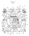
- the rear wall 8 is a frame construction, the four sides 25 to 28th has, which consist of profiled aluminum.
- Three struts 12, 13 and 14 extend to Center 3, in which the drive member 7 of the fan 2 is rotatably mounted.
- Fig. 2 In the shown The embodiment is the drive member 7 a continuously switchable electromagnetic clutch.
- the clutch 7 is equipped with a driven pulley 9 and with on the output side the impeller of the fan 2 connected.
- a carrier 15 is connected to the center 3. At a Not shown embodiment, the carrier 15 is not with the center 3 but with the Frame construction of the rear wall 8 connected.
- the pivot point 16 or pivot point of the clamping lever 17 has been provided on the carrier 15.
- One end 20 of the tensioning lever 17 carries a tensioning roller 18.
- the tensioning roller is 18 connected to a ball bearing 29 at the end 20 of the clamping lever 17.
- the pivot point 16 of the Tensioning lever 17 is of a conventional type.
- a tension spring engages at the other end 21 of tensioning lever 17 23 and a pneumatic cylinder 24 as shown in FIGS. 1, 3 and 4.
- the tension spring 23 and the pneumatic cylinder 24 have a common abutment 32 on the Support strut 12 on.
- the pneumatic cylinder 24 is only attached to the abutment 32 been while a rail 34 has been provided for the function of the tension spring 23, the at its end has a counter bearing 35 for the tension spring 23, which over the operation of the cooling system 1 the tension lever 17 receives forces acting on the tension spring 23.
- the piston rod 33 of the double-acting pneumatic cylinder 24 is extended, whereby the Tension lever 17 rotated about the pivot point 16 and the tension roller 18 assumes a position in which the V-belt 11 can be removed.
- a known clamping element 22 are used, both Functions united. Such a clamping element 22 that a tension spring with a Damping element is z.
- pivotable counter bearing 32 must be provided in order to be able to change the V-belt 11.
- cooler 6 that the cooling system has different coolers 4, 5 and 6.
- the cooler shown is located opposite the cooler 6, so that the cooling system 1 on all four sides has a cooler.
- the cooler 6 and the cooler 5 may be a common coolant cooler.
- the upper cooler 4 a charge air cooler.
- the charge air cooler 4 has a rear edge 30, which is located in the level 31.
- the rear edge 30 of the other coolers 5 and 6 is further in this embodiment in front.
- In front of the level 31 described are the two pulleys 9 and 10 and the tension pulley 18 has been arranged, which in this embodiment is also arranged on a level 19 are.
- the rhyme discs 9 and 10 and the tensioning roller 18 could, however, very well also be offset to each other, that is, not lying in a common plane 19.
- the driving Pulley 10 is provided with a connecting flange 35 to which a not shown Drive shaft of the drive machine is connected. 2 also shows that the Fan drive and the entire cooling system 1 were designed so that no excess after is available at the back, which is why a space-saving, compact design of the cooling system with the Drive machine has been reached.
- a cover 40 is attached, which further into the Interior of the cooling system 1 has leading gradation 41, which is circular in the exemplary embodiment was designed.
Landscapes
- Engineering & Computer Science (AREA)
- Mechanical Engineering (AREA)
- General Engineering & Computer Science (AREA)
- Combustion & Propulsion (AREA)
- Thermal Sciences (AREA)
- Chemical & Material Sciences (AREA)
- Physics & Mathematics (AREA)
- Cooling, Air Intake And Gas Exhaust, And Fuel Tank Arrangements In Propulsion Units (AREA)
- General Details Of Gearings (AREA)
- Devices For Conveying Motion By Means Of Endless Flexible Members (AREA)
- Food-Manufacturing Devices (AREA)
- Cold Air Circulating Systems And Constructional Details In Refrigerators (AREA)
- Power Steering Mechanism (AREA)
Abstract
Description
Claims (8)
- Ventilatorantrieb für die Kühlanlage (1) eines Kraftfahrzeuges, bei der der Ventilator (2) im Zentrum (3) einer kastenförmigen Kühlanlage(1), bestehend aus mehreren Kühlern (4; 5; 6) für unterschiedliche Medien, angeordnet ist, dessen Antriebsorgan (7) in der eingezogenen Rückwand (8) der Kühlanlage (1) gelagert ist und eine angetriebene Riemenscheibe (9) aufweist, die mit einer antreibenden Riemenscheibe (10) der Antriebsmaschine des Kraftfahrzeuges mittels Keilriemen (11) oder dergleichen verbunden ist,
dadurch gekennzeichnet, daß
die Rückwand (8) Tragstreben (12; 13; 14) aufweist, die im Zentrum (3), innerhalb der Kühlanlage (1), zusammenlaufen, wo das Antriebsorgan (7) des Ventilators (2) gelagert ist, wobei außerhalb des Zentrums (3) ein mit der Rückwand (8) verbundener Träger (15) angeordnet ist, an dem sich der Drehpunkt (16) eines Spannhebels (17) befindet, der eine Spannrolle (18) trägt
und daß die antreibende (10), die angetriebene Riemenscheibe (9) und die Spannrolle (18) vor oder in der Ebene (31) angeordnet sind, in der die Hinterkante (30) der Kühler (4; 5; 6) oder die Hinterkante (30) des am weitesten nach hinten überstehenden Kühlers (4) der Kühlanlage (1) liegt. - Ventilatorantrieb nach Anspruch 1, dadurch gekennzeichnet, daß die antreibende (10), die angetriebene Riemenscheibe (9) sowie die Spannrolle (18) in einer gemeinsamen Ebene (19) angeordnet sind.
- Ventilatorantrieb nach Anspruch 1, dadurch gekennzeichnet, daß die Ebene der Spannrolle (18) zu der oder den Ebenen der Riemenscheiben (9; 10) zueinander versetzt angeordnet sind.
- Ventilatorantrieb nach einem der Ansprüche 1 bis 3, dadurch gekennzeichnet, daß die Spannrolle (18) an einem Ende (20) des Spannhebels (17) drehbar gelagert ist, an dessen anderem Ende (21) mindestens ein Spannelement (22) mit einem Ende befestigt ist, dessen anderes Ende an einer der Tragstreben (12) der Rückwand (8) befestigt ist.
- Ventilatorantrieb nach Anspruch 4, dadurch gekennzeichnet, daß zwei Spannelemente (22) vorhanden sind, wovon das eine eine Zugfeder (23) und das andere ein doppelt wirkender pneumatisch beaufschlagbarer Arbeitszylinder (24) ist.
- Ventilatorantrieb nach einem der vorstehenden Ansprüche, dadurch gekennzeichnet, daß zwischen den Tragstreben (12; 13, 14) eine profilierte Abdeckung angeordnet ist.
- Ventilatorantrieb nach einem der vorstehenden Ansprüche, dadurch gekennzeichnet, daß eine der Riemenscheiben (9; 10) mit drehzahlverändernden Mitteln ausgestattet ist und das Antriebsorgan (7) des Ventilators (2) eine Antriebswelle ist.
- Ventilatorantrieb nach einem der Ansprüche 1 bis 6, dadurch gekennzeichnet, daß das Antriebsorgan (7) eine stufenlos schaltbare Kupplung ist, die auf der Antriebsseite mit der Riemenscheibe 9 und auf der Abtriebsseite mit dem Laufrad des Ventilators 2 verbunden ist.
Applications Claiming Priority (2)
| Application Number | Priority Date | Filing Date | Title |
|---|---|---|---|
| DE10018090 | 2000-04-12 | ||
| DE10018090A DE10018090A1 (de) | 2000-04-12 | 2000-04-12 | Ventilatorantrieb |
Publications (3)
| Publication Number | Publication Date |
|---|---|
| EP1146209A2 true EP1146209A2 (de) | 2001-10-17 |
| EP1146209A3 EP1146209A3 (de) | 2003-03-05 |
| EP1146209B1 EP1146209B1 (de) | 2006-09-06 |
Family
ID=7638443
Family Applications (1)
| Application Number | Title | Priority Date | Filing Date |
|---|---|---|---|
| EP01106768A Expired - Lifetime EP1146209B1 (de) | 2000-04-12 | 2001-03-17 | Ventilatorantrieb |
Country Status (4)
| Country | Link |
|---|---|
| US (1) | US6585035B2 (de) |
| EP (1) | EP1146209B1 (de) |
| AT (1) | ATE338883T1 (de) |
| DE (2) | DE10018090A1 (de) |
Cited By (2)
| Publication number | Priority date | Publication date | Assignee | Title |
|---|---|---|---|---|
| CN111854466A (zh) * | 2020-08-03 | 2020-10-30 | 陶天军 | 一种便于装裁和更换冷却液的工程器械散热器结构 |
| CN112676647A (zh) * | 2016-11-03 | 2021-04-20 | 胡斯华纳有限公司 | 发动机驱动的工具 |
Families Citing this family (5)
| Publication number | Priority date | Publication date | Assignee | Title |
|---|---|---|---|---|
| AT6051U1 (de) * | 2002-02-14 | 2003-03-25 | Avl List Gmbh | Kühlsystem für eine brennkraftmaschine |
| US6957735B2 (en) * | 2003-03-11 | 2005-10-25 | Graham Packaging, L.P. | Pneumatic spinner drive tensioning assembly |
| JP2006307690A (ja) * | 2005-04-27 | 2006-11-09 | Kioritz Corp | 動力ユニット |
| US20130167677A1 (en) * | 2012-01-04 | 2013-07-04 | Longyear Tm, Inc. | Over Center Drill Head Gear Shifting System |
| US10563925B2 (en) * | 2017-07-12 | 2020-02-18 | Caterpillar Inc. | Cooling assembly for service vehicle |
Citations (5)
| Publication number | Priority date | Publication date | Assignee | Title |
|---|---|---|---|---|
| EP0020005A1 (de) | 1979-05-24 | 1980-12-10 | P T Components Inc | Riemen-Antriebssysteme mit variabler Geschwindigkeit |
| DE4039815C1 (en) | 1990-12-13 | 1992-05-27 | Mercedes-Benz Aktiengesellschaft, 7000 Stuttgart, De | Tensioner for belt drive with sprung tension roller - has tensioning spring integrated in damping member, with sectional piston rod |
| DE4117336A1 (de) | 1991-05-27 | 1992-12-03 | Behr Gmbh & Co | Luefterantrieb fuer den kuehler eines kraftfahrzeuges |
| WO1998045600A1 (de) | 1997-04-03 | 1998-10-15 | Längerer & Reich Gmbh | Radialventilator |
| DE19950753A1 (de) | 1999-10-21 | 2001-04-26 | Modine Mfg Co | Kühlanlage I |
Family Cites Families (12)
| Publication number | Priority date | Publication date | Assignee | Title |
|---|---|---|---|---|
| US2662748A (en) * | 1952-07-01 | 1953-12-15 | Swingfire Bahamas Ltd | Heat exchanger with adjustable casing for varying recirculation |
| US3921603A (en) * | 1974-03-18 | 1975-11-25 | Caterpillar Tractor Co | Centrifugal fan cooling system |
| US4473362A (en) * | 1981-07-08 | 1984-09-25 | Litens Automotive Inc. | Belt tensioner with variably proportional damping |
| US4694594A (en) * | 1985-09-12 | 1987-09-22 | The Toro Company | Single stage snowthrower |
| DE3912734A1 (de) | 1989-04-19 | 1990-10-25 | Kloeckner Humboldt Deutz Ag | Kuehlsystem |
| US5240461A (en) * | 1992-07-01 | 1993-08-31 | Deere & Company | Blower mounting with belt tensioner |
| US5358452A (en) * | 1993-09-01 | 1994-10-25 | Case Corporation | Belt tensioning mechanism |
| US6478701B1 (en) * | 1997-11-13 | 2002-11-12 | Koyo Seiko Co., Ltd. | Belt type nonstage transmission system |
| US6098385A (en) * | 1998-06-30 | 2000-08-08 | Honda Giken Kogyo Kabushiki Kaisha | Drive control for self-propelled power tool |
| DE19849659A1 (de) * | 1998-10-29 | 2000-05-04 | Schaeffler Waelzlager Ohg | Spanneinrichtung für ein Zugmittel |
| US6216778B1 (en) * | 1998-12-30 | 2001-04-17 | Case Corporation | Cooling system for an off-highway vehicle |
| US6129056A (en) * | 1999-08-23 | 2000-10-10 | Case Corporation | Cooling system for work vehicle |
-
2000
- 2000-04-12 DE DE10018090A patent/DE10018090A1/de not_active Withdrawn
-
2001
- 2001-03-17 EP EP01106768A patent/EP1146209B1/de not_active Expired - Lifetime
- 2001-03-17 DE DE50110913T patent/DE50110913D1/de not_active Expired - Lifetime
- 2001-03-17 AT AT01106768T patent/ATE338883T1/de not_active IP Right Cessation
- 2001-04-12 US US09/833,773 patent/US6585035B2/en not_active Expired - Fee Related
Patent Citations (5)
| Publication number | Priority date | Publication date | Assignee | Title |
|---|---|---|---|---|
| EP0020005A1 (de) | 1979-05-24 | 1980-12-10 | P T Components Inc | Riemen-Antriebssysteme mit variabler Geschwindigkeit |
| DE4039815C1 (en) | 1990-12-13 | 1992-05-27 | Mercedes-Benz Aktiengesellschaft, 7000 Stuttgart, De | Tensioner for belt drive with sprung tension roller - has tensioning spring integrated in damping member, with sectional piston rod |
| DE4117336A1 (de) | 1991-05-27 | 1992-12-03 | Behr Gmbh & Co | Luefterantrieb fuer den kuehler eines kraftfahrzeuges |
| WO1998045600A1 (de) | 1997-04-03 | 1998-10-15 | Längerer & Reich Gmbh | Radialventilator |
| DE19950753A1 (de) | 1999-10-21 | 2001-04-26 | Modine Mfg Co | Kühlanlage I |
Non-Patent Citations (1)
| Title |
|---|
| "drei prinzipien der anordnung und antriebsseitigen verbindung des motors mit dem ventilator der kühlanlage", VTMS-KONFERENZ, May 1999 (1999-05-01) |
Cited By (3)
| Publication number | Priority date | Publication date | Assignee | Title |
|---|---|---|---|---|
| CN112676647A (zh) * | 2016-11-03 | 2021-04-20 | 胡斯华纳有限公司 | 发动机驱动的工具 |
| CN111854466A (zh) * | 2020-08-03 | 2020-10-30 | 陶天军 | 一种便于装裁和更换冷却液的工程器械散热器结构 |
| CN111854466B (zh) * | 2020-08-03 | 2021-04-02 | 青岛永晟热交换器有限公司 | 一种便于装裁和更换冷却液的工程器械散热器结构 |
Also Published As
| Publication number | Publication date |
|---|---|
| US20010035282A1 (en) | 2001-11-01 |
| US6585035B2 (en) | 2003-07-01 |
| DE10018090A1 (de) | 2001-11-29 |
| EP1146209A3 (de) | 2003-03-05 |
| EP1146209B1 (de) | 2006-09-06 |
| DE50110913D1 (de) | 2006-10-19 |
| ATE338883T1 (de) | 2006-09-15 |
Similar Documents
| Publication | Publication Date | Title |
|---|---|---|
| DE60305771T2 (de) | Pump- und Arbeitsfahrzeug | |
| EP0775815B1 (de) | Aggregateträger für Brennkraftmaschine | |
| DE60211273T2 (de) | Integrierter Luftverdichter | |
| DE10048958B4 (de) | Anordnung zum Anbringen von schallabsorbierenden Lamellen eines Arbeitsfahrzeugs | |
| EP0325972A2 (de) | Kühleranordnung, insbesondere für einen Fahrzeugantrieb | |
| EP1146209B1 (de) | Ventilatorantrieb | |
| DE4206121A1 (de) | Antriebsvorrichtung fuer ein oder mehrere durch einen verbrennungsmotor angetriebene zusatzgeraete | |
| DE1108721B (de) | Fuer Schienentriebfahrzeuge mit einer Brennkraftmaschine bestimmte Kuehlanlage | |
| DE10226377B4 (de) | Hilfsantriebssystem in einem Motor | |
| DE4123778C2 (de) | Gleiskettenfahrzeug | |
| DE69510160T2 (de) | Antriebsgerät für eine Fahrkraftmaschine | |
| DE60223643T2 (de) | Horizontales Getriebe- und Schmierölsystem für Teleskopkräne | |
| EP3115242B1 (de) | Lüfterantrieb für ein kraftfahrzeug | |
| DE2659282C2 (de) | ||
| DE3236794C2 (de) | Kühler-Lüfter-System, insbesondere für Omnibusse mit im Heck angeordnetem Fahrzeugmotor | |
| DE19710172A1 (de) | Landwirtschaftliche Erntemaschine | |
| DE19935344A1 (de) | Antriebsvorrichtung zum motorischen Schwenken einer Front- oder Heckklappe eines Kraftfahrzeugs | |
| EP1215157A1 (de) | Anordnung des Aufzugantriebes | |
| DE4039933C2 (de) | ||
| DE19823508C2 (de) | Mobiles Arbeitsfahrzeug mit kompakter Achsbaugruppe | |
| DE102007024504A1 (de) | Lagerung eines Vorderachsgetriebes bei einem Kraftfahrzeug | |
| EP1346867B1 (de) | Angetriebene Zusatzeinrichtung an einem Kraftfahrzeug | |
| DE4221000A1 (de) | Motorische Antriebseinrichtung für ein Torblatt | |
| DE19910047A1 (de) | Hydrostatischer Nabenantrieb | |
| DE69712897T2 (de) | Bus mit klimaanlage |
Legal Events
| Date | Code | Title | Description |
|---|---|---|---|
| PUAI | Public reference made under article 153(3) epc to a published international application that has entered the european phase |
Free format text: ORIGINAL CODE: 0009012 |
|
| AK | Designated contracting states |
Kind code of ref document: A2 Designated state(s): AT BE CH CY DE DK ES FI FR GB GR IE IT LI LU MC NL PT SE TR |
|
| AX | Request for extension of the european patent |
Free format text: AL;LT;LV;MK;RO;SI |
|
| PUAL | Search report despatched |
Free format text: ORIGINAL CODE: 0009013 |
|
| AK | Designated contracting states |
Kind code of ref document: A3 Designated state(s): AT BE CH CY DE DK ES FI FR GB GR IE IT LI LU MC NL PT SE TR |
|
| AX | Request for extension of the european patent |
Extension state: AL LT LV MK RO SI |
|
| RIN1 | Information on inventor provided before grant (corrected) |
Inventor name: VETTER, FRANK Inventor name: ZOBEL, WERNER Inventor name: SOLDNER, JOERG Inventor name: VOSS, MARK G. Inventor name: STRAEHLE, ROLAND Inventor name: EHLERS, MICHAEL Inventor name: WILLMANN, ANDREAS Inventor name: KNECHT, WOLFGANG |
|
| 17P | Request for examination filed |
Effective date: 20030905 |
|
| AKX | Designation fees paid |
Designated state(s): AT BE CH CY DE DK ES FI FR GB GR IE IT LI LU MC NL PT SE TR |
|
| GRAP | Despatch of communication of intention to grant a patent |
Free format text: ORIGINAL CODE: EPIDOSNIGR1 |
|
| GRAS | Grant fee paid |
Free format text: ORIGINAL CODE: EPIDOSNIGR3 |
|
| GRAA | (expected) grant |
Free format text: ORIGINAL CODE: 0009210 |
|
| AK | Designated contracting states |
Kind code of ref document: B1 Designated state(s): AT BE CH CY DE DK ES FI FR GB GR IE IT LI LU MC NL PT SE TR |
|
| PG25 | Lapsed in a contracting state [announced via postgrant information from national office to epo] |
Ref country code: IT Free format text: LAPSE BECAUSE OF FAILURE TO SUBMIT A TRANSLATION OF THE DESCRIPTION OR TO PAY THE FEE WITHIN THE PRESCRIBED TIME-LIMIT;WARNING: LAPSES OF ITALIAN PATENTS WITH EFFECTIVE DATE BEFORE 2007 MAY HAVE OCCURRED AT ANY TIME BEFORE 2007. THE CORRECT EFFECTIVE DATE MAY BE DIFFERENT FROM THE ONE RECORDED. Effective date: 20060906 Ref country code: FI Free format text: LAPSE BECAUSE OF FAILURE TO SUBMIT A TRANSLATION OF THE DESCRIPTION OR TO PAY THE FEE WITHIN THE PRESCRIBED TIME-LIMIT Effective date: 20060906 Ref country code: IE Free format text: LAPSE BECAUSE OF FAILURE TO SUBMIT A TRANSLATION OF THE DESCRIPTION OR TO PAY THE FEE WITHIN THE PRESCRIBED TIME-LIMIT Effective date: 20060906 Ref country code: NL Free format text: LAPSE BECAUSE OF FAILURE TO SUBMIT A TRANSLATION OF THE DESCRIPTION OR TO PAY THE FEE WITHIN THE PRESCRIBED TIME-LIMIT Effective date: 20060906 |
|
| REG | Reference to a national code |
Ref country code: GB Ref legal event code: FG4D Free format text: NOT ENGLISH |
|
| REG | Reference to a national code |
Ref country code: CH Ref legal event code: EP |
|
| REG | Reference to a national code |
Ref country code: IE Ref legal event code: FG4D Free format text: LANGUAGE OF EP DOCUMENT: GERMAN |
|
| REF | Corresponds to: |
Ref document number: 50110913 Country of ref document: DE Date of ref document: 20061019 Kind code of ref document: P |
|
| PG25 | Lapsed in a contracting state [announced via postgrant information from national office to epo] |
Ref country code: SE Free format text: LAPSE BECAUSE OF FAILURE TO SUBMIT A TRANSLATION OF THE DESCRIPTION OR TO PAY THE FEE WITHIN THE PRESCRIBED TIME-LIMIT Effective date: 20061206 Ref country code: DK Free format text: LAPSE BECAUSE OF FAILURE TO SUBMIT A TRANSLATION OF THE DESCRIPTION OR TO PAY THE FEE WITHIN THE PRESCRIBED TIME-LIMIT Effective date: 20061206 |
|
| PG25 | Lapsed in a contracting state [announced via postgrant information from national office to epo] |
Ref country code: ES Free format text: LAPSE BECAUSE OF FAILURE TO SUBMIT A TRANSLATION OF THE DESCRIPTION OR TO PAY THE FEE WITHIN THE PRESCRIBED TIME-LIMIT Effective date: 20061217 |
|
| GBT | Gb: translation of ep patent filed (gb section 77(6)(a)/1977) |
Effective date: 20061214 |
|
| NLV1 | Nl: lapsed or annulled due to failure to fulfill the requirements of art. 29p and 29m of the patents act | ||
| ET | Fr: translation filed | ||
| REG | Reference to a national code |
Ref country code: IE Ref legal event code: FD4D |
|
| PLBE | No opposition filed within time limit |
Free format text: ORIGINAL CODE: 0009261 |
|
| STAA | Information on the status of an ep patent application or granted ep patent |
Free format text: STATUS: NO OPPOSITION FILED WITHIN TIME LIMIT |
|
| 26N | No opposition filed |
Effective date: 20070607 |
|
| REG | Reference to a national code |
Ref country code: CH Ref legal event code: PL |
|
| BERE | Be: lapsed |
Owner name: MODINE MANUFACTURING CY Effective date: 20070331 |
|
| PG25 | Lapsed in a contracting state [announced via postgrant information from national office to epo] |
Ref country code: BE Free format text: LAPSE BECAUSE OF NON-PAYMENT OF DUE FEES Effective date: 20070331 |
|
| PG25 | Lapsed in a contracting state [announced via postgrant information from national office to epo] |
Ref country code: MC Free format text: LAPSE BECAUSE OF NON-PAYMENT OF DUE FEES Effective date: 20070331 |
|
| PG25 | Lapsed in a contracting state [announced via postgrant information from national office to epo] |
Ref country code: LI Free format text: LAPSE BECAUSE OF NON-PAYMENT OF DUE FEES Effective date: 20070331 Ref country code: CH Free format text: LAPSE BECAUSE OF NON-PAYMENT OF DUE FEES Effective date: 20070331 |
|
| PG25 | Lapsed in a contracting state [announced via postgrant information from national office to epo] |
Ref country code: GR Free format text: LAPSE BECAUSE OF FAILURE TO SUBMIT A TRANSLATION OF THE DESCRIPTION OR TO PAY THE FEE WITHIN THE PRESCRIBED TIME-LIMIT Effective date: 20061207 |
|
| PG25 | Lapsed in a contracting state [announced via postgrant information from national office to epo] |
Ref country code: AT Free format text: LAPSE BECAUSE OF NON-PAYMENT OF DUE FEES Effective date: 20070317 |
|
| PG25 | Lapsed in a contracting state [announced via postgrant information from national office to epo] |
Ref country code: CY Free format text: LAPSE BECAUSE OF FAILURE TO SUBMIT A TRANSLATION OF THE DESCRIPTION OR TO PAY THE FEE WITHIN THE PRESCRIBED TIME-LIMIT Effective date: 20060906 Ref country code: LU Free format text: LAPSE BECAUSE OF NON-PAYMENT OF DUE FEES Effective date: 20070317 |
|
| PG25 | Lapsed in a contracting state [announced via postgrant information from national office to epo] |
Ref country code: TR Free format text: LAPSE BECAUSE OF FAILURE TO SUBMIT A TRANSLATION OF THE DESCRIPTION OR TO PAY THE FEE WITHIN THE PRESCRIBED TIME-LIMIT Effective date: 20060906 |
|
| PG25 | Lapsed in a contracting state [announced via postgrant information from national office to epo] |
Ref country code: PT Free format text: LAPSE BECAUSE OF FAILURE TO SUBMIT A TRANSLATION OF THE DESCRIPTION OR TO PAY THE FEE WITHIN THE PRESCRIBED TIME-LIMIT Effective date: 20060906 |
|
| PGFP | Annual fee paid to national office [announced via postgrant information from national office to epo] |
Ref country code: DE Payment date: 20140331 Year of fee payment: 14 |
|
| PGFP | Annual fee paid to national office [announced via postgrant information from national office to epo] |
Ref country code: GB Payment date: 20140320 Year of fee payment: 14 |
|
| PGFP | Annual fee paid to national office [announced via postgrant information from national office to epo] |
Ref country code: FR Payment date: 20140410 Year of fee payment: 14 |
|
| REG | Reference to a national code |
Ref country code: DE Ref legal event code: R119 Ref document number: 50110913 Country of ref document: DE |
|
| GBPC | Gb: european patent ceased through non-payment of renewal fee |
Effective date: 20150317 |
|
| REG | Reference to a national code |
Ref country code: FR Ref legal event code: ST Effective date: 20151130 |
|
| PG25 | Lapsed in a contracting state [announced via postgrant information from national office to epo] |
Ref country code: GB Free format text: LAPSE BECAUSE OF NON-PAYMENT OF DUE FEES Effective date: 20150317 Ref country code: DE Free format text: LAPSE BECAUSE OF NON-PAYMENT OF DUE FEES Effective date: 20151001 |
|
| PG25 | Lapsed in a contracting state [announced via postgrant information from national office to epo] |
Ref country code: FR Free format text: LAPSE BECAUSE OF NON-PAYMENT OF DUE FEES Effective date: 20150331 |