EP1146204A2 - Joint abradable - Google Patents
Joint abradable Download PDFInfo
- Publication number
- EP1146204A2 EP1146204A2 EP01302627A EP01302627A EP1146204A2 EP 1146204 A2 EP1146204 A2 EP 1146204A2 EP 01302627 A EP01302627 A EP 01302627A EP 01302627 A EP01302627 A EP 01302627A EP 1146204 A2 EP1146204 A2 EP 1146204A2
- Authority
- EP
- European Patent Office
- Prior art keywords
- sealing element
- walls
- radially inner
- radially
- gas turbine
- Prior art date
- Legal status (The legal status is an assumption and is not a legal conclusion. Google has not performed a legal analysis and makes no representation as to the accuracy of the status listed.)
- Withdrawn
Links
Images
Classifications
-
- B—PERFORMING OPERATIONS; TRANSPORTING
- B23—MACHINE TOOLS; METAL-WORKING NOT OTHERWISE PROVIDED FOR
- B23H—WORKING OF METAL BY THE ACTION OF A HIGH CONCENTRATION OF ELECTRIC CURRENT ON A WORKPIECE USING AN ELECTRODE WHICH TAKES THE PLACE OF A TOOL; SUCH WORKING COMBINED WITH OTHER FORMS OF WORKING OF METAL
- B23H9/00—Machining specially adapted for treating particular metal objects or for obtaining special effects or results on metal objects
- B23H9/10—Working turbine blades or nozzles
-
- F—MECHANICAL ENGINEERING; LIGHTING; HEATING; WEAPONS; BLASTING
- F01—MACHINES OR ENGINES IN GENERAL; ENGINE PLANTS IN GENERAL; STEAM ENGINES
- F01D—NON-POSITIVE DISPLACEMENT MACHINES OR ENGINES, e.g. STEAM TURBINES
- F01D11/00—Preventing or minimising internal leakage of working-fluid, e.g. between stages
- F01D11/08—Preventing or minimising internal leakage of working-fluid, e.g. between stages for sealing space between rotor blade tips and stator
- F01D11/12—Preventing or minimising internal leakage of working-fluid, e.g. between stages for sealing space between rotor blade tips and stator using a rubstrip, e.g. erodible. deformable or resiliently-biased part
-
- F—MECHANICAL ENGINEERING; LIGHTING; HEATING; WEAPONS; BLASTING
- F16—ENGINEERING ELEMENTS AND UNITS; GENERAL MEASURES FOR PRODUCING AND MAINTAINING EFFECTIVE FUNCTIONING OF MACHINES OR INSTALLATIONS; THERMAL INSULATION IN GENERAL
- F16J—PISTONS; CYLINDERS; SEALINGS
- F16J15/00—Sealings
- F16J15/44—Free-space packings
- F16J15/445—Free-space packings with means for adjusting the clearance
-
- Y—GENERAL TAGGING OF NEW TECHNOLOGICAL DEVELOPMENTS; GENERAL TAGGING OF CROSS-SECTIONAL TECHNOLOGIES SPANNING OVER SEVERAL SECTIONS OF THE IPC; TECHNICAL SUBJECTS COVERED BY FORMER USPC CROSS-REFERENCE ART COLLECTIONS [XRACs] AND DIGESTS
- Y10—TECHNICAL SUBJECTS COVERED BY FORMER USPC
- Y10T—TECHNICAL SUBJECTS COVERED BY FORMER US CLASSIFICATION
- Y10T29/00—Metal working
- Y10T29/49—Method of mechanical manufacture
- Y10T29/49229—Prime mover or fluid pump making
- Y10T29/49297—Seal or packing making
Definitions
- the invention relates to an abradable seal for a gas turbine engine.
- a sealing structure which may comprise an annular seal or a seal segment ring made up of a plurality of arc shaped seal segments. Because the turbine blades expand and contract as their temperatures vary in use and centrifugal loads are imposed upon them, it is normal to provide a small gap between the turbine blade tips and the seal, to allow for this fluctuation.
- abradable seals for sealing between the turbine blade tips and the sealing structure. This enables the tips of the turbine blades to wear away the seal to an optimum size and shape without causing damage to the turbine blade tips.
- abradable seals may consist of an open cell foil honeycomb which is brazed in place and subsequently filled with a suitable abradable material, such as a metallic powder.
- the foil honeycomb acts as a support for the abradable material and the abradable material and the supporting foil honeycomb is subsequently partially worn away by the rotating turbine blades, thus forming a seal.
- the seals may suffer from progressive oxidation attack if the foil material has inadequate oxidation resistance.
- problems may be experienced with the brazed joints, and the seals may be difficult to cool.
- a sealing element for positioning radially outwardly of at least some of the aerofoil blades of a gas turbine engine, a radially inner surface region of the sealing element including an integrally formed seal structure comprising a plurality of inwardly projecting walls.
- the sealing element may comprise or form part of a generally annular housing for surrounding the tips of the blades of the turbine of said engine.
- the sealing element may comprise a seal segment.
- the walls project substantially radially inwardly.
- radially inner edges of the walls define a substantially arc shaped inner face of the sealing element.
- the seal structure is provided over substantially the whole of a radially inner surface region of the sealing element.
- the thickness of the walls may reduce generally towards their radially inner edges.
- the walls may be shaped to form a plurality of radially open cells and each cell may be open only at a radially inner side.
- One or more of the cells may be substantially diamond shaped when viewed in the radial direction.
- the cells may be all substantially the same size or may be different sizes.
- the thickness of the walls may increase at their radially inner edges, such that the size of the cells reduces at their open radially inner sides.
- a sealing element as defined in any of the preceding four paragraphs, wherein openings between the walls are at least partially filled with an abradable sealing material.
- the abradable sealing material may protrude radially inwardly beyond radially inner edges of the walls.
- the walls may be abradable.
- abradable it is meant that the material may be worn away by contact with the tips of rotating aerofoil blades, without causing significant damage to the blade tips.
- seal segment ring for a turbine of a gas turbine engine, the seal segment ring including a plurality of sealing elements as defined in any of the preceding nine paragraphs.
- a gas turbine engine including a turbine comprising a seal segment ring as defined in the preceding paragraph.
- the turbine may be the high pressure turbine of the gas turbine engine.
- a sealing element for positioning radially outwardly of at least some of the aerofoil blades of a gas turbine engine, the method including the step of integrally forming in a radially inner surface region of the seal segment a seal structure comprising a plurality of radially inwardly projecting walls.
- the projecting walls may be formed by electro-discharge machining.
- the method may include the step of machining the walls using an electrode having a generally complementary shape to at least a part of the seal structure.
- the method may include the step of manufacturing the electrode by machining the electrode to a generally desired radial profile and subsequently wire cutting grooves into the electrode, the grooves being for subsequently forming the walls of the seal structure.
- the method may include the step of integrally casting the walls into the sealing element.
- the method includes the further step of electro-chemically machining or etching the seal structure to reduce the thickness of the cast walls.
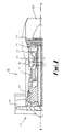
- a ducted fan gas turbine engine generally indicated at 10 comprises, in axial flow series, an air intake 12, a propulsive fan 14, an intermediate pressure compressor 16, a high pressure compressor 18, combustion equipment 20, a high pressure turbine 22, an intermediate pressure turbine 24, a low pressure turbine 26 and an exhaust nozzle 28.
- the gas turbine engine 10 works in the conventional manner so that air entering the intake 12 is accelerated by the fan 14 to produce two air flows, a first air flow into the intermediate pressure compressor 16 and a second airflow which provides propulsive thrust.
- the intermediate pressure compressor 16 compresses the air flow directed into it before delivering the air to the high pressure compressor 18 where further compression takes place.
- the compressed air exhausted from the high pressure compressor 18 is directed into the combustion equipment 20 where it is mixed with fuel and the mixture combusted.
- the resultant hot combustion products then expand through and thereby drive the high, intermediate and low pressure turbines 22, 24 and 26 before being exhausted through the nozzle 28 to provide additional propulsive thrust.
- the high, intermediate and low pressure turbines 22, 24 and 26 respectively drive the high and intermediate pressure compressors 16 and 18 and the fan 14 by suitable interconnecting shafts.
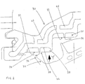
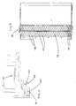
- Figs. 2 to 4 illustrates a turbine seal segment 30 for the high pressure turbine 22.
- a plurality of arc shaped sealing elements in the form of a turbine seal segment together form a substantially cylindrical seal segment ring which encases the rotating high pressure turbine blades 32 (see Fig. 2).
- a small gap 34 is provided between the tips 36 of the turbine blades 32 and a radially inner surface 33 of the seal segment 30. The size of the gap 34 varies with time for various reasons, including variations in the temperatures of the turbine blades 32 and other components.
- an open cell structure 38 is formed integrally with the turbine seal segment 30 in the region of its radially inner surface 33.
- the open cell structure 38 includes upstanding walls 40 which project radially inwardly.
- the walls 40 define therebetween a plurality of open cells 44, the cells 44 having generally circumferential bases 42.
- the cells 44 are able to receive and support an abradable material such as a metallic powder.
- the cells 44 are generally diamond shaped when viewed in the radial direction of the turbine and the walls are oriented at about 30° to the axial direction of the turbine, in use.
- a first set of generally parallel walls crosses over and intersects a second set of generally parallel walls to form the diamond shaped cells 44.
- the walls 40 may project about 1mm to 3mm radially inwardly of the surface 42.
- the width of the walls 40 is about 0.2mm to 0.3mm and the generally parallel walls are located about 2mm to 2.5mm apart.
- the walls are generally rectangular in section.
- Cooling channels 45 are provided within the seal segment 30, radially outwardly of the cell structure 38. Air flowing through the cooling channels helps to cool the cell structure 38 and any abradable material located therein.
- the open cell structure 38 may be formed by electro-discharge machining, using an electrode having a generally complementary shape to the structure to be formed on the turbine seal segment.
- the electrode may be manufactured by machining to the required radial profile and subsequently wire cutting to produce a series of grooves in the pattern of the walls required in the open cell structure.
- the electrode may then be used to machine the open cells 44 in the seal segment 30, the grooves formed by wire cutting the electrode producing the upstanding walls 40 of the open cell structure 38. Radially inner edges of the walls may subsequently be machined to a desired profile.
- the surfaces of the cells 44 may be nickel plated, and the cells may subsequently be filled with the abradable material. In use the blade tips of the high pressure turbine blades wear away the abradable material and the walls 40. Alternatively, the cells may be overfilled, such that the abradable material projects radially inwardly beyond the radially inner edges of the walls 40.
- the open cell structure 38 acts as a retention system for the abradable material, thus minimising damage to the walls 40 and facilitating repair of the structure.
- the abradable material may include a metallic powder, which may be hardened and sintered. Alternatively materials such as ceramic powders might be used.
- the above described embodiment thus provides a turbine seal segment which overcomes many of the problems associated with the prior art.
- the depth of the abradable material may be reduced since extra depth to accommodate wicked braze material is not required.
- the walls of the open cell structure have a relatively high oxidation resistance and are easily cooled because they are positioned near to the cooling channels 45.
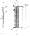
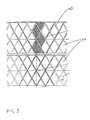
- Fig. 6 and 7 illustrate an alternative embodiment of the invention, in which corresponding reference numerals are used for equivalent parts.
- the open cell structure 38 includes upstanding walls 40 which define therebetween a plurality of cells.
- a small number of generally diamond shaped cells 44 are located at the outer edges of the seal segment.
- the majority of the cells 144 form elongate rhomboid shapes when viewed in the radial direction of the turbine.
- the section of the walls illustrated is generally rectangular. However, an "Eiffel tower" section may be used, to improve cooling. In this embodiment, the width of the walls is increased towards their bases, thus providing improved transfer of heat to the cooling channels 45.
- the width of the walls may however be somewhat increased at their radially inner edges, forming a reentrant shape, thus helping to prevent abradable material from becoming detached from the cell structure.
- the open cells need not be diamond or rhomboid shaped, but for example be rectangular, triangular, etc.
- the cells may be discrete as illustrated, or may interconnect with one another.
- a plurality of closely spaced walls or rails, which may be parallel, may form a seal structure.
- the seal structure may act as a retention matrix for abradable material as described above, or may itself form the seal, with no additional sealing material being used.
- the seal structure need not be formed by electro-discharge machining. Instead, for example, the structure may be cast integrally into the seal segment.
- electro-chemical machining or etching may be used to reduce the thickness of the walls in the sealing structure.
Applications Claiming Priority (2)
| Application Number | Priority Date | Filing Date | Title |
|---|---|---|---|
| GBGB0008892.2A GB0008892D0 (en) | 2000-04-12 | 2000-04-12 | Abradable seals |
| GB0008892 | 2000-04-12 |
Publications (2)
| Publication Number | Publication Date |
|---|---|
| EP1146204A2 true EP1146204A2 (fr) | 2001-10-17 |
| EP1146204A3 EP1146204A3 (fr) | 2003-07-23 |
Family
ID=9889678
Family Applications (1)
| Application Number | Title | Priority Date | Filing Date |
|---|---|---|---|
| EP01302627A Withdrawn EP1146204A3 (fr) | 2000-04-12 | 2001-03-21 | Joint abradable |
Country Status (3)
| Country | Link |
|---|---|
| US (1) | US6644914B2 (fr) |
| EP (1) | EP1146204A3 (fr) |
| GB (1) | GB0008892D0 (fr) |
Cited By (10)
| Publication number | Priority date | Publication date | Assignee | Title |
|---|---|---|---|---|
| EP1452696A2 (fr) * | 2003-02-27 | 2004-09-01 | ROLLS-ROYCE plc | Joint abradable |
| US7029232B2 (en) | 2003-02-27 | 2006-04-18 | Rolls-Royce Plc | Abradable seals |
| WO2008103163A2 (fr) * | 2007-02-22 | 2008-08-28 | Siemens Energy, Inc. | Composite de matrice de céramique abradable par une réduction d'une zone de surface |
| EP2174740A1 (fr) * | 2008-10-08 | 2010-04-14 | Siemens Aktiengesellschaft | Joint en nids d'abeille et son procédé de production |
| EP2410133A1 (fr) * | 2010-07-22 | 2012-01-25 | Siemens Aktiengesellschaft | Turbine à gaz et procédé d'étanchéification de courants de fuites |
| EP2602043A1 (fr) * | 2011-12-06 | 2013-06-12 | General Electric Company | Joint de nid d'abeilles pour aile d'ange abradable |
| EP2821172A1 (fr) * | 2013-07-02 | 2015-01-07 | Carl Freudenberg KG | Procédé de fabrication de microstructures dans des éléments d'étanchéité |
| EP2450130A3 (fr) * | 2010-11-05 | 2016-01-20 | United Technologies Corporation | Moulage d'un composant doté d'un joint intégral |
| RU2608664C2 (ru) * | 2011-12-20 | 2017-01-23 | Нуово Пиньоне С.п.А. | Сотовый сальник и способ его изготовления |
| US9903217B2 (en) | 2014-10-01 | 2018-02-27 | Rolls-Royce Plc | Sealing element |
Families Citing this family (15)
| Publication number | Priority date | Publication date | Assignee | Title |
|---|---|---|---|---|
| GB0029337D0 (en) * | 2000-12-01 | 2001-01-17 | Rolls Royce Plc | A seal segment for a turbine |
| DE102006004090A1 (de) * | 2006-01-28 | 2007-08-02 | Mtu Aero Engines Gmbh | Leitschaufelsegment einer Gasturbine |
| US20080080972A1 (en) * | 2006-09-29 | 2008-04-03 | General Electric Company | Stationary-rotating assemblies having surface features for enhanced containment of fluid flow, and related processes |
| US7871244B2 (en) * | 2007-02-15 | 2011-01-18 | Siemens Energy, Inc. | Ring seal for a turbine engine |
| US8167547B2 (en) * | 2007-03-05 | 2012-05-01 | United Technologies Corporation | Gas turbine engine with canted pocket and canted knife edge seal |
| US20080260523A1 (en) * | 2007-04-18 | 2008-10-23 | Ioannis Alvanos | Gas turbine engine with integrated abradable seal |
| US20080260522A1 (en) * | 2007-04-18 | 2008-10-23 | Ioannis Alvanos | Gas turbine engine with integrated abradable seal and mount plate |
| US7967559B2 (en) * | 2007-05-30 | 2011-06-28 | General Electric Company | Stator-rotor assembly having surface feature for enhanced containment of gas flow and related processes |
| JPWO2014077058A1 (ja) * | 2012-11-13 | 2017-01-05 | 三菱重工コンプレッサ株式会社 | 回転機械 |
| GB201311460D0 (en) * | 2013-06-27 | 2013-08-14 | Rolls Royce Plc | An abradable liner for a gas turbine engine |
| EP3111049A1 (fr) * | 2014-02-25 | 2017-01-04 | Siemens Aktiengesellschaft | Couche abradable de turbine présentant des motifs d'élément de surface pixellisés de direction d'écoulement d'air |
| JP6209199B2 (ja) * | 2015-12-09 | 2017-10-04 | 三菱日立パワーシステムズ株式会社 | シールフィン,シール構造,ターボ機械及びシールフィンの製造方法 |
| US10408077B2 (en) * | 2017-01-26 | 2019-09-10 | United Tehnologies Corporation | Gas turbine seal |
| US10774670B2 (en) | 2017-06-07 | 2020-09-15 | General Electric Company | Filled abradable seal component and associated methods thereof |
| US20190218925A1 (en) * | 2018-01-18 | 2019-07-18 | General Electric Company | Turbine engine shroud |
Citations (1)
| Publication number | Priority date | Publication date | Assignee | Title |
|---|---|---|---|---|
| JPH08232703A (ja) | 1995-02-23 | 1996-09-10 | Toyota Motor Corp | 燃料圧力制御装置 |
Family Cites Families (9)
| Publication number | Priority date | Publication date | Assignee | Title |
|---|---|---|---|---|
| US3042365A (en) * | 1957-11-08 | 1962-07-03 | Gen Motors Corp | Blade shrouding |
| GB851323A (en) | 1957-11-08 | 1960-10-12 | Gen Motors Corp | Axial-flow compressors and turbines |
| CA963497A (en) | 1970-12-21 | 1975-02-25 | Gould Inc. | Powder metal honeycomb |
| GB2017228B (en) | 1977-07-14 | 1982-05-06 | Pratt & Witney Aircraft Of Can | Shroud for a turbine rotor |
| GB2146707B (en) | 1983-09-14 | 1987-08-05 | Rolls Royce | Turbine |
| DE3413534A1 (de) * | 1984-04-10 | 1985-10-24 | MTU Motoren- und Turbinen-Union München GmbH, 8000 München | Gehaeuse einer stroemungsmaschine |
| US4764089A (en) * | 1986-08-07 | 1988-08-16 | Allied-Signal Inc. | Abradable strain-tolerant ceramic coated turbine shroud |
| US4884820A (en) | 1987-05-19 | 1989-12-05 | Union Carbide Corporation | Wear resistant, abrasive laser-engraved ceramic or metallic carbide surfaces for rotary labyrinth seal members |
| US5951892A (en) * | 1996-12-10 | 1999-09-14 | Chromalloy Gas Turbine Corporation | Method of making an abradable seal by laser cutting |
-
2000
- 2000-04-12 GB GBGB0008892.2A patent/GB0008892D0/en not_active Ceased
-
2001
- 2001-03-21 EP EP01302627A patent/EP1146204A3/fr not_active Withdrawn
- 2001-03-23 US US09/815,041 patent/US6644914B2/en not_active Expired - Lifetime
Patent Citations (1)
| Publication number | Priority date | Publication date | Assignee | Title |
|---|---|---|---|---|
| JPH08232703A (ja) | 1995-02-23 | 1996-09-10 | Toyota Motor Corp | 燃料圧力制御装置 |
Cited By (19)
| Publication number | Priority date | Publication date | Assignee | Title |
|---|---|---|---|---|
| EP1452696A2 (fr) * | 2003-02-27 | 2004-09-01 | ROLLS-ROYCE plc | Joint abradable |
| GB2398844A (en) * | 2003-02-27 | 2004-09-01 | Rolls Royce Plc | Abradable seals for gas turbine engines |
| GB2398844B (en) * | 2003-02-27 | 2005-04-13 | Rolls Royce Plc | Abradable seals |
| US7029232B2 (en) | 2003-02-27 | 2006-04-18 | Rolls-Royce Plc | Abradable seals |
| EP1452696A3 (fr) * | 2003-02-27 | 2006-10-04 | ROLLS-ROYCE plc | Joint abradable |
| WO2008103163A2 (fr) * | 2007-02-22 | 2008-08-28 | Siemens Energy, Inc. | Composite de matrice de céramique abradable par une réduction d'une zone de surface |
| WO2008103163A3 (fr) * | 2007-02-22 | 2009-05-22 | Siemens Energy Inc | Composite de matrice de céramique abradable par une réduction d'une zone de surface |
| JP2010519161A (ja) * | 2007-02-22 | 2010-06-03 | シーメンス エナジー インコーポレイテッド | 表面積の縮小により磨耗可能なセラミックマトリックス複合材料 |
| WO2010040599A1 (fr) * | 2008-10-08 | 2010-04-15 | Siemens Aktiengesellschaft | Joint en nid-d’abeilles et son procédé de production |
| EP2174740A1 (fr) * | 2008-10-08 | 2010-04-14 | Siemens Aktiengesellschaft | Joint en nids d'abeille et son procédé de production |
| CN102176995A (zh) * | 2008-10-08 | 2011-09-07 | 西门子公司 | 蜂窝密封及生产该蜂窝密封的方法 |
| RU2515869C2 (ru) * | 2008-10-08 | 2014-05-20 | Сименс Акциенгезелльшафт | Сотовое уплотнение и способ его изготовления |
| EP2410133A1 (fr) * | 2010-07-22 | 2012-01-25 | Siemens Aktiengesellschaft | Turbine à gaz et procédé d'étanchéification de courants de fuites |
| EP2450130A3 (fr) * | 2010-11-05 | 2016-01-20 | United Technologies Corporation | Moulage d'un composant doté d'un joint intégral |
| EP2602043A1 (fr) * | 2011-12-06 | 2013-06-12 | General Electric Company | Joint de nid d'abeilles pour aile d'ange abradable |
| CN103143796A (zh) * | 2011-12-06 | 2013-06-12 | 通用电气公司 | 用于可磨损天使翼的蜂窝结构 |
| RU2608664C2 (ru) * | 2011-12-20 | 2017-01-23 | Нуово Пиньоне С.п.А. | Сотовый сальник и способ его изготовления |
| EP2821172A1 (fr) * | 2013-07-02 | 2015-01-07 | Carl Freudenberg KG | Procédé de fabrication de microstructures dans des éléments d'étanchéité |
| US9903217B2 (en) | 2014-10-01 | 2018-02-27 | Rolls-Royce Plc | Sealing element |
Also Published As
| Publication number | Publication date |
|---|---|
| US20010031201A1 (en) | 2001-10-18 |
| GB0008892D0 (en) | 2000-05-31 |
| US6644914B2 (en) | 2003-11-11 |
| EP1146204A3 (fr) | 2003-07-23 |
Similar Documents
| Publication | Publication Date | Title |
|---|---|---|
| US6644914B2 (en) | Abradable seals | |
| EP1985808B1 (fr) | Un procédé de fabrication d'un joint abradable | |
| EP1985807B1 (fr) | Garniture d'étanchéité de turbine à gaz et procédé associé de fabrication | |
| KR100574345B1 (ko) | 세그먼트가 형성된 스퀼러 팁을 구비한 터빈 블레이드 | |
| EP2636853B1 (fr) | Ensemble d'étanchéité destiné à être utilisé dans une machine rotative et procédés d'assemblage d'une machine rotative | |
| CN102128059B (zh) | 涡轮喷嘴组件 | |
| US7029232B2 (en) | Abradable seals | |
| US5096376A (en) | Low windage corrugated seal facing strip | |
| US8162598B2 (en) | Gas turbine sealing apparatus | |
| JP5503662B2 (ja) | 鋸壁形タービンノズル | |
| US20120034101A1 (en) | Turbine blade squealer tip | |
| US20090014964A1 (en) | Angled honeycomb seal between turbine rotors and turbine stators in a turbine engine | |
| EP3002417B1 (fr) | Élément de joint | |
| US6887039B2 (en) | Stationary blade in gas turbine and gas turbine comprising the same | |
| EP1132576B1 (fr) | Virole de turbine comprenant un dispositif pour minimiser les gradients thermiques et procédé d'assemblage d'un moteur à turbine a gaz comportant une telle virole | |
| US20200003060A1 (en) | Turbine element for high pressure drop and heat transfer | |
| US10822976B2 (en) | Nozzle insert rib cap | |
| EP1452696B1 (fr) | Procéde de fabrication d'un élément d'étanchéité | |
| CN114585802B (zh) | 涡轮叶片、制造涡轮叶片的方法和整修涡轮叶片的方法 | |
| EP3351739B1 (fr) | Élément d'étanchéité et son procédé de fabrication | |
| EP3543468A1 (fr) | Ensemble de carénage d'extrémité de turbine avec plusieurs segments de carénage dotés d'un agencement d'étanchéité inter-segments | |
| JP2016200143A (ja) | シールピンを有するガスタービンバケットシャンク | |
| US10731494B2 (en) | Overhanging seal assembly for a gas turbine | |
| GB2382380A (en) | A removable abradable lining for the casing assembly of a gas turbine engine | |
| US10648354B2 (en) | Turbine wheels, turbine engines including the same, and methods of forming turbine wheels with improved seal plate sealing |
Legal Events
| Date | Code | Title | Description |
|---|---|---|---|
| PUAI | Public reference made under article 153(3) epc to a published international application that has entered the european phase |
Free format text: ORIGINAL CODE: 0009012 |
|
| AK | Designated contracting states |
Kind code of ref document: A2 Designated state(s): AT BE CH CY DE DK ES FI FR GB GR IE IT LI LU MC NL PT SE TR |
|
| AX | Request for extension of the european patent |
Free format text: AL;LT;LV;MK;RO;SI |
|
| PUAL | Search report despatched |
Free format text: ORIGINAL CODE: 0009013 |
|
| AK | Designated contracting states |
Designated state(s): AT BE CH CY DE DK ES FI FR GB GR IE IT LI LU MC NL PT SE TR |
|
| AX | Request for extension of the european patent |
Extension state: AL LT LV MK RO SI |
|
| 17P | Request for examination filed |
Effective date: 20030626 |
|
| AKX | Designation fees paid |
Designated state(s): DE FR GB |
|
| 17Q | First examination report despatched |
Effective date: 20070806 |
|
| STAA | Information on the status of an ep patent application or granted ep patent |
Free format text: STATUS: THE APPLICATION IS DEEMED TO BE WITHDRAWN |
|
| 18D | Application deemed to be withdrawn |
Effective date: 20071218 |