EP1452696B1 - Procéde de fabrication d'un élément d'étanchéité - Google Patents
Procéde de fabrication d'un élément d'étanchéité Download PDFInfo
- Publication number
- EP1452696B1 EP1452696B1 EP20030258005 EP03258005A EP1452696B1 EP 1452696 B1 EP1452696 B1 EP 1452696B1 EP 20030258005 EP20030258005 EP 20030258005 EP 03258005 A EP03258005 A EP 03258005A EP 1452696 B1 EP1452696 B1 EP 1452696B1
- Authority
- EP
- European Patent Office
- Prior art keywords
- walls
- radially inner
- projecting walls
- sealing element
- inwardly
- Prior art date
- Legal status (The legal status is an assumption and is not a legal conclusion. Google has not performed a legal analysis and makes no representation as to the accuracy of the status listed.)
- Expired - Lifetime
Links
- 238000007789 sealing Methods 0.000 title claims description 27
- 238000004519 manufacturing process Methods 0.000 title claims description 7
- 238000000034 method Methods 0.000 claims description 25
- 239000000843 powder Substances 0.000 claims description 21
- 229910003460 diamond Inorganic materials 0.000 claims description 8
- 239000010432 diamond Substances 0.000 claims description 8
- 230000008021 deposition Effects 0.000 claims description 5
- 230000007423 decrease Effects 0.000 claims 1
- 210000004027 cell Anatomy 0.000 description 49
- 239000000463 material Substances 0.000 description 33
- 239000000758 substrate Substances 0.000 description 15
- 239000007789 gas Substances 0.000 description 13
- 238000003466 welding Methods 0.000 description 10
- 238000003754 machining Methods 0.000 description 9
- 230000003647 oxidation Effects 0.000 description 8
- 238000007254 oxidation reaction Methods 0.000 description 8
- 230000008901 benefit Effects 0.000 description 6
- 238000000151 deposition Methods 0.000 description 6
- 238000001816 cooling Methods 0.000 description 5
- PXHVJJICTQNCMI-UHFFFAOYSA-N Nickel Chemical compound [Ni] PXHVJJICTQNCMI-UHFFFAOYSA-N 0.000 description 4
- 229910045601 alloy Inorganic materials 0.000 description 4
- 239000000956 alloy Substances 0.000 description 4
- 238000005219 brazing Methods 0.000 description 4
- 238000002485 combustion reaction Methods 0.000 description 3
- 239000011888 foil Substances 0.000 description 3
- 230000001141 propulsive effect Effects 0.000 description 3
- 238000009419 refurbishment Methods 0.000 description 3
- 239000003566 sealing material Substances 0.000 description 3
- XKRFYHLGVUSROY-UHFFFAOYSA-N Argon Chemical compound [Ar] XKRFYHLGVUSROY-UHFFFAOYSA-N 0.000 description 2
- 239000012159 carrier gas Substances 0.000 description 2
- 239000011248 coating agent Substances 0.000 description 2
- 238000000576 coating method Methods 0.000 description 2
- 230000000694 effects Effects 0.000 description 2
- 230000014759 maintenance of location Effects 0.000 description 2
- 239000000203 mixture Substances 0.000 description 2
- 229910052759 nickel Inorganic materials 0.000 description 2
- 229910001011 CMSX-4 Inorganic materials 0.000 description 1
- 229910000943 NiAl Inorganic materials 0.000 description 1
- NPXOKRUENSOPAO-UHFFFAOYSA-N Raney nickel Chemical compound [Al].[Ni] NPXOKRUENSOPAO-UHFFFAOYSA-N 0.000 description 1
- PNEYBMLMFCGWSK-UHFFFAOYSA-N aluminium oxide Inorganic materials [O-2].[O-2].[O-2].[Al+3].[Al+3] PNEYBMLMFCGWSK-UHFFFAOYSA-N 0.000 description 1
- 229910052786 argon Inorganic materials 0.000 description 1
- QVGXLLKOCUKJST-UHFFFAOYSA-N atomic oxygen Chemical compound [O] QVGXLLKOCUKJST-UHFFFAOYSA-N 0.000 description 1
- 210000002421 cell wall Anatomy 0.000 description 1
- 238000004140 cleaning Methods 0.000 description 1
- 230000006835 compression Effects 0.000 description 1
- 238000007906 compression Methods 0.000 description 1
- 238000010276 construction Methods 0.000 description 1
- 239000000356 contaminant Substances 0.000 description 1
- 238000011109 contamination Methods 0.000 description 1
- 238000004320 controlled atmosphere Methods 0.000 description 1
- 238000007796 conventional method Methods 0.000 description 1
- 238000010586 diagram Methods 0.000 description 1
- 238000005530 etching Methods 0.000 description 1
- 239000000945 filler Substances 0.000 description 1
- 239000000446 fuel Substances 0.000 description 1
- 239000011159 matrix material Substances 0.000 description 1
- 239000000155 melt Substances 0.000 description 1
- 239000002184 metal Substances 0.000 description 1
- 229910052751 metal Inorganic materials 0.000 description 1
- 238000012986 modification Methods 0.000 description 1
- 230000004048 modification Effects 0.000 description 1
- 239000004482 other powder Substances 0.000 description 1
- 239000001301 oxygen Substances 0.000 description 1
- 229910052760 oxygen Inorganic materials 0.000 description 1
- 230000000750 progressive effect Effects 0.000 description 1
- 230000035939 shock Effects 0.000 description 1
- 239000007787 solid Substances 0.000 description 1
- 230000003068 static effect Effects 0.000 description 1
- 239000000126 substance Substances 0.000 description 1
- 229910000601 superalloy Inorganic materials 0.000 description 1
Images


Classifications
-
- F—MECHANICAL ENGINEERING; LIGHTING; HEATING; WEAPONS; BLASTING
- F01—MACHINES OR ENGINES IN GENERAL; ENGINE PLANTS IN GENERAL; STEAM ENGINES
- F01D—NON-POSITIVE DISPLACEMENT MACHINES OR ENGINES, e.g. STEAM TURBINES
- F01D11/00—Preventing or minimising internal leakage of working-fluid, e.g. between stages
- F01D11/08—Preventing or minimising internal leakage of working-fluid, e.g. between stages for sealing space between rotor blade tips and stator
- F01D11/12—Preventing or minimising internal leakage of working-fluid, e.g. between stages for sealing space between rotor blade tips and stator using a rubstrip, e.g. erodible. deformable or resiliently-biased part
- F01D11/127—Preventing or minimising internal leakage of working-fluid, e.g. between stages for sealing space between rotor blade tips and stator using a rubstrip, e.g. erodible. deformable or resiliently-biased part with a deformable or crushable structure, e.g. honeycomb
-
- F—MECHANICAL ENGINEERING; LIGHTING; HEATING; WEAPONS; BLASTING
- F16—ENGINEERING ELEMENTS AND UNITS; GENERAL MEASURES FOR PRODUCING AND MAINTAINING EFFECTIVE FUNCTIONING OF MACHINES OR INSTALLATIONS; THERMAL INSULATION IN GENERAL
- F16J—PISTONS; CYLINDERS; SEALINGS
- F16J15/00—Sealings
- F16J15/44—Free-space packings
- F16J15/445—Free-space packings with means for adjusting the clearance
Definitions
- the invention relates to an abradable seal for a gas turbine engine.
- a sealing structure which may comprise an annular seal or a seal segment ring made up of a plurality of arc shaped seal segments. Because the turbine blades expand and contract as their temperatures vary in use and centrifugal loads are imposed upon them, it is normal to provide a small gap between the turbine blade tips and the seal, to allow for this fluctuation.
- abradable seals for sealing between the turbine blade tips and the sealing structure. This enables the tips of the turbine blades to wear away the seal to an optimum size and shape without causing damage to the turbine blade tips.
- abradable seals may consist of an open cell structure formed from a densified compacted powder metal, as described in British Patent GB 1361814 .
- abradable seals may consist of an open cell foil honeycomb which is brazed in place and subsequently filled with a suitable abradable material, such as a metallic powder.
- the seals may suffer from progressive oxidation attack if the foil material has inadequate oxidation resistance.
- problems may be experienced with the brazed joints, and the seals may be difficult to cool.
- United States Patent No 5160822 teaches of depositing material evenly over the entire surface of the tip of a gas turbine engine aerofoil.
- a method of manufacturing a sealing element for positioning radially outwardly of at least some of the aerofoil blades in a gas turbine engine comprising forming a seal structure having a radially inner surface region; forming a plurality of projecting walls at the radially inner surface region to form a plurality of open cells; characterised in that said projecting walls have a thickness of up to about 0.4 mm, and are formed by powder fed laser weld deposition.
- Powder fed laser welding has previously been employed in the refurbishment of gas turbine engine components, but only for the refurbishment of turbine blades. Specifically the technique has been used to build up blade tips that have been worn away during engine running with the capability to provide a wall thickness up to approximately 1.0 mm. Laser welding can create a cell structures not achievable by other machining methods such as EDM. Structures for EDM have to account for EDM tool withdrawal after machining is complete and are therefore limited to producing tapered structures with no overhangs. Additionally laser welding obviates the need for expensive tooling and permits a larger range of materials to be used for forming the cell structure.
- the method may comprise forming a seal structure configured to form at least part of a generally annular housing.
- the sealing element may comprise a seal segment.
- the walls are formed to project substantially radially inwardly from the radially inner surface region.
- the walls may also be configured to project inwardly at an angle of up to about 30 degrees from the radial direction.
- the seal structure is provided over substantially the whole of a radially inner surface region of the sealing element.
- the thickness of the walls may reduce generally towards their radially inner edges.
- the walls may be shaped to form a plurality of radially open cells and each cell may be open only at a radially inner side.
- One or more of the cells may be substantially diamond shaped when viewed in the radial direction.
- the cells may be all substantially the same size or may be different sizes.
- the thickness of the walls may increase at their radially inner edges, such that the size of the cells reduces at their open radially inner sides.
- a sealing element wherein openings between the walls are at least partially filled with an abradable sealing material.
- the abradable sealing material may protrude radially inwardly beyond radially inner edges of the walls.
- the walls may be abradable.
- abradable it is meant that the material may be worn away by contact with the tips of rotating aerofoil blades, without causing significant damage to the blade tips.
- seal segment ring for a turbine of a gas turbine engine, the seal segment ring including a plurality of sealing elements as defined above.
- a gas turbine engine including a turbine comprising a seal segment ring as defined in the preceding paragraph.
- the turbine may be the high pressure turbine of the gas turbine engine.
- a sealing element for positioning radially outwardly of at least some of the aerofoil blades of a gas turbine engine, the method including the step of integrally forming in a radially inner surface region of the seal segment a seal structure comprising a plurality of radially inwardly projecting walls.
- the projecting walls may be deposited onto a structure onto a substrate using powder fed laser welding.
- the weld deposited structure is machined using conventional techniques to achieve the close tolerances necessary.
- a sealing element wherein one or more of the cells is substantially diamond shaped when viewed in the radial direction.
- a sealing element wherein the inwardly projecting walls are provided at an angle to the longitudinal axis of the engine that the seal is built into.
- a sealing element wherein the inwardly projecting walls are provided substantially circumferentially around the radially inner surface of the sealing element.
- Powder fed laser welding makes it possible to build up the projecting walls directly, with or without a subsequent machining operation.
- the projecting walls are formed from an alloy with temperature capability similar to or better than the substrate.
- the substrate may be made from any oxidation resistant material and need not be a costly highly oxidation resistant material. Utilizing this technique to deposit high oxidation resistant material only where it is required allows a cheaper material to be selected for the substrate, thereby reducing the overall cost of the finished component.
- Powder fed laser welding also has the advantage that it allows abradable patterns that have more complex geometries and which retain the abradable filler more effectively.
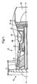
- a ducted fan gas turbine engine generally indicated at 10 comprises, in axial flow series, an air intake 12, a propulsive fan 14, an intermediate pressure compressor 16, a high pressure compressor 18, combustion equipment 20, a high pressure turbine 22, an intermediate pressure turbine 24, a low pressure turbine 26 and an exhaust nozzle 28.
- the gas turbine engine 10 works in the conventional manner so that air entering the intake 12 is accelerated by the fan 14 to produce two air flows, a first air flow into the intermediate pressure compressor 16 and a second airflow which provides propulsive thrust.
- the intermediate pressure compressor 16 compresses the air flow directed into it before delivering the air to the high pressure compressor 18 where further compression takes place.
- the compressed air exhausted from the high pressure compressor 18 is directed into the combustion equipment 20 where it is mixed with fuel and the mixture combusted.
- the resultant hot combustion products then expand through and thereby drive the high, intermediate and low pressure turbines 22, 24 and 26 before being exhausted through the nozzle 28 to provide additional propulsive thrust.
- the high, intermediate and low pressure turbines 22, 24 and 26 respectively drive the high and intermediate pressure compressors 16 and 18 and the fan 14 by suitable interconnecting shafts.
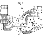
- FIGs 2 to 4 illustrates a turbine seal segment 30 for the high pressure turbine 22.
- a plurality of arc shaped sealing elements in the form of a turbine seal segment together form a substantially cylindrical seal segment ring which encases the rotating high pressure turbine blades 32 (see Figure 2 ).
- a small gap 34 is provided between the tips 36 of the turbine blades 32 and a radially inner surface 33 of the seal segment 30. The size of the gap 34 varies with time for various reasons, including variations in the temperatures of the turbine blades 32 and other components.
- an open cell structure 38 is formed integrally with the turbine seal segment 30 in the region of its radially inner surface 33.
- the open cell structure 38 includes upstanding walls 40 which project radially inwardly.
- the walls 40 define therebetween a plurality of open cells 44, the cells 44 having generally circumferential bases 42.
- the cells 44 are able to receive and support an abradable material 45 such as a metallic powder.
- the cells 44 are generally diamond shaped when viewed in the radial direction of the turbine and the walls are oriented at about 30° to the axial direction of the turbine, in use.
- a first set of generally parallel walls crosses over and intersects a second set of generally parallel walls to form the diamond shaped cells 44.
- the walls 40 may project up to about 3mm radially inwardly from the surface 42.
- the walls 40 have a width of about 0.2mm to 0.4mm and the generally parallel walls are positioned about 2mm to 2.5mm apart.
- the walls are generally rectangular in section, although one skilled in the art would appreciate that other cross-sectional shapes may achieve the same effect.
- Cooling channels 46 are provided within the seal segment 30, radially outwardly of the cell structure 38. Air flowing through the cooling channels helps to cool the cell structure 38 and any abradable material 45 located therein.
- the open cell structure 38 may be formed by laser weld deposition.
- the weld alloy chosen need not be made from the same material as the seal segment 30. In fact there may be advantages in choosing a different material.
- the use of a highly oxidation resistant material to form the cell structure 38 obviates the needs to form the segment 30 from such a material.
- a laser 50 is provided and focused down to provide the required energy density at a working region 52 on the substrate 54.
- Powder 56 is supplied via powder feed tubes 58 to the working region 52.
- the laser 50 and the powder feed tubes 58 are all held static.
- the position and movement of the substrate is controlled by a computer control system 60.
- the focused laser melts the powder 56 and the substrate 54 which mix and solidify when the laser 50 moves to a new position.
- the laser may need to pass over the same region a number of times. Each pass puts down approximately 0.5mm.
- the laser welding equipment and working region 52 are enclosed in a sealed compartment 62 or "glove box" in which the oxygen and moisture level is controlled by a gas purifier 64. This provides a controlled atmosphere, thereby preventing contamination of the weld pool.
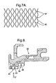
- each zigzag weld line should touch the apex of an adjacent zigzag weld line as it has been shown that such a configuration will enhance structural integrity of such a structure.
- the thickness of the walls 40 may not be constant. In regions where the wall thickness is undersize there will be a gap between apex's of the zigzag lines as indicated at "C" in Figure 7B . Conversely in regions where the wall thickness is oversize the apex of the adjacent zigzag lines will overlap as indicated at "D" in Figure 7C .
- the preferred configuration comprises a wall structure wherein the majority of the zigzag weld line apex's are touching, rather than overlapping or formed with a small gap between the weld line apex's.
- CO 2 laser of type TR1750/380 (Wegmann-Baasel Laser GmbH) used in conjunction with a Sulzer Metco type 9MPE powder feed unit, a X-Y table and Z-axis motor, and a CNC control unit produce the required results.
- the laser 50 is operated in pulse mode, the pulse frequency being set at 1kHz.
- the peak and trough of the pulse is set to 100% and 0% of the setting power respectively.
- it may be required to position a beam expander (not shown) above the focal lens.
- the four tubes were arranged symmetrically and equi-spaced around the laser beam 50, with the angle between each of the tubes 58 and the laser 50 set to 30°.
- the surface of the substrate 54 Prior to deposition the surface of the substrate 54 is scanned with the laser 50 along the paths where the walls 40 are to be built. This action cleans off any contaminants such as oxide film from the surface of the substrate 54, thereby improving the bond between the substrate 54 and the wall 40.
- the substrate 54 is selected from at least one of a group of materials comprising nickel based superalloys, CMSX-4, MM002, C1023 and IN713LC. A man skilled in the art would appreciate that this list is not exhaustive.
- the powder 56 is selected from at least one of a group of materials comprising CM186, Rene 142, Haynes 214 and Amdry 955. A man skilled in the art would appreciate that this list is not exhaustive.
- the powder size used was in the range of 50 ⁇ m to 100 ⁇ m, although it will be appreciated that other powder sizes may prove to have equal utility.
- the cell structure 38 may need to be machined to achieve the desired profile.
- the surfaces of the cells 44 may be nickel plated, and the cells 44 may subsequently be filled with an abradable material 45.
- the cells may be overfilled, such that the abradable material 45 projects radially inwardly beyond the radially inner edges of the walls 40.
- the open cell structure 38 acts as a retention system for the abradable material 45, thus minimising damage to the walls 40.
- the abradable material 45 is selected from at least one of a group of materials comprising Porous YSZ, porous Alumina and hollow NiAl powder. A man skilled in the art would appreciate that this list is not exhaustive.
- the above described embodiment thus provides a turbine seal segment which overcomes many of the problems associated with the prior art.
- the depth of the abradable material 45 may be reduced since extra depth to accommodate wicked braze material is not required.
- the described embodiment has the advantage over electro discharge machining in that having worn away the structure formed by electro discharge machining there is no material available to form a new cell structure 38.
- the described embodiment provides a means for adding material to the seal segment 30.
- the walls of the open cell structure 38 have a relatively high oxidation resistance and are easily cooled because they are positioned near to the cooling channels 46.
- Figure 8 and 9 illustrate an alternative embodiment of the invention, in which corresponding reference numerals are used for equivalent parts.
- the open cell structure 38 includes upstanding walls 40 which define therebetween a plurality of cells.
- a small number of generally diamond shaped cells 44 are located at the outer edges of the seal segment.
- the majority of the cells 144 form elongate rhomboid shapes when viewed in the radial direction of the turbine.
- the width of the walls 40 may however be somewhat increased at their radially inner edges, forming a re-entrant shape, thus helping to prevent abradable material 45 from becoming detached from the cell structure.
- the open cells 38 need not be diamond or rhomboid shaped, but for example may be rectangular, triangular, etc.
- the cells 38 may be discrete as illustrated, or may interconnect with one another.
- a plurality of closely spaced walls or rails, which may be parallel, may form a seal structure.
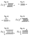
- the walls 40 as shown in figure 10 , are configured at an angle to the longitudinal axis of the engine.
- a cross section through this structure, as shown in figure 11 illustrates overfill of the cell structure 40 with the abradable 45.
- Figure 12 illustrates a cross section of an alternative embodiment wherein the walls 40 are inclined in the direction of travel of the turbine blade 32, as indicated by arrow "B".
- the walls 40 are inclined up to about 30 degrees from the radial direction.
- the walls 40 may be formed in a chevron pattern, with the chevrons orientated circumferentially, as shown in figure 13 .
- This configuration has been found to not only to resist coating loss through thermal shock but also to reduce loss of coating from the rails during blade incursion. Additionally it has been found that the chevron configuration, arranged so that the wall 40 is angled such that it trails behind both the leading and trailing edges of the blade 32, produces a cleaner cut of the blade 32 than were the wall 40 angled forwards.
- An arc arrangement as shown in figure 14 would produce the same effect.
- a configuration where the walls 40 are provided substantially circumferentially around the radially inner surface of the sealing element, that is to say normal to the blade direction as in figure 15 will also produce a clean cut of the blade 32.
- seal structure 38 may form the seal with no additional sealing material being used.
- the weld alloy, and consequently the cell walls 40, may be utilised as an abradable.
- electro-chemical machining or etching may be used to reduce the thickness of the walls 40 in the sealing structure 38.
- the method of producing the projecting walls 40 can also be employed to restore or refurbish thin wall abradable grids that have deteriorated in service.
Claims (14)
- Procédé de fabrication d'un élément d'étanchéité destiné à positionner radialement vers l'extérieur au moins certaines des aubes profilées (32) dans un turbomoteur (10), le procédé comprenant :la formation d'une structure d'étanchéité (38) présentant une zone de surface radialement interne (33) ;la formation d'une pluralité de parois en saillie (40) au niveau de la zone de surface radialement interne (33) pour former une pluralité de cellules ouvertes (44) ;
caractérisé en ce quelesdites parois en saillie (40) sont formées pour présenter une épaisseur allant jusqu'à environ 0,4 mm,et sont formées par dépôt de soudure au laser alimentée en poudre. - Procédé selon la revendication 1, caractérisé en ce que la formation de la structure d'étanchéité (38) comprend la formation d'une structure d'étanchéité (38) configurée pour faire au moins partie d'un boîtier généralement annulaire.
- Procédé selon la revendication 1 ou la revendication 2, caractérisé en ce que les parois (40) sont formées pour se projeter sensiblement radialement vers l'intérieur depuis la zone de- surface radialement interne (33).
- Procédé selon la revendication 1 ou 2 dans lequel les parois (40) sont formées pour se projeter vers l'intérieur suivant un angle allant jusqu'à environ 30 degrés depuis la direction radiale.
- Procédé selon l'une quelconque des revendications précédentes, caractérisé en ce que les bords radialement internes des parois sont formés pour définir une face interne sensiblement en forme d'arc de l'élément d'étanchéité.
- Procédé selon l'une quelconque des revendications précédentes, caractérisé en ce que la structure d'étanchéité (38) est formée au-dessus de sensiblement l'ensemble d'une zone de surface radialement interne (33) de l'élément d'étanchéité.
- Procédé selon l'une quelconque des revendications précédentes, caractérisé en ce qu'au moins une des parois en saillie (4) est formée pour présenter une épaisseur qui diminue généralement en direction d'un bord radialement interne de la au moins une paroi en saillie (40).
- Procédé selon l'une quelconque des revendications 1 à 6, caractérisé en ce qu'au moins une des parois en saillie est formée pour présenter une épaisseur qui diminue en direction d'un bord radialement interne de la au moins une paroi en saillie (40).
- Procédé selon l'une quelconque des revendications précédentes, caractérisé en ce que chaque cellule (44) est ouverte uniquement au niveau d'un côté radialement interne.
- Procédé selon l'une quelconque des revendications précédentes, caractérisé en ce qu'une ou plusieurs des cellules (44) est façonnée sensiblement en forme de diamant vu dans la direction radiale.
- Procédé selon l'une quelconque des revendications précédentes dans lequel les parois se projetant vers l'intérieur (40) sont formées suivant un modèle de chevron.
- Procédé selon l'une quelconque des revendications précédentes dans lequel les parois se projetant vers l'intérieur (40) sont formées suivant une configuration arquée.
- Procédé selon l'une quelconque des revendications précédentes dans lequel les parois se projetant vers l'intérieur (40) sont formées pour présenter une hauteur allant jusqu'à environ 3 mm.
- Procédé selon l'une quelconque des revendications précédentes dans lequel les parois se projetant vers l'intérieur (40) sont formées pour être espacées d'environ 2 mm les unes des autres.
Applications Claiming Priority (2)
| Application Number | Priority Date | Filing Date | Title |
|---|---|---|---|
| GB0304546 | 2003-02-27 | ||
| GB0304546A GB0304546D0 (en) | 2003-02-27 | 2003-02-27 | Abradable seals |
Publications (3)
| Publication Number | Publication Date |
|---|---|
| EP1452696A2 EP1452696A2 (fr) | 2004-09-01 |
| EP1452696A3 EP1452696A3 (fr) | 2006-10-04 |
| EP1452696B1 true EP1452696B1 (fr) | 2008-03-19 |
Family
ID=9953804
Family Applications (1)
| Application Number | Title | Priority Date | Filing Date |
|---|---|---|---|
| EP20030258005 Expired - Lifetime EP1452696B1 (fr) | 2003-02-27 | 2003-12-18 | Procéde de fabrication d'un élément d'étanchéité |
Country Status (3)
| Country | Link |
|---|---|
| EP (1) | EP1452696B1 (fr) |
| DE (1) | DE60319797T2 (fr) |
| GB (2) | GB0304546D0 (fr) |
Families Citing this family (9)
| Publication number | Priority date | Publication date | Assignee | Title |
|---|---|---|---|---|
| DE102010062087A1 (de) | 2010-11-29 | 2012-05-31 | Siemens Aktiengesellschaft | Strömungsmaschine mit Dichtstruktur zwischen drehenden und ortsfesten Teilen sowie Verfahren zur Herstellung dieser Dichtstruktur |
| GB2489693B (en) | 2011-04-04 | 2014-10-01 | Rolls Royce Plc | Abradable liner |
| DE102012200883B4 (de) * | 2012-01-23 | 2015-12-03 | MTU Aero Engines AG | Strömungsmaschinen-Dichtungsanordnung |
| FR3007065B1 (fr) * | 2013-06-14 | 2017-11-10 | Snecma | Anneau abradable pour turbomachine |
| CN106030045B (zh) * | 2014-02-25 | 2017-10-03 | 西门子公司 | 具有带有复合角、不对称表面面积密度脊和槽样式的耐磨层的涡轮环形节段 |
| US9243511B2 (en) | 2014-02-25 | 2016-01-26 | Siemens Aktiengesellschaft | Turbine abradable layer with zig zag groove pattern |
| GB201417307D0 (en) | 2014-10-01 | 2014-11-12 | Rolls Royce Plc | Sealing element |
| DE102015216208A1 (de) | 2015-08-25 | 2017-03-02 | Rolls-Royce Deutschland Ltd & Co Kg | Dichtelement für eine Turbomaschine, Turbomaschine mit einem Dichtelement und Verfahren zur Herstellung eines Dichtelementes |
| GB201916958D0 (en) | 2019-11-21 | 2020-01-08 | Rolls Royce Plc | Abradable sealing element |
Family Cites Families (10)
| Publication number | Priority date | Publication date | Assignee | Title |
|---|---|---|---|---|
| US3126149A (en) * | 1964-03-24 | Foamed aluminum honeycomb motor | ||
| US3042365A (en) * | 1957-11-08 | 1962-07-03 | Gen Motors Corp | Blade shrouding |
| CA963497A (en) * | 1970-12-21 | 1975-02-25 | Gould Inc. | Powder metal honeycomb |
| US4764089A (en) * | 1986-08-07 | 1988-08-16 | Allied-Signal Inc. | Abradable strain-tolerant ceramic coated turbine shroud |
| US5160822A (en) * | 1991-05-14 | 1992-11-03 | General Electric Company | Method for depositing material on the tip of a gas turbine engine airfoil using linear translational welding |
| US5453329A (en) * | 1992-06-08 | 1995-09-26 | Quantum Laser Corporation | Method for laser cladding thermally insulated abrasive particles to a substrate, and clad substrate formed thereby |
| US5584663A (en) * | 1994-08-15 | 1996-12-17 | General Electric Company | Environmentally-resistant turbine blade tip |
| US5704759A (en) * | 1996-10-21 | 1998-01-06 | Alliedsignal Inc. | Abrasive tip/abradable shroud system and method for gas turbine compressor clearance control |
| US5951892A (en) * | 1996-12-10 | 1999-09-14 | Chromalloy Gas Turbine Corporation | Method of making an abradable seal by laser cutting |
| GB0008892D0 (en) * | 2000-04-12 | 2000-05-31 | Rolls Royce Plc | Abradable seals |
-
2003
- 2003-02-27 GB GB0304546A patent/GB0304546D0/en not_active Ceased
- 2003-12-16 GB GB0329085A patent/GB2398844B/en not_active Expired - Lifetime
- 2003-12-18 DE DE2003619797 patent/DE60319797T2/de not_active Expired - Lifetime
- 2003-12-18 EP EP20030258005 patent/EP1452696B1/fr not_active Expired - Lifetime
Also Published As
| Publication number | Publication date |
|---|---|
| GB0329085D0 (en) | 2004-01-14 |
| DE60319797T2 (de) | 2009-04-23 |
| EP1452696A3 (fr) | 2006-10-04 |
| GB2398844B (en) | 2005-04-13 |
| GB2398844A (en) | 2004-09-01 |
| GB0304546D0 (en) | 2003-04-02 |
| DE60319797D1 (de) | 2008-04-30 |
| EP1452696A2 (fr) | 2004-09-01 |
Similar Documents
| Publication | Publication Date | Title |
|---|---|---|
| US7029232B2 (en) | Abradable seals | |
| EP3002417B1 (fr) | Élément de joint | |
| EP3415718B1 (fr) | Composants de moteur à turbine à gaz comportant des caractéristiques de refroidissement par air et leurs procédés de fabrication associés | |
| EP1013788B1 (fr) | Réparation des anneaux de cerclage à haute pression de turbine | |
| EP2578720B1 (fr) | Procédés de réparation de composants refroidis | |
| EP2495397B1 (fr) | Procédés pour réparer des composants de turbine | |
| EP3617451B1 (fr) | Aube à élément poreux abradable et procédé d'usinage associé | |
| US6644914B2 (en) | Abradable seals | |
| US10718352B2 (en) | Multi-cellular abradable liner | |
| US20170009584A1 (en) | Systems and Methods for Turbine Blade Repair | |
| EP3062021A1 (fr) | Appareil à buse à combustible remplaçable, système et procédé | |
| EP3284916B1 (fr) | Composant pour un moteur à turbine à gaz et procédé de fabrication | |
| CN106194434B (zh) | 用于涡轮发动机的构件及形成其的方法和涡轮发动机 | |
| EP1452696B1 (fr) | Procéde de fabrication d'un élément d'étanchéité | |
| EP0361655B1 (fr) | Procédé de construction d'un joint d'étanchéité pour aube de turbine | |
| US20110217484A1 (en) | Method for repairing seal segments of rotor/stator seals of a gas turbine | |
| JP6947851B2 (ja) | スキーラ先端を備えるタービンブレードおよび高密度酸化物分散強化層 | |
| US20220213583A1 (en) | Process for coating substrates with aperture(s) | |
| CN110712002A (zh) | 恢复叶片或导叶平台的方法 | |
| US11674405B2 (en) | Abradable insert with lattice structure | |
| EP3851643B1 (fr) | Distributeur de turbine comprenant un joint élastique et son procédé de fabrication additive | |
| EP3825522A1 (fr) | Élément d'étanchéité abradable et procédé de fabrication d'un élément d'étanchéité abradable | |
| EP3351739B1 (fr) | Élément d'étanchéité et son procédé de fabrication | |
| EP3702585B1 (fr) | Système et procédé de revêtement en céramique |
Legal Events
| Date | Code | Title | Description |
|---|---|---|---|
| PUAI | Public reference made under article 153(3) epc to a published international application that has entered the european phase |
Free format text: ORIGINAL CODE: 0009012 |
|
| AK | Designated contracting states |
Kind code of ref document: A2 Designated state(s): AT BE BG CH CY CZ DE DK EE ES FI FR GB GR HU IE IT LI LU MC NL PT RO SE SI SK TR |
|
| AX | Request for extension of the european patent |
Extension state: AL LT LV MK |
|
| PUAL | Search report despatched |
Free format text: ORIGINAL CODE: 0009013 |
|
| AK | Designated contracting states |
Kind code of ref document: A3 Designated state(s): AT BE BG CH CY CZ DE DK EE ES FI FR GB GR HU IE IT LI LU MC NL PT RO SE SI SK TR |
|
| AX | Request for extension of the european patent |
Extension state: AL LT LV MK |
|
| 17P | Request for examination filed |
Effective date: 20070127 |
|
| AKX | Designation fees paid |
Designated state(s): DE FR |
|
| 17Q | First examination report despatched |
Effective date: 20070619 |
|
| GRAP | Despatch of communication of intention to grant a patent |
Free format text: ORIGINAL CODE: EPIDOSNIGR1 |
|
| RTI1 | Title (correction) |
Free format text: A METHOD OF MANUFACTURING A SEALING ELEMENT |
|
| GRAS | Grant fee paid |
Free format text: ORIGINAL CODE: EPIDOSNIGR3 |
|
| GRAA | (expected) grant |
Free format text: ORIGINAL CODE: 0009210 |
|
| AK | Designated contracting states |
Kind code of ref document: B1 Designated state(s): DE FR |
|
| REF | Corresponds to: |
Ref document number: 60319797 Country of ref document: DE Date of ref document: 20080430 Kind code of ref document: P |
|
| ET | Fr: translation filed | ||
| PLBE | No opposition filed within time limit |
Free format text: ORIGINAL CODE: 0009261 |
|
| STAA | Information on the status of an ep patent application or granted ep patent |
Free format text: STATUS: NO OPPOSITION FILED WITHIN TIME LIMIT |
|
| 26N | No opposition filed |
Effective date: 20081222 |
|
| REG | Reference to a national code |
Ref country code: DE Ref legal event code: R082 Ref document number: 60319797 Country of ref document: DE Representative=s name: FLEUCHAUS & GALLO PARTNERSCHAFT MBB, DE |
|
| REG | Reference to a national code |
Ref country code: FR Ref legal event code: PLFP Year of fee payment: 13 |
|
| REG | Reference to a national code |
Ref country code: FR Ref legal event code: PLFP Year of fee payment: 14 |
|
| REG | Reference to a national code |
Ref country code: FR Ref legal event code: CA Effective date: 20170517 |
|
| REG | Reference to a national code |
Ref country code: FR Ref legal event code: PLFP Year of fee payment: 15 |
|
| PGFP | Annual fee paid to national office [announced via postgrant information from national office to epo] |
Ref country code: DE Payment date: 20210224 Year of fee payment: 18 |
|
| REG | Reference to a national code |
Ref country code: DE Ref legal event code: R119 Ref document number: 60319797 Country of ref document: DE |
|
| PG25 | Lapsed in a contracting state [announced via postgrant information from national office to epo] |
Ref country code: DE Free format text: LAPSE BECAUSE OF NON-PAYMENT OF DUE FEES Effective date: 20220701 |
|
| PGFP | Annual fee paid to national office [announced via postgrant information from national office to epo] |
Ref country code: FR Payment date: 20221222 Year of fee payment: 20 |
|
| P01 | Opt-out of the competence of the unified patent court (upc) registered |
Effective date: 20230528 |