EP1145879B1 - Véhicule comportant une suspension verticale, dans le plan de la roue à une variation de carrossage - Google Patents
Véhicule comportant une suspension verticale, dans le plan de la roue à une variation de carrossage Download PDFInfo
- Publication number
- EP1145879B1 EP1145879B1 EP01107977A EP01107977A EP1145879B1 EP 1145879 B1 EP1145879 B1 EP 1145879B1 EP 01107977 A EP01107977 A EP 01107977A EP 01107977 A EP01107977 A EP 01107977A EP 1145879 B1 EP1145879 B1 EP 1145879B1
- Authority
- EP
- European Patent Office
- Prior art keywords
- chassis
- camber
- wheel
- transfer arm
- load transfer
- Prior art date
- Legal status (The legal status is an assumption and is not a legal conclusion. Google has not performed a legal analysis and makes no representation as to the accuracy of the status listed.)
- Expired - Lifetime
Links
- 239000000725 suspension Substances 0.000 title claims description 36
- 238000012546 transfer Methods 0.000 claims description 28
- 230000001133 acceleration Effects 0.000 claims description 4
- 238000011156 evaluation Methods 0.000 claims description 3
- 238000005096 rolling process Methods 0.000 claims description 2
- 230000001360 synchronised effect Effects 0.000 claims description 2
- 241000826860 Trapezium Species 0.000 claims 1
- 230000010355 oscillation Effects 0.000 claims 1
- 230000007246 mechanism Effects 0.000 description 6
- 230000006870 function Effects 0.000 description 4
- 230000002349 favourable effect Effects 0.000 description 3
- 210000000056 organ Anatomy 0.000 description 3
- 230000008859 change Effects 0.000 description 2
- 230000006835 compression Effects 0.000 description 2
- 238000007906 compression Methods 0.000 description 2
- 238000002513 implantation Methods 0.000 description 2
- 239000006096 absorbing agent Substances 0.000 description 1
- 230000009471 action Effects 0.000 description 1
- 230000006978 adaptation Effects 0.000 description 1
- 238000013459 approach Methods 0.000 description 1
- 238000012550 audit Methods 0.000 description 1
- 238000006243 chemical reaction Methods 0.000 description 1
- 238000012937 correction Methods 0.000 description 1
- 238000013016 damping Methods 0.000 description 1
- 230000001627 detrimental effect Effects 0.000 description 1
- 238000006073 displacement reaction Methods 0.000 description 1
- 230000000694 effects Effects 0.000 description 1
- 238000001914 filtration Methods 0.000 description 1
- 230000005484 gravity Effects 0.000 description 1
- 230000002427 irreversible effect Effects 0.000 description 1
- 238000012423 maintenance Methods 0.000 description 1
- 238000005259 measurement Methods 0.000 description 1
- 238000000034 method Methods 0.000 description 1
- 238000012986 modification Methods 0.000 description 1
- 230000004048 modification Effects 0.000 description 1
- 230000008520 organization Effects 0.000 description 1
- 230000008447 perception Effects 0.000 description 1
- 230000000284 resting effect Effects 0.000 description 1
- 239000011435 rock Substances 0.000 description 1
- 230000035939 shock Effects 0.000 description 1
- 238000013519 translation Methods 0.000 description 1
Images


Classifications
-
- B—PERFORMING OPERATIONS; TRANSPORTING
- B60—VEHICLES IN GENERAL
- B60G—VEHICLE SUSPENSION ARRANGEMENTS
- B60G17/00—Resilient suspensions having means for adjusting the spring or vibration-damper characteristics, for regulating the distance between a supporting surface and a sprung part of vehicle or for locking suspension during use to meet varying vehicular or surface conditions, e.g. due to speed or load
- B60G17/015—Resilient suspensions having means for adjusting the spring or vibration-damper characteristics, for regulating the distance between a supporting surface and a sprung part of vehicle or for locking suspension during use to meet varying vehicular or surface conditions, e.g. due to speed or load the regulating means comprising electric or electronic elements
- B60G17/016—Resilient suspensions having means for adjusting the spring or vibration-damper characteristics, for regulating the distance between a supporting surface and a sprung part of vehicle or for locking suspension during use to meet varying vehicular or surface conditions, e.g. due to speed or load the regulating means comprising electric or electronic elements characterised by their responsiveness, when the vehicle is travelling, to specific motion, a specific condition, or driver input
- B60G17/0162—Resilient suspensions having means for adjusting the spring or vibration-damper characteristics, for regulating the distance between a supporting surface and a sprung part of vehicle or for locking suspension during use to meet varying vehicular or surface conditions, e.g. due to speed or load the regulating means comprising electric or electronic elements characterised by their responsiveness, when the vehicle is travelling, to specific motion, a specific condition, or driver input mainly during a motion involving steering operation, e.g. cornering, overtaking
-
- B—PERFORMING OPERATIONS; TRANSPORTING
- B60—VEHICLES IN GENERAL
- B60G—VEHICLE SUSPENSION ARRANGEMENTS
- B60G21/00—Interconnection systems for two or more resiliently-suspended wheels, e.g. for stabilising a vehicle body with respect to acceleration, deceleration or centrifugal forces
- B60G21/007—Interconnection systems for two or more resiliently-suspended wheels, e.g. for stabilising a vehicle body with respect to acceleration, deceleration or centrifugal forces means for adjusting the wheel inclination
-
- B—PERFORMING OPERATIONS; TRANSPORTING
- B60—VEHICLES IN GENERAL
- B60G—VEHICLE SUSPENSION ARRANGEMENTS
- B60G3/00—Resilient suspensions for a single wheel
- B60G3/01—Resilient suspensions for a single wheel the wheel being mounted for sliding movement, e.g. in or on a vertical guide
-
- B—PERFORMING OPERATIONS; TRANSPORTING
- B60—VEHICLES IN GENERAL
- B60G—VEHICLE SUSPENSION ARRANGEMENTS
- B60G7/00—Pivoted suspension arms; Accessories thereof
- B60G7/001—Suspension arms, e.g. constructional features
-
- B—PERFORMING OPERATIONS; TRANSPORTING
- B62—LAND VEHICLES FOR TRAVELLING OTHERWISE THAN ON RAILS
- B62D—MOTOR VEHICLES; TRAILERS
- B62D17/00—Means on vehicles for adjusting camber, castor, or toe-in
-
- B—PERFORMING OPERATIONS; TRANSPORTING
- B62—LAND VEHICLES FOR TRAVELLING OTHERWISE THAN ON RAILS
- B62D—MOTOR VEHICLES; TRAILERS
- B62D9/00—Steering deflectable wheels not otherwise provided for
- B62D9/02—Steering deflectable wheels not otherwise provided for combined with means for inwardly inclining vehicle body on bends
-
- B—PERFORMING OPERATIONS; TRANSPORTING
- B60—VEHICLES IN GENERAL
- B60G—VEHICLE SUSPENSION ARRANGEMENTS
- B60G2200/00—Indexing codes relating to suspension types
- B60G2200/10—Independent suspensions
- B60G2200/14—Independent suspensions with lateral arms
- B60G2200/144—Independent suspensions with lateral arms with two lateral arms forming a parallelogram
-
- B—PERFORMING OPERATIONS; TRANSPORTING
- B60—VEHICLES IN GENERAL
- B60G—VEHICLE SUSPENSION ARRANGEMENTS
- B60G2200/00—Indexing codes relating to suspension types
- B60G2200/40—Indexing codes relating to the wheels in the suspensions
- B60G2200/44—Indexing codes relating to the wheels in the suspensions steerable
-
- B—PERFORMING OPERATIONS; TRANSPORTING
- B60—VEHICLES IN GENERAL
- B60G—VEHICLE SUSPENSION ARRANGEMENTS
- B60G2200/00—Indexing codes relating to suspension types
- B60G2200/40—Indexing codes relating to the wheels in the suspensions
- B60G2200/46—Indexing codes relating to the wheels in the suspensions camber angle
-
- B—PERFORMING OPERATIONS; TRANSPORTING
- B60—VEHICLES IN GENERAL
- B60G—VEHICLE SUSPENSION ARRANGEMENTS
- B60G2200/00—Indexing codes relating to suspension types
- B60G2200/40—Indexing codes relating to the wheels in the suspensions
- B60G2200/462—Toe-in/out
-
- B—PERFORMING OPERATIONS; TRANSPORTING
- B60—VEHICLES IN GENERAL
- B60G—VEHICLE SUSPENSION ARRANGEMENTS
- B60G2200/00—Indexing codes relating to suspension types
- B60G2200/40—Indexing codes relating to the wheels in the suspensions
- B60G2200/464—Caster angle
-
- B—PERFORMING OPERATIONS; TRANSPORTING
- B60—VEHICLES IN GENERAL
- B60G—VEHICLE SUSPENSION ARRANGEMENTS
- B60G2202/00—Indexing codes relating to the type of spring, damper or actuator
- B60G2202/40—Type of actuator
- B60G2202/41—Fluid actuator
- B60G2202/413—Hydraulic actuator
-
- B—PERFORMING OPERATIONS; TRANSPORTING
- B60—VEHICLES IN GENERAL
- B60G—VEHICLE SUSPENSION ARRANGEMENTS
- B60G2204/00—Indexing codes related to suspensions per se or to auxiliary parts
- B60G2204/10—Mounting of suspension elements
- B60G2204/14—Mounting of suspension arms
- B60G2204/143—Mounting of suspension arms on the vehicle body or chassis
-
- B—PERFORMING OPERATIONS; TRANSPORTING
- B60—VEHICLES IN GENERAL
- B60G—VEHICLE SUSPENSION ARRANGEMENTS
- B60G2204/00—Indexing codes related to suspensions per se or to auxiliary parts
- B60G2204/40—Auxiliary suspension parts; Adjustment of suspensions
- B60G2204/421—Pivoted lever mechanisms for mounting suspension elements, e.g. Watt linkage
-
- B—PERFORMING OPERATIONS; TRANSPORTING
- B60—VEHICLES IN GENERAL
- B60G—VEHICLE SUSPENSION ARRANGEMENTS
- B60G2204/00—Indexing codes related to suspensions per se or to auxiliary parts
- B60G2204/40—Auxiliary suspension parts; Adjustment of suspensions
- B60G2204/422—Links for mounting suspension elements
-
- B—PERFORMING OPERATIONS; TRANSPORTING
- B60—VEHICLES IN GENERAL
- B60G—VEHICLE SUSPENSION ARRANGEMENTS
- B60G2204/00—Indexing codes related to suspensions per se or to auxiliary parts
- B60G2204/80—Interactive suspensions; arrangement affecting more than one suspension unit
- B60G2204/82—Interactive suspensions; arrangement affecting more than one suspension unit left and right unit on same axle
-
- B—PERFORMING OPERATIONS; TRANSPORTING
- B60—VEHICLES IN GENERAL
- B60G—VEHICLE SUSPENSION ARRANGEMENTS
- B60G2204/00—Indexing codes related to suspensions per se or to auxiliary parts
- B60G2204/80—Interactive suspensions; arrangement affecting more than one suspension unit
- B60G2204/83—Type of interconnection
- B60G2204/8302—Mechanical
-
- B—PERFORMING OPERATIONS; TRANSPORTING
- B60—VEHICLES IN GENERAL
- B60G—VEHICLE SUSPENSION ARRANGEMENTS
- B60G2206/00—Indexing codes related to the manufacturing of suspensions: constructional features, the materials used, procedures or tools
- B60G2206/01—Constructional features of suspension elements, e.g. arms, dampers, springs
- B60G2206/10—Constructional features of arms
- B60G2206/11—Constructional features of arms the arm being a radius or track or torque or steering rod or stabiliser end link
-
- B—PERFORMING OPERATIONS; TRANSPORTING
- B60—VEHICLES IN GENERAL
- B60G—VEHICLE SUSPENSION ARRANGEMENTS
- B60G2206/00—Indexing codes related to the manufacturing of suspensions: constructional features, the materials used, procedures or tools
- B60G2206/01—Constructional features of suspension elements, e.g. arms, dampers, springs
- B60G2206/10—Constructional features of arms
- B60G2206/11—Constructional features of arms the arm being a radius or track or torque or steering rod or stabiliser end link
- B60G2206/111—Constructional features of arms the arm being a radius or track or torque or steering rod or stabiliser end link of adjustable length
- B60G2206/1114—Self-adjustable during driving
Definitions
- the present invention relates to the ground connection of vehicles, especially vehicles road. It concerns both the guiding of a vehicle wheel relative to the body of this vehicle, as the organization of the wheel travel relative to the chassis. She relates more particularly to means used to control the position of the wheel plane, both in camber with respect to the ground, and in both travel horizontal than vertical to the body.
- the objective of the invention is to provide a high level of security for vehicle operation and great comfort through suspension kinematics allowing both active control of the wheel camber and suspension vertical.
- the objective of the present invention is to achieve, by a more compact arrangement, to provide the same degrees of freedom of movement (and their rigorous controls) of the wheel plane in relation to the ground and in relation to the chassis, while leaving more than space available between the suspension mechanisms, in particular to accommodate the mechanical and / or the passenger compartment.
- the invention provides a vehicle according to claim 1.
- ground connection commonly designates all of the elements between the floor and the body or chassis of a vehicle.
- the invention proposes a kinematics of suspension as pure and as complete as possible: the connection to the ground not only offers a vertical suspension, but in addition it authorizes at any time a modification of the camber of the wheel without reducing the stroke of the vertical suspension neither to compression nor to rebound, and while maintaining the vertical suspension under optimal operating conditions, in particular because controlling the camber angle makes it possible to reduce the moments and shear forces appearing in the guide of the vertical suspension and due to a centrifugal force.
- the invention provides a vehicle with active control of roll: the passenger compartment of the vehicle is mounted on the chassis so that it can tilt towards the inside of the turn depending on the centrifugal force.
- the cockpit takes a more natural roll and is better tolerated by the occupants of the vehicle, like two-wheeled vehicles in line (a motorcycle for example).
- the roll is a measure of the attitude angle of the passenger compartment relative to the ground, we act on the roll angle indirectly, by resting on the chassis of the vehicle.
- the objective is to reach a substantial range of variation in the roll angle of the passenger compartment, of the same order of magnitude as the range of camber variation. In this way, without necessarily reach the roll angles that a two-person vehicle can take wheels aligned, the effect produced is sufficiently noticeable to radically change the impressions felt by the passengers of such a vehicle, and thus contribute to their comfort.
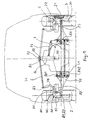
- a frame 1 consisting of a central beam, to which all parts of the vehicle are attached.
- each link to vehicle floor is identical.
- Four wheels 2 are therefore mounted on the chassis 1 by identical organs, which means that it is sufficient to describe only one of the connections to the ground for a full description of the invention.
- a tire 20 whose profile in radial section recalls that of the tires for motorcycles, because the tire has to operate at very camber angles distant from zero degrees.
- Wheel 2 is mounted on a wheel carrier 3 (called “wheel carrier” “the non-rotating member) by means of a hub 21 and a bearing 22, shown schematically on the right side of Figure 1.
- the wheel carrier 3 faithfully follows all the movements of the wheel 2 (except of course the rotation of the wheel around its axis of rotation).
- the wheel carrier 3 is mounted on a support 5, the travel required for the vertical suspension occurring between the support 5 and the wheel carrier 3.
- the wheel carrier 3 is mounted on the support 5 by by means of a single bar 30 sliding in the support 5 and guided by the latter.
- the wheel carrier is immobilized on the bar 30 at the two ends of the latter.
- the bar 30 is disposed in the volume radially delimited by the rim of said wheel 2.
- the suspension travel of a wheel occurs in this case parallel to the wheel plane. You can control the travel of the wheel for example by a spring helical 81 (see Figure 2) and by a shock absorber which can be mounted inside the spring (not shown so as not to overload the drawing). Another solution will be discussed in more detail below.
- the support 5 comprises a first element 51 for guiding the wheel 2 and a second mounting element 52 on which are arranged said three points A1, A2 and A3 for mounting the support 5 on the vehicle.
- the bar 30 slides in the first element 51, which provides the vertical suspension movement, but cannot rotate around its axis geometric independently of the first element 51.
- the first element 51 is mounted in the second element 52 by bearings 53 centered on the axis of the bar 30, no translation parallel to the geometric axis of the bar 30 of the first element 51 relative to the second element 52 is not possible.
- the first element 51 and second element 52 thus form a pivot 50.
- the tab 59 which has been discussed above extends the first element 51 and ends at the command point A3 of the camber of the wheel 2.
- a lever 58 extends the second element 52 and ends in a point A4 for controlling the steering of the wheel 2.
- the steering angle is controlled by a turning rod 75, visible in particular in Figure 2 and on the right side of Figure 1.
- the plate 72 is arranged at the end of a central lever 74 articulated on the chassis 1 at a point located on a roll axis 90, to which we will return later in the description.
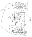
- the transverse movement of the plate 72 relative to the chassis 1 is controlled by a camber cylinder 73, irreversible or braked, the length of which is controlled so appropriate.
- the wheels 2 tilt from the same side, ie not symmetrically with respect to the chassis.
- the load transfer arm 70 is, on the side of the chassis 1, is mounted along a substantially vertical geometric axis AK.
- the arm load transfer 70 can not rotate in the vertical plane ( Figures 1 and 3). from then, the load supported by the chassis 1 is fully transferred to all of the load transfer arm 70.
- the moment around the substantially vertical geometrical axis AK due to the stresses horizontal from the driving and / or braking forces and / or impacts exerted on the wheel.
- the load transfer arm 70 should preferably rest on the chassis 1 at a point distant from the substantially vertical geometric axis AK.
- An element forming triangulation 6 is for this purpose mounted on the one hand on the load transfer arm 70 at an intermediate point 61 between its ends, and on the other hand on the chassis at a distant point 62 of the substantially vertical geometrical axis AK of the transfer arm of charge 70.
- the invention advantageously lends itself to the implantation of a horizontal suspension.
- We can for example mount the load transfer arm 70 at the attachment points AK1 and AK2 superimposed so that it can rotate quite freely around of said substantially vertical geometrical axis AK, which gives a certain latitude of longitudinal movement to support 5, therefore to wheel 2.
- the element forming triangulation 6 to control the horizontal suspension travel of the load transfer arm 70.
- the triangulation element 6 is an element that enjoys of a certain elasticity, allowing (but controlling it) an oscillating movement of the load transfer arm 70 around the substantially vertical geometrical axis AK. It comprises a means providing a spring function and a means providing a damping function.
- a properly formulated rubber element can, as we know, provide these two functions.
- the proposed simplified camber mechanism can accommodate movements of the horizontal suspension, while introducing only camber variations imperceptible.
- the turning rod 75 forms a trapezoid with the transfer arm load 70.
- the length of the turning rod 75 is greater than the length of the load transfer arm 70.
- the turning rod 75 is actuated by a direction control lever 76 mounted articulated on the axis substantially vertical geometrical AK of the load transfer arm 70.
- the end 77 lever 76 terminates in the longitudinal plane ⁇ containing the geometric axis substantially vertical AK.
- the steering control of a steering stop at the other, by a steering bar 78 makes describe at the end 77 of the lever 76 a symmetrical movement with respect to said longitudinal plane ⁇ . It is by this provision that one carries out an order according to the principle of the purity of Jeantaud.
- FIG. 2 the position of the traction motor is shown (in dashed lines). 80 wheel turned to the stop on the right. This is the position to which the reference points "80".
- the load transfer arm 70 is curved so as to release the space required, taking into account the fact that this traction motor 80 accompanies the wheel plane movements in steering and vertical travel movements of the wheel.
- FIG. 3 the position of the suspension motor 82 when the wheels 2 are in camber stop.
- the load transfer arm 70 is formed so as to clear the space necessary, taking into account the fact that this traction motor 80 accompanies the wheel plane movements in turning, camber and travel.
- the load transfer arm 70 and the lug 59 are formed so to free up the necessary space, taking into account the fact that this suspension motor 82 supports the movements of the wheel plane in turning and camber.
- the steering mechanism must make the steering angle of the wheels sufficiently insensitive to camber variations and movement of horizontal suspension (see variations in body roll if this is actively controlled, as proposed below).
- the support 5 is in one piece and the triangulation element 6 is then preferably rigid.
- the wheel plane is held in deflection by the fact that the points A1 and A2 defining the geometric axis of AA camber are sufficiently spaced from each other and are connected to the same part mechanical, namely load transfer arm 70.
- a support 5 in two elements 51 and 52 as described above and the wheel carrier is immobilized by connecting so suitable a link to the lever 58 of the first element 51 on the one hand and to the frame 1 on the other hand. If the support 5 moves back relative to the chassis 1, the second element 52 undergoes a slight rotation, which is automatically compensated for by a slight turning of the first element 51 in the second element 52. This avoids the appearance of a steering induced by the movement of the support along the suspension stroke horizontal.
- the roll control means consist essentially of the camber cylinder 73, so that the camber variation of the wheels 2 and the variation of the roll angle of the passenger compartment are synchronous.
- the cabin takes an angle roll p in the opposite direction to the usual direction for passenger vehicles. it contributes to passenger comfort, including through increased perception security. Note that this also contributes in itself to security, by moving the center of gravity of the vehicle towards the inside of the turn, which reduces the load share transferred to the wheels outside the turn. Not only do the tires work in a more favorable position relative to the ground, but moreover, in this mode of achievement, the momentary tire overload on the outside of the turn is less than if there was no camber correction. The tires on the inside are less shed, and therefore their ability to develop drift thrusts is better preserved.
- At least one can install on the vehicle a sensor for reading the value of at least one parameter allowing an evaluation transverse acceleration acting on the vehicle, calculation means for calculate the amplitude of the camber angle as a function of the value or values recorded.
- the camber angle can be controlled individually wheel by wheel, or collectively for all wheels or for wheels on the same axle.
- the invention applies in particular to four-wheeled vehicles such as passenger cars tourism.
- the variation in camber angle in question here is large magnitude, i.e. closer to the values commonly scanned by motorcycles than adjustment values which may exist in a conventional passenger vehicle, four wheels.
- the range of variation is of the order of ⁇ 15 ° to ⁇ 20 °.
- the variation range is in any case such that, when the wheel rocks around its area contact with the ground, the transverse displacement of the part radially upper wheel can reach a magnitude greater than the width of said wheel.
Landscapes
- Engineering & Computer Science (AREA)
- Mechanical Engineering (AREA)
- Chemical & Material Sciences (AREA)
- Combustion & Propulsion (AREA)
- Transportation (AREA)
- Vehicle Body Suspensions (AREA)
- Steering-Linkage Mechanisms And Four-Wheel Steering (AREA)
Applications Claiming Priority (3)
| Application Number | Priority Date | Filing Date | Title |
|---|---|---|---|
| FR0004596 | 2000-04-10 | ||
| FR0004596A FR2807378A1 (fr) | 2000-04-10 | 2000-04-10 | Vehicule comportant une suspension a une variation de carrossage et suspension verticale dans le plan de la roue |
| US09/922,155 US6511087B1 (en) | 2001-08-06 | 2001-08-06 | Jogging kick scooter |
Publications (2)
| Publication Number | Publication Date |
|---|---|
| EP1145879A1 EP1145879A1 (fr) | 2001-10-17 |
| EP1145879B1 true EP1145879B1 (fr) | 2004-01-21 |
Family
ID=26212336
Family Applications (1)
| Application Number | Title | Priority Date | Filing Date |
|---|---|---|---|
| EP01107977A Expired - Lifetime EP1145879B1 (fr) | 2000-04-10 | 2001-03-29 | Véhicule comportant une suspension verticale, dans le plan de la roue à une variation de carrossage |
Country Status (4)
| Country | Link |
|---|---|
| US (1) | US6511078B2 (https=) |
| EP (1) | EP1145879B1 (https=) |
| JP (1) | JP2002052915A (https=) |
| FR (1) | FR2807378A1 (https=) |
Families Citing this family (55)
| Publication number | Priority date | Publication date | Assignee | Title |
|---|---|---|---|---|
| US6398251B1 (en) * | 1997-01-31 | 2002-06-04 | Dallas Smith Corporation | Axleless vehicle suspension system |
| US7559400B2 (en) | 1997-01-31 | 2009-07-14 | Aloha, Llc | Low profile chassis and suspension |
| US6986519B2 (en) | 1997-01-31 | 2006-01-17 | Aloha, Llc | Low profile chassis and suspension |
| US6967484B2 (en) * | 2000-03-27 | 2005-11-22 | Midtronics, Inc. | Electronic battery tester with automotive scan tool communication |
| WO2002058949A1 (fr) * | 2001-01-23 | 2002-08-01 | Societe De Technologie Michelin | Dispositif de suspension d'une roue de vehicule |
| DE10120918B4 (de) * | 2001-04-27 | 2011-05-05 | Continental Aktiengesellschaft | Elektrisch verstellbare, semiaktive Dämpferregelung |
| WO2003057529A2 (en) * | 2002-01-08 | 2003-07-17 | Hypercar, Inc. | Advanced composite hybrid-electric vehicle |
| KR20040006288A (ko) * | 2002-07-11 | 2004-01-24 | 현대자동차주식회사 | 소형자동차의 리어현가장치 |
| US7246806B2 (en) * | 2002-07-22 | 2007-07-24 | Michelin Recherche Et Technique S.A. | Suspension system for a vehicle wheel |
| DE10304916A1 (de) * | 2003-02-07 | 2004-08-26 | O&K Orenstein & Koppel Ag | Verfahren und Vorrichtung zur Radsturzverstellung |
| US20050017471A1 (en) * | 2003-06-09 | 2005-01-27 | Matthew Kim | Steering with triple linkage suspension having steering adjusted camber |
| WO2005000606A1 (ja) * | 2003-06-30 | 2005-01-06 | Bridgestone Corporation | サスペンション |
| ITTO20030639A1 (it) * | 2003-08-14 | 2005-02-15 | Marco Martina | Dispositivo di stabilizzazione per veicoli. |
| ATE524333T1 (de) * | 2003-08-18 | 2011-09-15 | Michelin Soc Tech | Aufhängungsvorrichtung |
| FR2858964B1 (fr) * | 2003-08-18 | 2005-10-07 | Michelin Soc Tech | Dispositif de suspension permettant une variation de carrossage et vehicule comportant ledit dispositif |
| WO2005039900A2 (en) | 2003-10-24 | 2005-05-06 | Aloha, Llc | Suspensions for low floor vehicles |
| FR2872773B1 (fr) * | 2004-07-07 | 2006-09-29 | Moulene Sarl | Vehicule motorise de faible largeur |
| FR2873061B1 (fr) * | 2004-07-15 | 2008-12-05 | Conception & Dev Michelin Sa | Vehicule comportant une liaison au sol assurant la suspension individuelle des roues, ainsi qu'un controle actif de la hauteur de caisse |
| WO2006062677A2 (en) * | 2004-12-06 | 2006-06-15 | Shumate, David D. | Variable ratio suspension system for autos |
| WO2007041095A2 (en) | 2005-09-30 | 2007-04-12 | Harley-Davidson Motor Company Group, Inc. | Leaning suspension mechanics |
| US7571787B2 (en) | 2005-09-30 | 2009-08-11 | Harley-Davidson Motor Company Group, LLC | Headlight mounting arrangement |
| JP4534944B2 (ja) * | 2005-10-07 | 2010-09-01 | トヨタ自動車株式会社 | 乗り物 |
| WO2007103392A2 (en) * | 2006-03-06 | 2007-09-13 | Purdue Research Foundation | Swinging hub for adjusting wheel camber |
| US20070267883A1 (en) * | 2006-05-19 | 2007-11-22 | Gravititech Llc | Titling Vehicle Frame |
| US7914020B2 (en) * | 2008-01-31 | 2011-03-29 | Roy Boston | Vehicle suspension system with a variable camber system |
| US8818700B2 (en) | 2008-02-29 | 2014-08-26 | Daniel Moulene | Motorised vehicle with controlled inclination |
| FR2928130B1 (fr) * | 2008-02-29 | 2010-05-28 | Moulene | Vehicule motorise a inclinaison commandee. |
| WO2009126787A2 (en) * | 2008-04-10 | 2009-10-15 | Sacli Suspension, Llc | Suspension system providing two degrees of freedom |
| KR100986088B1 (ko) * | 2008-11-11 | 2010-10-07 | 현대자동차주식회사 | 액티브 지오메트리 컨트롤 서스펜션 |
| KR101028058B1 (ko) | 2009-04-06 | 2011-04-08 | 현대로템 주식회사 | 다축 인휠 모터 차량용 자가 정렬 현가 장치 |
| US20100320023A1 (en) * | 2009-06-23 | 2010-12-23 | Michael Rhodig | Four wheel vehicle having a rotatable body section and method therefor |
| CA2714255A1 (en) | 2009-09-01 | 2011-03-01 | Timbren Industries Inc. | Suspension mechanism |
| DK177094B1 (en) * | 2009-09-15 | 2011-08-22 | Ecomove Aps | A transport means and a vehicle |
| US8641064B2 (en) | 2011-12-29 | 2014-02-04 | Garbis Krajekian | Tilting vehicle with a non-tilting automobile-like body |
| DE102014201127B4 (de) | 2013-03-07 | 2022-02-03 | Ford Global Technologies, Llc | Seitlich neigbares, mehrspuriges Fahrzeug |
| DE102014201630B4 (de) | 2013-03-07 | 2021-09-02 | Ford Global Technologies, Llc | Seitlich neigbares, mehrspuriges Fahrzeug |
| DE102014201668B4 (de) | 2013-03-07 | 2021-09-02 | Ford Global Technologies, Llc | Seitlich neigbares, mehrspuriges Fahrzeug |
| DE102014201632B4 (de) | 2013-03-07 | 2021-09-02 | Ford Global Technologies, Llc | Seitlich neigbares, mehrspuriges Fahrzeug |
| DE102014201670A1 (de) | 2013-03-07 | 2014-09-11 | Ford Global Technologies, Llc | Seitlich neigbares, mehrspuriges Fahrzeug |
| RU2607691C1 (ru) * | 2014-05-13 | 2017-01-10 | Текнолоджи Инвестментс Лимитед | Система рулевого управления |
| DE102014217246B3 (de) | 2014-08-29 | 2015-12-24 | Ford Global Technologies, Llc | Stabilisierungsanordnung für ein Neigefahrwerk eines Fahrzeugs |
| DE102014217386B4 (de) | 2014-09-01 | 2024-11-14 | Ford Global Technologies, Llc | Verfahren zum Betrieb eines Neigefahrwerks für ein schienenungebundenes Fahrzeug |
| US10076939B2 (en) | 2014-11-26 | 2018-09-18 | Ford Global Technologies, Llc | Suspension systems for laterally tiltable multitrack vehicles |
| US9925843B2 (en) | 2015-02-24 | 2018-03-27 | Ford Global Technologies, Llc | Rear suspension systems for laterally tiltable multitrack vehicles |
| US10023019B2 (en) | 2015-02-24 | 2018-07-17 | Ford Global Technologies, Llc | Rear suspension systems with rotary devices for laterally tiltable multitrack vehicles |
| DE102015203632A1 (de) * | 2015-03-02 | 2016-09-08 | Zf Friedrichshafen Ag | Einzelradaufhängung mit hohem Lenkwinkel |
| KR101614701B1 (ko) * | 2015-08-05 | 2016-04-25 | 자동차부품연구원 | 차량용 틸팅장치 |
| US10639952B2 (en) * | 2017-12-01 | 2020-05-05 | Mahindra N.A. Tech Center | Vehicle suspension |
| CN110126571B (zh) * | 2019-05-28 | 2021-06-08 | 西南交通大学 | 一种轮毂电机轮胎防侧翻装置 |
| WO2024018404A1 (en) * | 2022-07-20 | 2024-01-25 | Ree Automotive Ltd. | Splayed installation of vehicle corner modules |
| TWI836651B (zh) * | 2022-10-05 | 2024-03-21 | 昕銳智能車輛科技有限公司 | 輪胎定位角度偵測型輪圈蓋裝置、輪胎定位角度偵測警示系統及輪胎定位角度偵測警示方法 |
| US12479235B2 (en) | 2022-11-10 | 2025-11-25 | Shin Ruei Intelligent Vehicle Technology Co., Ltd. | Rim accessory for wheel positioning angle detection, warning system for wheel positioning angle detection and warning method for wheel positioning angle detection |
| JP2024070309A (ja) * | 2022-11-11 | 2024-05-23 | ロベルト・ボッシュ・ゲゼルシャフト・ミト・ベシュレンクテル・ハフツング | ロール制御システム及び車両 |
| CN116750081A (zh) * | 2023-07-31 | 2023-09-15 | 徐州徐工矿业机械有限公司 | 摆动式独立悬架系统、多轴驱动车辆及转向模式控制方法 |
| EP4603308A1 (en) * | 2024-02-13 | 2025-08-20 | Kubota Corporation | Work vehicle comprising a sensor for detecting movement of a height-settable axle |
Family Cites Families (13)
| Publication number | Priority date | Publication date | Assignee | Title |
|---|---|---|---|---|
| US2152938A (en) * | 1936-07-11 | 1939-04-04 | Edward L Welch | Vehicle banking mechanism |
| FR967710A (fr) * | 1948-06-11 | 1950-11-10 | Procédé pour combattre la force centrifuge, dans les virages, sur un véhicule à trois ou quatre roues; et châssis oscillant à centre de gravité déplaçable lors des virages | |
| DE1214100B (de) * | 1956-12-18 | 1966-04-07 | Armin Drechsel | Achs- bzw. Radfuehrungsanordnung fuer Fahrzeuge, insbesondere Kraftfahrzeuge, mit sich nach der Kurveninnenseite neigendem Fahrzeugrumpf |
| US3485506A (en) * | 1967-03-06 | 1969-12-23 | John J Melbar | Vehicle steering apparatus |
| US4159128A (en) * | 1977-11-18 | 1979-06-26 | Ferol B. Blaine | Vehicle suspension system including wheel-tilting mechanism |
| DE2822058A1 (de) * | 1978-05-20 | 1979-11-29 | Porsche Ag | Radaufhaengung eines kraftfahrzeuges |
| US4487429A (en) * | 1982-09-30 | 1984-12-11 | Ruggles Thomas P | Tilting wheel vehicle suspension system |
| US4700972A (en) * | 1985-06-20 | 1987-10-20 | Young Colin G | Computerized, central hydraulic, electronic variable suspension |
| JPS63501357A (ja) * | 1985-11-15 | 1988-05-26 | ジェ−ムス・フィリップス・ロナルド | 自己安定化傾斜式車両 |
| JPS63101114A (ja) * | 1986-10-15 | 1988-05-06 | Honda Motor Co Ltd | 自動車のサスペンシヨン構造 |
| US4796720A (en) * | 1987-09-21 | 1989-01-10 | Bauer John K | Four-wheel steering, leveling and banking for vehicles |
| FR2763300A1 (fr) | 1997-05-16 | 1998-11-20 | Conception & Dev Michelin Sa | Vehicule comportant une suspension a variation de carrossage actif |
| FR2763284A1 (fr) | 1997-05-16 | 1998-11-20 | Conception & Dev Michelin Sa | Ensemble comportant une roue et une suspension integree a la roue |
-
2000
- 2000-04-10 FR FR0004596A patent/FR2807378A1/fr active Pending
-
2001
- 2001-03-29 EP EP01107977A patent/EP1145879B1/fr not_active Expired - Lifetime
- 2001-04-09 US US09/829,058 patent/US6511078B2/en not_active Expired - Lifetime
- 2001-04-10 JP JP2001111443A patent/JP2002052915A/ja active Pending
Also Published As
| Publication number | Publication date |
|---|---|
| US20010028154A1 (en) | 2001-10-11 |
| FR2807378A1 (fr) | 2001-10-12 |
| JP2002052915A (ja) | 2002-02-19 |
| EP1145879A1 (fr) | 2001-10-17 |
| US6511078B2 (en) | 2003-01-28 |
Similar Documents
| Publication | Publication Date | Title |
|---|---|---|
| EP1145879B1 (fr) | Véhicule comportant une suspension verticale, dans le plan de la roue à une variation de carrossage | |
| EP1125828B1 (fr) | Véhicule comportant une suspension à variation de carrossage actif | |
| EP1247663B1 (fr) | Véhicule comportant une suspension à variation de carrossage | |
| EP1070609B1 (fr) | Véhicule automobile équipé d'un système de contrôle de l'angle de carrossage des roues du véhicule en virage | |
| EP1276656B1 (fr) | Dispositif de support d'une roue et dispositif de suspension comprenant ledit dispositif de support | |
| EP1363795B1 (fr) | Dispositif de suspension d'une roue de vehicule | |
| EP1616731B1 (fr) | Véhicule comportant une liaison au sol assurant la suspension individuelle des roues, ainsi qu'un contrôle actif de la hauteur de caisse | |
| EP1765615B1 (fr) | Dispositif de suspension pour vehicule automobile | |
| WO2004058521A1 (fr) | Dispositif de support de roue a triple charnière, dispositif de suspension et véhicule comprenant ledit dispositif de support | |
| EP1551652A1 (fr) | Dispositif de suspension d'une roue de vehicule | |
| FR2833233A1 (fr) | Dispositif de suspension d'une roue | |
| EP1572475B1 (fr) | Dispositif de support;une roue, dispositif de suspension et vehicule comprenant ledit dispositif de support | |
| FR2891197A1 (fr) | Dispositif de suspension pour vehicule | |
| WO2006129020A1 (fr) | Vehicule routier a habitacle pendulaire | |
| CA2021553C (fr) | Cadre de side-car pour motocyclette | |
| EP4339084A1 (fr) | Véhicule tricycle | |
| FR2675431A1 (fr) | Dispositif de suspension de vehicule a jambe articulee. | |
| EP1996415B1 (fr) | Véhicule à dispositif de suspension à variation de carrossage. | |
| FR2752213A1 (fr) | Perfectionnement pour chassis de vehicule | |
| FR2878495A1 (fr) | Dispositif de suspension et de direction constituant un train avant de vehicule a deux roues | |
| FR3152484A1 (fr) | Dispositif de suspension arrière de trottinette et trottinette équipée d’un tel dispositif | |
| FR2823149A1 (fr) | Dispositif de suspension permettant le carrossage | |
| FR2999143A1 (fr) | Vehicule equipe d'un train directeur a geometrie amelioree | |
| FR2833234A1 (fr) | Dispositif de suspension permettant le carrossage | |
| FR2819753A1 (fr) | Dispositif de suspension d'une roue de vehicule |
Legal Events
| Date | Code | Title | Description |
|---|---|---|---|
| PUAI | Public reference made under article 153(3) epc to a published international application that has entered the european phase |
Free format text: ORIGINAL CODE: 0009012 |
|
| AK | Designated contracting states |
Kind code of ref document: A1 Designated state(s): AT BE CH CY DE DK ES FI FR GB GR IE IT LI LU MC NL PT SE TR |
|
| AX | Request for extension of the european patent |
Free format text: AL;LT;LV;MK;RO;SI |
|
| 17P | Request for examination filed |
Effective date: 20020417 |
|
| AKX | Designation fees paid |
Free format text: AT BE CH CY DE DK ES FI FR GB GR IE IT LI LU MC NL PT SE TR |
|
| GRAH | Despatch of communication of intention to grant a patent |
Free format text: ORIGINAL CODE: EPIDOS IGRA |
|
| GRAS | Grant fee paid |
Free format text: ORIGINAL CODE: EPIDOSNIGR3 |
|
| GRAA | (expected) grant |
Free format text: ORIGINAL CODE: 0009210 |
|
| AK | Designated contracting states |
Kind code of ref document: B1 Designated state(s): AT BE CH CY DE DK ES FI FR GB GR IE IT LI LU MC NL PT SE TR |
|
| PG25 | Lapsed in a contracting state [announced via postgrant information from national office to epo] |
Ref country code: IE Free format text: LAPSE BECAUSE OF FAILURE TO SUBMIT A TRANSLATION OF THE DESCRIPTION OR TO PAY THE FEE WITHIN THE PRESCRIBED TIME-LIMIT Effective date: 20040121 Ref country code: TR Free format text: LAPSE BECAUSE OF FAILURE TO SUBMIT A TRANSLATION OF THE DESCRIPTION OR TO PAY THE FEE WITHIN THE PRESCRIBED TIME-LIMIT Effective date: 20040121 Ref country code: FI Free format text: LAPSE BECAUSE OF FAILURE TO SUBMIT A TRANSLATION OF THE DESCRIPTION OR TO PAY THE FEE WITHIN THE PRESCRIBED TIME-LIMIT Effective date: 20040121 Ref country code: NL Free format text: LAPSE BECAUSE OF FAILURE TO SUBMIT A TRANSLATION OF THE DESCRIPTION OR TO PAY THE FEE WITHIN THE PRESCRIBED TIME-LIMIT Effective date: 20040121 Ref country code: ES Free format text: LAPSE BECAUSE OF FAILURE TO SUBMIT A TRANSLATION OF THE DESCRIPTION OR TO PAY THE FEE WITHIN THE PRESCRIBED TIME-LIMIT Effective date: 20040121 Ref country code: CY Free format text: LAPSE BECAUSE OF FAILURE TO SUBMIT A TRANSLATION OF THE DESCRIPTION OR TO PAY THE FEE WITHIN THE PRESCRIBED TIME-LIMIT Effective date: 20040121 Ref country code: AT Free format text: LAPSE BECAUSE OF FAILURE TO SUBMIT A TRANSLATION OF THE DESCRIPTION OR TO PAY THE FEE WITHIN THE PRESCRIBED TIME-LIMIT Effective date: 20040121 |
|
| REG | Reference to a national code |
Ref country code: GB Ref legal event code: FG4D Free format text: NOT ENGLISH |
|
| REG | Reference to a national code |
Ref country code: CH Ref legal event code: EP |
|
| REG | Reference to a national code |
Ref country code: IE Ref legal event code: FG4D Free format text: FRENCH |
|
| REF | Corresponds to: |
Ref document number: 60101809 Country of ref document: DE Date of ref document: 20040226 Kind code of ref document: P |
|
| PG25 | Lapsed in a contracting state [announced via postgrant information from national office to epo] |
Ref country code: LU Free format text: LAPSE BECAUSE OF NON-PAYMENT OF DUE FEES Effective date: 20040329 |
|
| PG25 | Lapsed in a contracting state [announced via postgrant information from national office to epo] |
Ref country code: MC Free format text: LAPSE BECAUSE OF NON-PAYMENT OF DUE FEES Effective date: 20040331 Ref country code: BE Free format text: LAPSE BECAUSE OF NON-PAYMENT OF DUE FEES Effective date: 20040331 |
|
| PG25 | Lapsed in a contracting state [announced via postgrant information from national office to epo] |
Ref country code: DK Free format text: LAPSE BECAUSE OF FAILURE TO SUBMIT A TRANSLATION OF THE DESCRIPTION OR TO PAY THE FEE WITHIN THE PRESCRIBED TIME-LIMIT Effective date: 20040421 Ref country code: SE Free format text: LAPSE BECAUSE OF FAILURE TO SUBMIT A TRANSLATION OF THE DESCRIPTION OR TO PAY THE FEE WITHIN THE PRESCRIBED TIME-LIMIT Effective date: 20040421 Ref country code: GR Free format text: LAPSE BECAUSE OF FAILURE TO SUBMIT A TRANSLATION OF THE DESCRIPTION OR TO PAY THE FEE WITHIN THE PRESCRIBED TIME-LIMIT Effective date: 20040421 |
|
| GBT | Gb: translation of ep patent filed (gb section 77(6)(a)/1977) |
Effective date: 20040422 |
|
| NLV1 | Nl: lapsed or annulled due to failure to fulfill the requirements of art. 29p and 29m of the patents act | ||
| REG | Reference to a national code |
Ref country code: IE Ref legal event code: FD4D |
|
| BERE | Be: lapsed |
Owner name: CONCEPTION ET DEVELOPPEMENT MICHELIN S.A. Effective date: 20040331 |
|
| PLBE | No opposition filed within time limit |
Free format text: ORIGINAL CODE: 0009261 |
|
| STAA | Information on the status of an ep patent application or granted ep patent |
Free format text: STATUS: NO OPPOSITION FILED WITHIN TIME LIMIT |
|
| 26N | No opposition filed |
Effective date: 20041022 |
|
| REG | Reference to a national code |
Ref country code: FR Ref legal event code: TP |
|
| PG25 | Lapsed in a contracting state [announced via postgrant information from national office to epo] |
Ref country code: PT Free format text: LAPSE BECAUSE OF NON-PAYMENT OF DUE FEES Effective date: 20040621 |
|
| PGFP | Annual fee paid to national office [announced via postgrant information from national office to epo] |
Ref country code: CH Payment date: 20080314 Year of fee payment: 8 |
|
| PGFP | Annual fee paid to national office [announced via postgrant information from national office to epo] |
Ref country code: GB Payment date: 20080320 Year of fee payment: 8 |
|
| REG | Reference to a national code |
Ref country code: CH Ref legal event code: PL |
|
| GBPC | Gb: european patent ceased through non-payment of renewal fee |
Effective date: 20090329 |
|
| PG25 | Lapsed in a contracting state [announced via postgrant information from national office to epo] |
Ref country code: LI Free format text: LAPSE BECAUSE OF NON-PAYMENT OF DUE FEES Effective date: 20090331 Ref country code: CH Free format text: LAPSE BECAUSE OF NON-PAYMENT OF DUE FEES Effective date: 20090331 |
|
| PG25 | Lapsed in a contracting state [announced via postgrant information from national office to epo] |
Ref country code: GB Free format text: LAPSE BECAUSE OF NON-PAYMENT OF DUE FEES Effective date: 20090329 |
|
| PGFP | Annual fee paid to national office [announced via postgrant information from national office to epo] |
Ref country code: IT Payment date: 20100327 Year of fee payment: 10 |
|
| PG25 | Lapsed in a contracting state [announced via postgrant information from national office to epo] |
Ref country code: IT Free format text: LAPSE BECAUSE OF NON-PAYMENT OF DUE FEES Effective date: 20110329 |
|
| REG | Reference to a national code |
Ref country code: FR Ref legal event code: PLFP Year of fee payment: 15 |
|
| PGFP | Annual fee paid to national office [announced via postgrant information from national office to epo] |
Ref country code: DE Payment date: 20150320 Year of fee payment: 15 |
|
| PGFP | Annual fee paid to national office [announced via postgrant information from national office to epo] |
Ref country code: FR Payment date: 20150319 Year of fee payment: 15 |
|
| REG | Reference to a national code |
Ref country code: DE Ref legal event code: R119 Ref document number: 60101809 Country of ref document: DE |
|
| REG | Reference to a national code |
Ref country code: FR Ref legal event code: ST Effective date: 20161130 |
|
| PG25 | Lapsed in a contracting state [announced via postgrant information from national office to epo] |
Ref country code: DE Free format text: LAPSE BECAUSE OF NON-PAYMENT OF DUE FEES Effective date: 20161001 Ref country code: FR Free format text: LAPSE BECAUSE OF NON-PAYMENT OF DUE FEES Effective date: 20160331 |