EP1145879B1 - Vehicle comprising a vertical, in-wheel suspension with variable camber - Google Patents
Vehicle comprising a vertical, in-wheel suspension with variable camber Download PDFInfo
- Publication number
- EP1145879B1 EP1145879B1 EP01107977A EP01107977A EP1145879B1 EP 1145879 B1 EP1145879 B1 EP 1145879B1 EP 01107977 A EP01107977 A EP 01107977A EP 01107977 A EP01107977 A EP 01107977A EP 1145879 B1 EP1145879 B1 EP 1145879B1
- Authority
- EP
- European Patent Office
- Prior art keywords
- chassis
- camber
- wheel
- transfer arm
- load transfer
- Prior art date
- Legal status (The legal status is an assumption and is not a legal conclusion. Google has not performed a legal analysis and makes no representation as to the accuracy of the status listed.)
- Expired - Lifetime
Links
Images


Classifications
-
- B—PERFORMING OPERATIONS; TRANSPORTING
- B60—VEHICLES IN GENERAL
- B60G—VEHICLE SUSPENSION ARRANGEMENTS
- B60G17/00—Resilient suspensions having means for adjusting the spring or vibration-damper characteristics, for regulating the distance between a supporting surface and a sprung part of vehicle or for locking suspension during use to meet varying vehicular or surface conditions, e.g. due to speed or load
- B60G17/015—Resilient suspensions having means for adjusting the spring or vibration-damper characteristics, for regulating the distance between a supporting surface and a sprung part of vehicle or for locking suspension during use to meet varying vehicular or surface conditions, e.g. due to speed or load the regulating means comprising electric or electronic elements
- B60G17/016—Resilient suspensions having means for adjusting the spring or vibration-damper characteristics, for regulating the distance between a supporting surface and a sprung part of vehicle or for locking suspension during use to meet varying vehicular or surface conditions, e.g. due to speed or load the regulating means comprising electric or electronic elements characterised by their responsiveness, when the vehicle is travelling, to specific motion, a specific condition, or driver input
- B60G17/0162—Resilient suspensions having means for adjusting the spring or vibration-damper characteristics, for regulating the distance between a supporting surface and a sprung part of vehicle or for locking suspension during use to meet varying vehicular or surface conditions, e.g. due to speed or load the regulating means comprising electric or electronic elements characterised by their responsiveness, when the vehicle is travelling, to specific motion, a specific condition, or driver input mainly during a motion involving steering operation, e.g. cornering, overtaking
-
- B—PERFORMING OPERATIONS; TRANSPORTING
- B60—VEHICLES IN GENERAL
- B60G—VEHICLE SUSPENSION ARRANGEMENTS
- B60G21/00—Interconnection systems for two or more resiliently-suspended wheels, e.g. for stabilising a vehicle body with respect to acceleration, deceleration or centrifugal forces
- B60G21/007—Interconnection systems for two or more resiliently-suspended wheels, e.g. for stabilising a vehicle body with respect to acceleration, deceleration or centrifugal forces means for adjusting the wheel inclination
-
- B—PERFORMING OPERATIONS; TRANSPORTING
- B60—VEHICLES IN GENERAL
- B60G—VEHICLE SUSPENSION ARRANGEMENTS
- B60G3/00—Resilient suspensions for a single wheel
- B60G3/01—Resilient suspensions for a single wheel the wheel being mounted for sliding movement, e.g. in or on a vertical guide
-
- B—PERFORMING OPERATIONS; TRANSPORTING
- B60—VEHICLES IN GENERAL
- B60G—VEHICLE SUSPENSION ARRANGEMENTS
- B60G7/00—Pivoted suspension arms; Accessories thereof
- B60G7/001—Suspension arms, e.g. constructional features
-
- B—PERFORMING OPERATIONS; TRANSPORTING
- B62—LAND VEHICLES FOR TRAVELLING OTHERWISE THAN ON RAILS
- B62D—MOTOR VEHICLES; TRAILERS
- B62D17/00—Means on vehicles for adjusting camber, castor, or toe-in
-
- B—PERFORMING OPERATIONS; TRANSPORTING
- B62—LAND VEHICLES FOR TRAVELLING OTHERWISE THAN ON RAILS
- B62D—MOTOR VEHICLES; TRAILERS
- B62D9/00—Steering deflectable wheels not otherwise provided for
- B62D9/02—Steering deflectable wheels not otherwise provided for combined with means for inwardly inclining vehicle body on bends
-
- B—PERFORMING OPERATIONS; TRANSPORTING
- B60—VEHICLES IN GENERAL
- B60G—VEHICLE SUSPENSION ARRANGEMENTS
- B60G2200/00—Indexing codes relating to suspension types
- B60G2200/10—Independent suspensions
- B60G2200/14—Independent suspensions with lateral arms
- B60G2200/144—Independent suspensions with lateral arms with two lateral arms forming a parallelogram
-
- B—PERFORMING OPERATIONS; TRANSPORTING
- B60—VEHICLES IN GENERAL
- B60G—VEHICLE SUSPENSION ARRANGEMENTS
- B60G2200/00—Indexing codes relating to suspension types
- B60G2200/40—Indexing codes relating to the wheels in the suspensions
- B60G2200/44—Indexing codes relating to the wheels in the suspensions steerable
-
- B—PERFORMING OPERATIONS; TRANSPORTING
- B60—VEHICLES IN GENERAL
- B60G—VEHICLE SUSPENSION ARRANGEMENTS
- B60G2200/00—Indexing codes relating to suspension types
- B60G2200/40—Indexing codes relating to the wheels in the suspensions
- B60G2200/46—Indexing codes relating to the wheels in the suspensions camber angle
-
- B—PERFORMING OPERATIONS; TRANSPORTING
- B60—VEHICLES IN GENERAL
- B60G—VEHICLE SUSPENSION ARRANGEMENTS
- B60G2200/00—Indexing codes relating to suspension types
- B60G2200/40—Indexing codes relating to the wheels in the suspensions
- B60G2200/462—Toe-in/out
-
- B—PERFORMING OPERATIONS; TRANSPORTING
- B60—VEHICLES IN GENERAL
- B60G—VEHICLE SUSPENSION ARRANGEMENTS
- B60G2200/00—Indexing codes relating to suspension types
- B60G2200/40—Indexing codes relating to the wheels in the suspensions
- B60G2200/464—Caster angle
-
- B—PERFORMING OPERATIONS; TRANSPORTING
- B60—VEHICLES IN GENERAL
- B60G—VEHICLE SUSPENSION ARRANGEMENTS
- B60G2202/00—Indexing codes relating to the type of spring, damper or actuator
- B60G2202/40—Type of actuator
- B60G2202/41—Fluid actuator
- B60G2202/413—Hydraulic actuator
-
- B—PERFORMING OPERATIONS; TRANSPORTING
- B60—VEHICLES IN GENERAL
- B60G—VEHICLE SUSPENSION ARRANGEMENTS
- B60G2204/00—Indexing codes related to suspensions per se or to auxiliary parts
- B60G2204/10—Mounting of suspension elements
- B60G2204/14—Mounting of suspension arms
- B60G2204/143—Mounting of suspension arms on the vehicle body or chassis
-
- B—PERFORMING OPERATIONS; TRANSPORTING
- B60—VEHICLES IN GENERAL
- B60G—VEHICLE SUSPENSION ARRANGEMENTS
- B60G2204/00—Indexing codes related to suspensions per se or to auxiliary parts
- B60G2204/40—Auxiliary suspension parts; Adjustment of suspensions
- B60G2204/421—Pivoted lever mechanisms for mounting suspension elements, e.g. Watt linkage
-
- B—PERFORMING OPERATIONS; TRANSPORTING
- B60—VEHICLES IN GENERAL
- B60G—VEHICLE SUSPENSION ARRANGEMENTS
- B60G2204/00—Indexing codes related to suspensions per se or to auxiliary parts
- B60G2204/40—Auxiliary suspension parts; Adjustment of suspensions
- B60G2204/422—Links for mounting suspension elements
-
- B—PERFORMING OPERATIONS; TRANSPORTING
- B60—VEHICLES IN GENERAL
- B60G—VEHICLE SUSPENSION ARRANGEMENTS
- B60G2204/00—Indexing codes related to suspensions per se or to auxiliary parts
- B60G2204/80—Interactive suspensions; arrangement affecting more than one suspension unit
- B60G2204/82—Interactive suspensions; arrangement affecting more than one suspension unit left and right unit on same axle
-
- B—PERFORMING OPERATIONS; TRANSPORTING
- B60—VEHICLES IN GENERAL
- B60G—VEHICLE SUSPENSION ARRANGEMENTS
- B60G2204/00—Indexing codes related to suspensions per se or to auxiliary parts
- B60G2204/80—Interactive suspensions; arrangement affecting more than one suspension unit
- B60G2204/83—Type of interconnection
- B60G2204/8302—Mechanical
-
- B—PERFORMING OPERATIONS; TRANSPORTING
- B60—VEHICLES IN GENERAL
- B60G—VEHICLE SUSPENSION ARRANGEMENTS
- B60G2206/00—Indexing codes related to the manufacturing of suspensions: constructional features, the materials used, procedures or tools
- B60G2206/01—Constructional features of suspension elements, e.g. arms, dampers, springs
- B60G2206/10—Constructional features of arms
- B60G2206/11—Constructional features of arms the arm being a radius or track or torque or steering rod or stabiliser end link
- B60G2206/111—Constructional features of arms the arm being a radius or track or torque or steering rod or stabiliser end link of adjustable length
- B60G2206/1114—Self-adjustable during driving
Definitions
- the present invention relates to the ground connection of vehicles, especially vehicles road. It concerns both the guiding of a vehicle wheel relative to the body of this vehicle, as the organization of the wheel travel relative to the chassis. She relates more particularly to means used to control the position of the wheel plane, both in camber with respect to the ground, and in both travel horizontal than vertical to the body.
- the objective of the invention is to provide a high level of security for vehicle operation and great comfort through suspension kinematics allowing both active control of the wheel camber and suspension vertical.
- the objective of the present invention is to achieve, by a more compact arrangement, to provide the same degrees of freedom of movement (and their rigorous controls) of the wheel plane in relation to the ground and in relation to the chassis, while leaving more than space available between the suspension mechanisms, in particular to accommodate the mechanical and / or the passenger compartment.
- the invention provides a vehicle according to claim 1.
- ground connection commonly designates all of the elements between the floor and the body or chassis of a vehicle.
- the invention proposes a kinematics of suspension as pure and as complete as possible: the connection to the ground not only offers a vertical suspension, but in addition it authorizes at any time a modification of the camber of the wheel without reducing the stroke of the vertical suspension neither to compression nor to rebound, and while maintaining the vertical suspension under optimal operating conditions, in particular because controlling the camber angle makes it possible to reduce the moments and shear forces appearing in the guide of the vertical suspension and due to a centrifugal force.
- the invention provides a vehicle with active control of roll: the passenger compartment of the vehicle is mounted on the chassis so that it can tilt towards the inside of the turn depending on the centrifugal force.
- the cockpit takes a more natural roll and is better tolerated by the occupants of the vehicle, like two-wheeled vehicles in line (a motorcycle for example).
- the roll is a measure of the attitude angle of the passenger compartment relative to the ground, we act on the roll angle indirectly, by resting on the chassis of the vehicle.
- the objective is to reach a substantial range of variation in the roll angle of the passenger compartment, of the same order of magnitude as the range of camber variation. In this way, without necessarily reach the roll angles that a two-person vehicle can take wheels aligned, the effect produced is sufficiently noticeable to radically change the impressions felt by the passengers of such a vehicle, and thus contribute to their comfort.
- a frame 1 consisting of a central beam, to which all parts of the vehicle are attached.
- each link to vehicle floor is identical.
- Four wheels 2 are therefore mounted on the chassis 1 by identical organs, which means that it is sufficient to describe only one of the connections to the ground for a full description of the invention.
- a tire 20 whose profile in radial section recalls that of the tires for motorcycles, because the tire has to operate at very camber angles distant from zero degrees.
- Wheel 2 is mounted on a wheel carrier 3 (called “wheel carrier” “the non-rotating member) by means of a hub 21 and a bearing 22, shown schematically on the right side of Figure 1.
- the wheel carrier 3 faithfully follows all the movements of the wheel 2 (except of course the rotation of the wheel around its axis of rotation).
- the wheel carrier 3 is mounted on a support 5, the travel required for the vertical suspension occurring between the support 5 and the wheel carrier 3.
- the wheel carrier 3 is mounted on the support 5 by by means of a single bar 30 sliding in the support 5 and guided by the latter.
- the wheel carrier is immobilized on the bar 30 at the two ends of the latter.
- the bar 30 is disposed in the volume radially delimited by the rim of said wheel 2.
- the suspension travel of a wheel occurs in this case parallel to the wheel plane. You can control the travel of the wheel for example by a spring helical 81 (see Figure 2) and by a shock absorber which can be mounted inside the spring (not shown so as not to overload the drawing). Another solution will be discussed in more detail below.
- the support 5 comprises a first element 51 for guiding the wheel 2 and a second mounting element 52 on which are arranged said three points A1, A2 and A3 for mounting the support 5 on the vehicle.
- the bar 30 slides in the first element 51, which provides the vertical suspension movement, but cannot rotate around its axis geometric independently of the first element 51.
- the first element 51 is mounted in the second element 52 by bearings 53 centered on the axis of the bar 30, no translation parallel to the geometric axis of the bar 30 of the first element 51 relative to the second element 52 is not possible.
- the first element 51 and second element 52 thus form a pivot 50.
- the tab 59 which has been discussed above extends the first element 51 and ends at the command point A3 of the camber of the wheel 2.
- a lever 58 extends the second element 52 and ends in a point A4 for controlling the steering of the wheel 2.
- the steering angle is controlled by a turning rod 75, visible in particular in Figure 2 and on the right side of Figure 1.
- the plate 72 is arranged at the end of a central lever 74 articulated on the chassis 1 at a point located on a roll axis 90, to which we will return later in the description.
- the transverse movement of the plate 72 relative to the chassis 1 is controlled by a camber cylinder 73, irreversible or braked, the length of which is controlled so appropriate.
- the wheels 2 tilt from the same side, ie not symmetrically with respect to the chassis.
- the load transfer arm 70 is, on the side of the chassis 1, is mounted along a substantially vertical geometric axis AK.
- the arm load transfer 70 can not rotate in the vertical plane ( Figures 1 and 3). from then, the load supported by the chassis 1 is fully transferred to all of the load transfer arm 70.
- the moment around the substantially vertical geometrical axis AK due to the stresses horizontal from the driving and / or braking forces and / or impacts exerted on the wheel.
- the load transfer arm 70 should preferably rest on the chassis 1 at a point distant from the substantially vertical geometric axis AK.
- An element forming triangulation 6 is for this purpose mounted on the one hand on the load transfer arm 70 at an intermediate point 61 between its ends, and on the other hand on the chassis at a distant point 62 of the substantially vertical geometrical axis AK of the transfer arm of charge 70.
- the invention advantageously lends itself to the implantation of a horizontal suspension.
- We can for example mount the load transfer arm 70 at the attachment points AK1 and AK2 superimposed so that it can rotate quite freely around of said substantially vertical geometrical axis AK, which gives a certain latitude of longitudinal movement to support 5, therefore to wheel 2.
- the element forming triangulation 6 to control the horizontal suspension travel of the load transfer arm 70.
- the triangulation element 6 is an element that enjoys of a certain elasticity, allowing (but controlling it) an oscillating movement of the load transfer arm 70 around the substantially vertical geometrical axis AK. It comprises a means providing a spring function and a means providing a damping function.
- a properly formulated rubber element can, as we know, provide these two functions.
- the proposed simplified camber mechanism can accommodate movements of the horizontal suspension, while introducing only camber variations imperceptible.
- the turning rod 75 forms a trapezoid with the transfer arm load 70.
- the length of the turning rod 75 is greater than the length of the load transfer arm 70.
- the turning rod 75 is actuated by a direction control lever 76 mounted articulated on the axis substantially vertical geometrical AK of the load transfer arm 70.
- the end 77 lever 76 terminates in the longitudinal plane ⁇ containing the geometric axis substantially vertical AK.
- the steering control of a steering stop at the other, by a steering bar 78 makes describe at the end 77 of the lever 76 a symmetrical movement with respect to said longitudinal plane ⁇ . It is by this provision that one carries out an order according to the principle of the purity of Jeantaud.
- FIG. 2 the position of the traction motor is shown (in dashed lines). 80 wheel turned to the stop on the right. This is the position to which the reference points "80".
- the load transfer arm 70 is curved so as to release the space required, taking into account the fact that this traction motor 80 accompanies the wheel plane movements in steering and vertical travel movements of the wheel.
- FIG. 3 the position of the suspension motor 82 when the wheels 2 are in camber stop.
- the load transfer arm 70 is formed so as to clear the space necessary, taking into account the fact that this traction motor 80 accompanies the wheel plane movements in turning, camber and travel.
- the load transfer arm 70 and the lug 59 are formed so to free up the necessary space, taking into account the fact that this suspension motor 82 supports the movements of the wheel plane in turning and camber.
- the steering mechanism must make the steering angle of the wheels sufficiently insensitive to camber variations and movement of horizontal suspension (see variations in body roll if this is actively controlled, as proposed below).
- the support 5 is in one piece and the triangulation element 6 is then preferably rigid.
- the wheel plane is held in deflection by the fact that the points A1 and A2 defining the geometric axis of AA camber are sufficiently spaced from each other and are connected to the same part mechanical, namely load transfer arm 70.
- a support 5 in two elements 51 and 52 as described above and the wheel carrier is immobilized by connecting so suitable a link to the lever 58 of the first element 51 on the one hand and to the frame 1 on the other hand. If the support 5 moves back relative to the chassis 1, the second element 52 undergoes a slight rotation, which is automatically compensated for by a slight turning of the first element 51 in the second element 52. This avoids the appearance of a steering induced by the movement of the support along the suspension stroke horizontal.
- the roll control means consist essentially of the camber cylinder 73, so that the camber variation of the wheels 2 and the variation of the roll angle of the passenger compartment are synchronous.
- the cabin takes an angle roll p in the opposite direction to the usual direction for passenger vehicles. it contributes to passenger comfort, including through increased perception security. Note that this also contributes in itself to security, by moving the center of gravity of the vehicle towards the inside of the turn, which reduces the load share transferred to the wheels outside the turn. Not only do the tires work in a more favorable position relative to the ground, but moreover, in this mode of achievement, the momentary tire overload on the outside of the turn is less than if there was no camber correction. The tires on the inside are less shed, and therefore their ability to develop drift thrusts is better preserved.
- At least one can install on the vehicle a sensor for reading the value of at least one parameter allowing an evaluation transverse acceleration acting on the vehicle, calculation means for calculate the amplitude of the camber angle as a function of the value or values recorded.
- the camber angle can be controlled individually wheel by wheel, or collectively for all wheels or for wheels on the same axle.
- the invention applies in particular to four-wheeled vehicles such as passenger cars tourism.
- the variation in camber angle in question here is large magnitude, i.e. closer to the values commonly scanned by motorcycles than adjustment values which may exist in a conventional passenger vehicle, four wheels.
- the range of variation is of the order of ⁇ 15 ° to ⁇ 20 °.
- the variation range is in any case such that, when the wheel rocks around its area contact with the ground, the transverse displacement of the part radially upper wheel can reach a magnitude greater than the width of said wheel.
Description
La présente invention concerne la liaison au sol de véhicules, notamment de véhicules routiers. Elle concerne tant le guidage d'une roue de véhicule par rapport à la caisse de ce véhicule, que l'organisation du débattement de la roue par rapport au châssis. Elle se rapporte plus particulièrement à des moyens utilisés pour contrôler la position du plan de roue, aussi bien en carrossage par rapport au sol, qu'en débattement tant horizontal que vertical par rapport à la caisse.The present invention relates to the ground connection of vehicles, especially vehicles road. It concerns both the guiding of a vehicle wheel relative to the body of this vehicle, as the organization of the wheel travel relative to the chassis. She relates more particularly to means used to control the position of the wheel plane, both in camber with respect to the ground, and in both travel horizontal than vertical to the body.
La maítrise des mouvements de débattement revient à dire que le guidage doit assurer une position rigoureusement maítrisée du plan de la roue par rapport au châssis. En général, on identifie facilement sur un véhicule un plan de symétrie longitudinal et vertical. Pour la suite, convenons que ce plan de symétrie constitue un repère lié au châssis. Le guidage du plan de la roue a pour but de maítriser aussi rigoureusement que possible la position relative du plan de la roue par rapport au châssis. Rappelons que l'on appelle "plan" de la roue le plan perpendiculaire à l'axe de rotation de la roue, passant par le centre de l'aire de contact avec le sol d'un pneu ou bandage élastique monté sur ladite roue. Il est courant de désigner par " suspension verticale " le débattement de la roue verticalement par rapport au châssis. Il est souhaitable de permettre au moins un faible mouvement dans le sens longitudinal; on parle alors de " suspension horizontale ". On appelle " carrossage " l'angle γ que forme le plan de roue par rapport à une droite perpendiculaire au sol. On appelle " braquage " la rotation du plan de roue autour d'une droite perpendiculaire élevée au centre de l'aire de contact du pneu sur le sol. Enfin, on appelle " roulis " l'inclinaison de la caisse du véhicule autour d'un axe horizontal compris dans ledit plan de symétrie (angle ρ).Controlling the movement of travel amounts to saying that the guide must ensure a rigorously controlled position of the plane of the wheel relative to the chassis. In general, we can easily identify a longitudinal plane of symmetry on a vehicle and vertical. For the rest, let us agree that this plane of symmetry constitutes a reference linked to the frame. The aim of the wheel plane is to control as rigorously as possible the relative position of the wheel plane with respect to the chassis. recall so-called "plane" of the wheel the plane perpendicular to the axis of rotation of the wheel, passing through the center of the contact area with the ground of a tire or tire elastic mounted on said wheel. It is common to designate by "vertical suspension" the travel of the wheel vertically with respect to the chassis. It is desirable to allow at least a slight movement in the longitudinal direction; we are talking about "horizontal suspension". We call "camber" the angle γ formed by the plane of wheel with respect to a line perpendicular to the ground. We call "turning" the rotation of the wheel plane around an elevated perpendicular straight line in the center of the area contact between the tire and the ground. Finally, we call "roll" the inclination of the body of the vehicle around a horizontal axis included in said plane of symmetry (angle ρ).
Le guidage du plan de la roue induit directement l'attitude du pneu au sol, donc les sollicitations que subit ledit pneu et la position plus ou moins favorable dans laquelle il se trouve pour transmettre des efforts, notamment des efforts dans le sens transversal. Or on sait que ces efforts sont de première importance pour le guidage du véhicule, donc pour la sécurité. The guidance of the wheel plane directly induces the attitude of the tire on the ground, therefore the stresses to which said tire is subjected and the more or less favorable position in which it is found to transmit efforts, including efforts in the direction transverse. We know that these efforts are of primary importance for guiding the vehicle, therefore for safety.
On sait que les véhicules routiers en usage de nos jours subissent un mouvement de roulis en raison même de leur suspension. La force centrifuge provoque en effet un transfert de charge vers l'extérieur du virage, ce qui a pour conséquence un surcroít de compression des suspensions du côté extérieur au virage, et une détente des suspensions du côté intérieur du virage, d'où le roulis. Or ce roulis est à la fois préjudiciable au confort des passagers et à la tenue de route du véhicule par le surcroít de carrossage des roues qu'il provoque. Le moyen le plus couramment employé pour combattre ce roulis consiste à utiliser une ou plusieurs barres antiroulis. Malheureusement, une barre antiroulis ne peut que limiter le roulis, en opposant à celui-ci un couple de réaction. Par principe, elle ne peut empêcher la prise de roulis, donc elle ne peut empêcher l'inclinaison des roues dans un sens défavorable au bon fonctionnement des pneus.We know that the road vehicles in use today are undergoing a movement of roll because of their suspension. Centrifugal force indeed causes a load transfer to the outside of the turn, which results in an additional compression of the suspensions on the outside on the turn, and a relaxation of the suspensions on the inside of the turn, hence the roll. But this roll is both detrimental to passenger comfort and handling of the vehicle by the addition wheel camber it causes. The most commonly used method for combating this roll consists of using one or more anti-roll bars. Unfortunately, an anti-roll bar can only limit roll, by opposing this one a couple of reaction. In principle, it cannot prevent rolling, therefore it cannot prevent the inclination of the wheels in a direction unfavorable to the good tire operation.
L'objectif de l'invention consiste à procurer un haut niveau de sécurité de fonctionnement des véhicules et un grand confort par une cinématique de suspension permettant à la fois un contrôle actif du carrossage de la roue, et une suspension verticale.The objective of the invention is to provide a high level of security for vehicle operation and great comfort through suspension kinematics allowing both active control of the wheel camber and suspension vertical.
Par la demande de brevet EP 0 878 378, qui sert de base pour la présentation en deux parties de la revendication 1, on connaít déjà une proposition qui décrit un
mécanisme de carrossage qui, vu dans un plan vertical perpendiculaire à l'axe
longitudinal du véhicule, forme un parallélogramme, combiné à un mécanisme de
suspension horizontale formant lui aussi un parallélogramme, vu cette fois dans un
plan horizontal. Cela permet de contrôler le plan de roue de façon extrêmement
rigoureuse. Cette disposition est toutefois assez encombrante, notamment en largeur.By patent application EP 0 878 378, which serves as a basis for the presentation in two parts of
L'objectif de la présente invention est de parvenir, par une disposition plus compacte, à procurer les mêmes degrés de libertés de mouvement (et leurs contrôles rigoureux) du plan de roue par rapport au sol et par rapport au châssis, tout en laissant plus de place disponible entre les mécanismes de suspension, notamment pour loger la mécanique et/ou l'habitacle. The objective of the present invention is to achieve, by a more compact arrangement, to provide the same degrees of freedom of movement (and their rigorous controls) of the wheel plane in relation to the ground and in relation to the chassis, while leaving more than space available between the suspension mechanisms, in particular to accommodate the mechanical and / or the passenger compartment.
L'invention propose un véhicule selon la revendication 1.The invention provides a vehicle according to
L'expression " liaison au sol " désigne communément l'ensemble des éléments entre le sol et la caisse ou le châssis d'un véhicule. L'invention propose une cinématique de suspension aussi pure et aussi complète que possible : la liaison au sol non seulement offre une suspension verticale, mais en outre elle autorise à tout moment une modification du carrossage de la roue sans pour autant réduire la course de la suspension verticale ni à la compression ni à la détente, et tout en maintenant la suspension verticale dans des conditions optimales de fonctionnement, notamment parce que le pilotage de l'angle de carrossage permet de diminuer les moments et efforts tranchants apparaissant dans le guidage de la suspension verticale et dû à une force centrifuge. Bien entendu, on ne peut agir directement sur le carrossage d'une roue par rapport au sol ; on le fait indirectement via un mécanisme lié au châssis du véhicule.The expression "ground connection" commonly designates all of the elements between the floor and the body or chassis of a vehicle. The invention proposes a kinematics of suspension as pure and as complete as possible: the connection to the ground not only offers a vertical suspension, but in addition it authorizes at any time a modification of the camber of the wheel without reducing the stroke of the vertical suspension neither to compression nor to rebound, and while maintaining the vertical suspension under optimal operating conditions, in particular because controlling the camber angle makes it possible to reduce the moments and shear forces appearing in the guide of the vertical suspension and due to a centrifugal force. Of course, one cannot act directly on the camber of a wheel in relation to the ground; we do it indirectly via a mechanism linked to the chassis of the vehicle.
Suivant une variante de réalisation, l'invention propose un véhicule à contrôle actif du roulis : l'habitacle du véhicule est monté sur le châssis de telle façon qu'il puisse s'incliner vers l'intérieur du virage en fonction de la force centrifuge. L'habitacle prend un roulis plus naturel et mieux toléré par les occupants du véhicule, à l'instar des engins à deux roues alignées (une moto par exemple). Notons que, bien que le roulis soit une mesure de l'angle d'assiette de l'habitacle par rapport au sol, on agit sur l'angle de roulis indirectement, en prenant appui sur le châssis du véhicule. L'objectif est d'atteindre une plage substantielle de variation de l'angle de roulis de l'habitacle, du même ordre de grandeur que la plage de variation du carrossage. De la sorte, sans nécessairement atteindre les angles de roulis que peut prendre un véhicule à deux roues alignées, l'effet produit est suffisamment perceptible pour modifier radicalement les impressions ressenties par les passagers d'un tel véhicule, et ainsi contribuer à leur confort.According to an alternative embodiment, the invention provides a vehicle with active control of roll: the passenger compartment of the vehicle is mounted on the chassis so that it can tilt towards the inside of the turn depending on the centrifugal force. The cockpit takes a more natural roll and is better tolerated by the occupants of the vehicle, like two-wheeled vehicles in line (a motorcycle for example). Note that, although the roll is a measure of the attitude angle of the passenger compartment relative to the ground, we act on the roll angle indirectly, by resting on the chassis of the vehicle. The objective is to reach a substantial range of variation in the roll angle of the passenger compartment, of the same order of magnitude as the range of camber variation. In this way, without necessarily reach the roll angles that a two-person vehicle can take wheels aligned, the effect produced is sufficiently noticeable to radically change the impressions felt by the passengers of such a vehicle, and thus contribute to their comfort.
L'invention sera mieux comprise par la description qui va suivre, concernant un véhicule à quatre roues. L'invention s'applique en particulier aux véhicules comportant au moins quatre roues, bien que l'exemple donné ne soit pas limitatif. Parmi les figures annexées,
- la figure 1 est une vue schématique de face, montrant les principaux organes de deux liaisons au sol implantées sur un véhicule ;
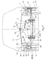
- la figure 2 est une vue en plan montrant une liaison au sol selon l'invention ;
- la figure 3 est une vue schématique de face, montrant une variation de carrossage ;
- la figure 4 est une vue en plan montrant un débattement de la suspension horizontale.
- Figure 1 is a schematic front view showing the main bodies of two ground connections located on a vehicle;
- Figure 2 is a plan view showing a ground connection according to the invention;
- Figure 3 is a schematic front view showing a variation in camber;
- Figure 4 is a plan view showing a movement of the horizontal suspension.
On voit en particulier à la figure 1 un châssis 1 constitué par une poutre centrale,
auquel tous les organes du véhicule sont accrochés. De préférence, chaque liaison au
sol du véhicule est identique. Quatre roues 2 sont donc montées sur le châssis 1 par
des organes identiques, ce qui fait qu'il suffit de décrire une seule des liaisons au sol
pour une description complète de l'invention. On voit que sur chaque roue 2 est monté
un pneumatique 20 dont le profil en coupe radiale rappelle celui des pneus pour
motos, du fait que le pneumatique doit fonctionner à des angles de carrossage très
éloignés de zéro degré. La roue 2 est montée sur un porte-roue 3 (on appelle "porte-roue
" l'organe non tournant) par l'intermédiaire d'un moyeu 21 et d'un roulement 22,
schématisés à la partie droite de la figure 1.We see in particular in Figure 1 a
Le porte-roue 3 suit fidèlement tous les mouvements de la roue 2 (sauf bien entendu la
rotation de la roue autour de son axe de rotation). Le porte-roue 3 est monté sur un
support 5, le débattement voulu pour la suspension verticale intervenant entre le
support 5 et le porte-roue 3. Le porte-roue 3 est monté sur le support 5 par
l'intermédiaire d'un barreau 30 unique coulissant dans le support 5 et guidé par celui-ci.
Le porte-roue est immobilisé sur le barreau 30 aux deux extrémités de celui-ci. Le
barreau 30 est disposé dans le volume délimité radialement par la jante de ladite roue
2. Le débattement de suspension d'une roue intervient dans ce cas parallèlement au
plan de roue. On peut contrôler le débattement de la roue par exemple par un ressort
hélicoïdal 81 (voir figure 2) et par un amortisseur qui peut être monté à l'intérieur du
ressort (non représenté pour ne pas surcharger le dessin). Une autre solution sera
abordée avec plus de précisions dans la suite.The
Les points de montage du support 5 sur le véhicule sont au nombre de trois : un point
supérieur A3 à l'extrémité d'une patte 59, ainsi que deux points inférieurs A1, A2
formant un axe géométrique de carrossage AA (visible notamment à la partie gauche
de la figure 1, où certains autres organes ne sont pas représentés pour bien faire
apparaítre le montage du support 5). Le support 5 peut ainsi être rigoureusement
maintenu en position (maintien du plan de roue) par ces trois points. Le support 5 est
relié au châssis 1 du véhicule par un bras de report de charge 70 monté aux deux
points inférieurs A1 et A2, et par une biellette de carrossage 71. Il subsiste ainsi un
degré de liberté de basculement du support 5 autour de l'axe géométrique de
carrossage AA. Sous l'action de moyens de commande du carrossage, on déplace la
biellette de carrossage 71 transversalement par rapport au châssis 1 pour faire varier la
position du point A3 par rapport à la position de l'axe géométrique de carrossage AA,
ce qui permet de changer la valeur du carrossage de la roue 2.There are three mounting points for the
Le braquage éventuel de la roue 2 est autorisé par un pivot 50 de préférence intégré au
support 5. A cet effet et dans ce mode particulier de réalisation, le support 5 comporte
un premier élément 51 de guidage de la roue 2 et un deuxième élément 52 de montage
sur lequel sont aménagés lesdits trois points A1, A2 et A3 de montage du support 5
sur le véhicule. Le barreau 30 coulisse dans le premier élément 51, ce qui procure le
mouvement de suspension verticale, mais ne peut tourner autour de son axe
géométrique indépendamment du premier élément 51. Le premier élément 51 est
monté dans le deuxième élément 52 par roulements 53 centrés sur l'axe du barreau 30,
aucune translation parallèle à l'axe géométrique du barreau 30 du premier élément 51
par rapport au deuxième élément 52 n'étant possible. Les premier élément 51 et
deuxième élément 52 forment ainsi un pivot 50. La patte 59 dont il a été question ci-dessus
prolonge le premier élément 51 et se termine en le point A3 de commande du
carrossage de la roue 2. Un levier 58 prolonge le deuxième élément 52 et se termine en
un point A4 de commande du braquage de la roue 2. L'angle de braquage est contrôlé
par une biellette de braquage 75, visible notamment à la figure 2 et à la partie droite de
la figure 1.The possible deflection of the
Les extrémités (côté actionneur pour commander le carrossage) des biellettes de
carrossage 71 des roues d'un même essieu (c'est à dire des roues 2 situées de part et
d'autre du châssis 1 et en regard l'une de l'autre) se rejoignent sensiblement au centre
du véhicule où chacune est montée en un point A5 sur une même platine 72. La platine
72 est disposée à l'extrémité d'un levier central 74 articulé sur le châssis 1 en un point
situé sur un axe de roulis 90, sur lequel on reviendra dans la suite de la description. Le
déplacement transversal de la platine 72 par rapport au châssis 1 est commandé par un
vérin de carrossage 73, irréversible ou freiné, dont la longueur est pilotée de façon
appropriée. Bien entendu, de par la commande centrale, les roues 2 s'inclinent du
même côté, c'est à dire de façon non symétrique par rapport au châssis.The ends (actuator side to control the camber) of the connecting
En consultant les figures 1 et 3, on aperçoit bien les quatre points déterminant les
caractéristiques géométriques de la commande de l'angle de carrossage des roues 2, à
savoir le point situant l'axe géométrique de carrossage AA, le point situant l'axe de
roulis 90, et les points A3 et A5. Dans cette réalisation, ces quatre points forment une
figure qui s'approche d'un parallélogramme. De part l'imperfection du
parallélogramme, les angles de carrossages qui en résultent sont différents à gauche et
à droite. Pour un angle de valeur p imposé au levier central 74 par le vérin de
carrossage 73, l'angle de carrossage γE du côté extérieur au virage est de valeur
supérieure à la valeur ρ et l'angle de carrossage γI du côté intérieur au virage est de
valeur inférieure à la valeur ρ. De ce fait, la voie au sol du véhicule est sensiblement
élargie, ce qui est favorable à la stabilité. En outre, compte tenu que les charges
reportées sur les roues en virage sont elles-mêmes très dissymétriques, les roues
extérieures au virage étant surchargées, une telle commande de carrossage simplifiée
apporte toutes satisfactions.By consulting FIGS. 1 and 3, we can clearly see the four points determining the geometric characteristics of the control of the camber angle of the
On voit notamment aux figures 1 et 4 que le bras de report de charge 70 est, du côté du
châssis 1, est monté suivant un axe géométrique sensiblement vertical AK. On voit
deux points d'accrochage superposés AK1 et AK2, et écartés l'un de l'autre. Le bras
de report de charge 70 ne peut pas tourner dans le plan vertical (figures 1 et 3). Dès
lors, la charge supportée par le châssis 1 est entièrement reportée sur l'ensemble des
bras de report de charge 70. Dans le plan horizontal (figures 2 et 4), il faut reprendre le
moment autour de l'axe géométrique sensiblement vertical AK dû aux sollicitations
horizontales venant des efforts moteurs et/ou freineurs et/ou des chocs exercés sur la
roue. Le bras de report de la charge 70 doit de préférence prendre appui sur le châssis
1 en un point distant de l'axe géométrique sensiblement vertical AK. Un élément
formant triangulation 6 est à cette fin monté d'une part sur le bras de report de charge
70 à un point intermédiaire 61 entre ses extrémités, et d'autre part sur le châssis à un
point distant 62 de l'axe géométrique sensiblement vertical AK du bras de report de
charge 70.It can be seen in particular in FIGS. 1 and 4 that the
L'invention se prête avantageusement à l'implantation d'une suspension horizontale.
On peut par exemple monter le bras de report de charge 70 aux points d'accrochage
superposés AK1 et AK2 de façon à ce qu'il puisse tourner assez librement autour
dudit axe géométrique sensiblement vertical AK, ce qui procure une certaine latitude
de mouvement longitudinal au support 5, donc à la roue 2. Et on utilise l'élément
formant triangulation 6 pour contrôler le débattement de suspension horizontale du
bras de report de charge 70. L'élément formant triangulation 6 est un élément jouissant
d'une certaine élasticité, autorisant (mais en le contrôlant) un mouvement d'oscillation
du bras de report de charge 70 autour de l'axe géométrique sensiblement vertical AK.
Il comporte un moyen procurant une fonction de ressort et un moyen procurant une
fonction d'amortissement. Un élément en caoutchouc correctement formulé peut,
comme on le sait, procurer ces deux fonctions.The invention advantageously lends itself to the implantation of a horizontal suspension.
We can for example mount the
Le mécanisme de carrossage simplifié proposé peut s'accommoder des mouvements de la suspension horizontale, tout en n'introduisant que des variations de carrossage imperceptibles.The proposed simplified camber mechanism can accommodate movements of the horizontal suspension, while introducing only camber variations imperceptible.
Explicitons maintenant la commande du braquage. On voit à la figure 2 que, vue dans
un plan horizontal, la biellette de braquage 75 forme un trapèze avec le bras de report
de charge 70. La longueur de la biellette de braquage 75 est plus grande que la
longueur du bras de report de charge 70. Par ailleurs, la biellette de braquage 75 est
actionnée par un levier 76 de commande de direction monté articulé sur l'axe
géométrique sensiblement vertical AK du bras de report de charge 70. L'extrémité 77
du levier 76 aboutit dans le plan longitudinal π contenant l'axe géométrique
sensiblement vertical AK. La commande de braquage d'une butée de direction à
l'autre, par une barre de direction 78, fait décrire à l'extrémité 77 du levier 76 un
mouvement symétrique par rapport audit plan longitudinal π. C'est par cette
disposition que l'on réalise une commande selon le principe de l'épure de Jeantaud.Let us now explain the steering control. We see in Figure 2 that, seen in
a horizontal plane, the turning
Soulignons que l'adoption d'une liaison au sol offrant un carrossage variable sur une
grande plage de réglage se marie tout particulièrement bien avec l'utilisation d'une
traction par moteurs électriques implantés dans les roues. Il convient donc que les
organes mécaniques laisse la place nécessaire à ces moteurs de traction. La mise en
oeuvre préférée illustrant l'invention adopte aussi l'implantation d'un moteur
électrique de traction 80 déjà décrite dans la demande de brevet EP 0 878 332. Le
contrôle du mouvement de suspension verticale peut aussi adopter l'implantation
proposée dans la même demande de brevet EP 0 878 332. C'est ce qui est montré aux
dessins. Il existe une crémaillère (usinée sur le barreau 30) dont le mouvement est
contrôlé par un moteur électrique de suspension 82. Le moteur électrique de
suspension 82 reste immobile verticalement quelle que soit la déflexion de la
suspension verticale, et il suit les mouvements du plan de roue en braquage et en
carrossage.Note that the adoption of a ground connection offering variable camber on a
large adjustment range goes particularly well with the use of a
traction by electric motors installed in the wheels. Therefore, the
mechanical parts leaves room for these traction motors. Setting
preferred work illustrating the invention also adopts the implantation of a
A la figure 2, on a représenté (en traits interrompus) la position du moteur de traction
80 roue braquée en butée à droite. C'est la position vers laquelle pointe la référence
« 80 ». On voit que le bras de report de charge 70 est courbé de façon à dégager
l'espace nécessaire, compte tenu du fait que ce moteur de traction 80 accompagne les
mouvements du plan de roue en braquage et les mouvements de débattement verticaux
de la roue. A la figure 3, on a représenté pour chacune des roues 2 la position du
moteur de suspension 82 lorsque les roues 2 sont en butée de carrossage. On voit aux
figures 2 et 4 que le bras de report de charge 70 est formé de façon à dégager l'espace
nécessaire, compte tenu du fait que ce moteur de traction 80 accompagne les
mouvements du plan de la roue en braquage, en carrossage et en débattement. On voit
aux figures 1 et 3 que le bras de report de charge 70 et la patte 59 sont formés de façon
à dégager l'espace nécessaire, compte tenu du fait que ce moteur de suspension 82
accompagne les mouvements du plan de la roue en braquage et en carrossage. In FIG. 2, the position of the traction motor is shown (in dashed lines).
80 wheel turned to the stop on the right. This is the position to which the reference points
"80". We see that the
De préférence, le mécanisme de direction doit rendre l'angle de braquage des roues suffisamment insensible aux variations de carrossage et aux mouvements de suspension horizontale (voire aux variations de roulis de la caisse si celui-ci est contrôlé activement, comme proposé ci-dessous).Preferably, the steering mechanism must make the steering angle of the wheels sufficiently insensitive to camber variations and movement of horizontal suspension (see variations in body roll if this is actively controlled, as proposed below).
Sur un essieu non directeur, on peut utiliser une liaison au sol simplifiée, ne
permettant pas le braquage de la roue. Par exemple, le support 5 est monobloc et
l'élément formant triangulation 6 est alors de préférence rigide. Le plan de roue est
tenu en braquage par le fait que les points A1 et A2 définissant l'axe géométrique de
carrossage AA sont suffisamment écartés l'un de l'autre et sont reliés à la même pièce
mécanique, à savoir bras de report de charge 70.On a non-steered axle, you can use a simplified ground link, do not
not allowing the wheel to turn. For example, the
Sur un essieu non directeur, on peut aussi utiliser un support 5 en deux éléments 51 et
52 comme décrit ci-dessus et on immobilise le porte-roue en connectant de façon
appropriée une biellette au levier 58 du premier élément 51 d'une part et au châssis 1
d'autre part. Si le support 5 recule par rapport au châssis 1, le deuxième élément 52
subit une légère rotation, qui est automatiquement compensée par un léger braquage
du premier élément 51 dans le deuxième élément 52. On évite ainsi qu'apparaisse un
braquage induit par le déplacement du support le long de la course de suspension
horizontale.On a non-steered axle, one can also use a
Quant à l'habitacle du véhicule, soit il est solidaire du châssis 1, soit il est monté sur le châssis 1 comme l'habitacle 9 du véhicule illustrant l'invention. L'axe de roulis 90, dont il a été question ci-dessus, est un axe longitudinal sensiblement horizontal. Dans ce dernier cas, le véhicule est tel qu'il comporte :
un habitacle 9 pour le transport de passagers, montée sur le châssis 1 de façon inclinable autour d'un axe de roulis 90 sensiblement longitudinal, de sorte que l'habitacle forme parrapport audit châssis 1 un angle de roulis variable,- des moyens de contrôle du roulis interposés entre le châssis 1 et l'habitacle, agissant de façon à imposer ledit angle de roulis, dans le même sens que le carrossage imposé aux roues.
- a
passenger compartment 9 for the transport of passengers, mounted on thechassis 1 in a tiltable manner around a substantiallylongitudinal roll axis 90, so that the passenger compartment forms with respect to said chassis 1 a variable roll angle, - roll control means interposed between the
chassis 1 and the passenger compartment, acting so as to impose said roll angle, in the same direction as the camber imposed on the wheels.
De préférence, les moyens de contrôle du roulis sont constitués essentiellement par le
vérin de carrossage 73, de sorte que la variation de carrossage des roues 2 et la
variation de l'angle de roulis de l'habitacle sont synchrones.Preferably, the roll control means consist essentially of the
En rendant l'habitacle solidaire du levier de carrossage 74, l'habitacle prend un angle
de roulis p dans le sens inverse du sens habituel pour les véhicules de tourisme. Cela
contribue au confort des passagers, y compris par une perception de plus grande
sécurité. Notons que cela contribue aussi en soi à la sécurité, en déplaçant le centre de
gravité du véhicule vers l'intérieur du virage, ce qui diminue la part de charge
transférée sur les roues extérieures au virage. Non seulement les pneus travaillent dans
une position par rapport au sol plus favorable, mais en outre, dans ce mode de
réalisation, la surcharge momentanée des pneus du côté extérieur au virage est
moindre que s'il n'y avait pas de correction de carrossage. Les pneus du côté intérieur
sont moins délestés, et donc leur aptitude à développer des poussées de dérive est
mieux préservée.By making the cabin integral with the
Afin de piloter l'angle de carrossage, voire de roulis de l'habitacle, en fonction de la force centrifuge qui s'exerce sur le véhicule, on peut installer sur le véhicule au moins un capteur pour relever la valeur d'au moins un paramètre permettant une évaluation de l'accélération transversale s'exerçant sur le véhicule, des moyens de calcul pour calculer l'amplitude de l'angle de carrossage en fonction de la ou des valeurs relevées. L'angle de carrossage peut être piloté individuellement roue par roue, ou collectivement pour toutes les roues ou pour les roues d'un même essieu.In order to control the camber angle, or even the roll angle of the passenger compartment, depending on the centrifugal force exerted on the vehicle, at least one can install on the vehicle a sensor for reading the value of at least one parameter allowing an evaluation transverse acceleration acting on the vehicle, calculation means for calculate the amplitude of the camber angle as a function of the value or values recorded. The camber angle can be controlled individually wheel by wheel, or collectively for all wheels or for wheels on the same axle.
Il peut s'agir d'une mesure directe de l'accélération centrifuge, ou bien d'une évaluation en fonction de paramètres indirects que sont la vitesse du véhicule et l'angle au volant. Dans tous les cas, des moyens de calcul (par exemple un microprocesseur chargé du programme adéquat) permettent de mettre en oeuvre des stratégies de régulations à l'image de ce que l'on fait pour piloter des suspensions actives, afin de calculer l'angle de roulis à imposer. Une telle stratégie peut tenir compte de diverses lois de commande, comme par exemple une valeur de proportionnalité fixant le niveau d'accélération transversale auquel on atteint l'angle de roulis maximal permis par le mécanisme de roulis.It can be a direct measurement of centrifugal acceleration, or a evaluation based on indirect parameters such as vehicle speed and the steering wheel angle. In all cases, means of calculation (for example a microprocessor responsible for the appropriate program) allow the implementation of regulation strategies like what we do to control suspensions active, in order to calculate the roll angle to be imposed. Such a strategy can hold account for various control laws, such as for example a value of proportionality setting the level of transverse acceleration at which the angle is reached maximum roll allowed by the roll mechanism.
Sur la base de ce qui vient d'être exposé, l'homme du métier pourra procéder à des adaptations selon ses propres souhaits sans sortir du cadre de la présente invention. Par exemple, rien n'empêche d'ajouter un filtrage entre l'habitacle et le châssis, par exemple par des cales élastiques en caoutchouc. On pourrait bien entendu construire le pivot différemment. L'axe de pivot pourrait ne pas être dans le plan de roue, ou tout en étant dans le plan de la roue, il pourrait être incliné (pour procurer un angle de chasse non nul), selon de nombres variantes constructives.On the basis of what has just been explained, the person skilled in the art can carry out adaptations according to his own wishes without departing from the scope of the present invention. Through example, nothing prevents adding filtering between the passenger compartment and the chassis, by example by elastic rubber shims. We could of course build the pivot differently. The pivot axis may not be in the wheel plane, or all while being in the plane of the wheel, it could be tilted (to provide a hunting angle not zero), according to constructive variant numbers.
L'invention s'applique notamment aux véhicules à quatre roues comme les voitures de tourisme. Or la variation d'angle de carrossage dont il est ici question est de grande ampleur, c'est à dire plus proche des valeurs couramment balayées par les motos que des valeurs de réglage pouvant exister dans un véhicule de tourisme classique, à quatre roues. Pour fixer les idées, la plage de variation est de l'ordre de ± 15° à ± 20°. La plage de variation est en tout cas telle que, lorsque la roue bascule autour de son aire de contact avec le sol, le déplacement dans le sens transversal de la partie radialement supérieure de la roue peut atteindre une ampleur supérieure à la largeur de ladite roue.The invention applies in particular to four-wheeled vehicles such as passenger cars tourism. The variation in camber angle in question here is large magnitude, i.e. closer to the values commonly scanned by motorcycles than adjustment values which may exist in a conventional passenger vehicle, four wheels. To fix ideas, the range of variation is of the order of ± 15 ° to ± 20 °. The variation range is in any case such that, when the wheel rocks around its area contact with the ground, the transverse displacement of the part radially upper wheel can reach a magnitude greater than the width of said wheel.
Claims (10)
- Vehicle comprising:characterised in thata rolling and suspended chassis (1),at least two ground contact systems each comprising a wheel (2), the said ground contact systems being mounted on the said chassis (1) transversely on either side thereof, the wheel (2) of each ground contact system being mounted on a stub axle (3), the stub axle (3) being mounted on a support (5) by a vertical suspension device that permits vertical deflection of the stub axle (3) relative to the support (5), the deflection movement taking place in the plane of the wheel (2), the deflection path being sufficient to permit the vertical suspension movement required, and the deflection path being controlled by appropriate means,the said support (5) being mounted on the said chassis (1) by a load transfer arm (70), at one side of which the support is articulated along an essentially horizontal geometrical camber axis (AA),each support (5) being mounted on the said chassis (1) in a manner that makes it possible to incline the plane of each wheel (2) relative to the said chassis in order to impose on the planes of the said wheels (2) a camber angle γ of the desired amplitude, by inclining the wheels (2) relative to the ground all on the same side,a camber control rod (71) being mounted articulated to the support (5) and some distance away from the geometrical camber axis (AA), the camber control rod (71) being able to move transversely relative to the chassis (1),the said load transfer arm is connected at its other side to the chassis along an essentially vertical geometrical axis (AK),a triangulation-forming element (6) connects the load transfer arm (70) to the chassis (1), such that it controls the torque moment about the essentially vertical geometrical axis (AK).
- Vehicle according to Claim 1,
characterised in that
the support (5) comprises a first element (51) that steers the wheel (2) and a second element (52) on which the load transfer arm (70) is mounted, the first and second elements (51) and (52) together forming a pivot (50) that defines a geometrical pivot axis which enables the wheel (2) to be steered relative to the chassis (1), the steering angle being controlled by a track rod (75). - Vehicle according to Claim 2 in which, viewed in a horizontal plane, the track rod (75) forms a trapezium with the load transfer arm (70).
- Vehicle according to Claims 2 or 3, in which the track rod (75) is actuated by a direction control lever (76) mounted articulated to the essentially vertical geometrical axis (AK) of the load transfer arm (70).
- Vehicle according to any of Claims 1 to 4, in which the triangulation-forming element (6) which controls the horizontal suspension deflection of the load transfer arm is mounted on the one hand on the load transfer arm (70) at a point (61) intermediate between its ends, and on the other hand on the chassis at a point (62) some distance away from the essentially vertical geometrical axis (AK) of the load transfer arm (70).
- Vehicle according to any of Claims 1 to 5, in which the triangulation-forming element (6) is an element that permits an oscillation movement of the load transfer arm (70) about the essentially vertical geometrical axis (AK), such that a horizontal suspension is procured.
- Vehicle according to any of Claims 1 to 6, in which the control-side ends of the camber control rods (71) are essentially united at the centre of the vehicle, where each is mounted on the same plate (72), whose transverse movement relative to the chassis (1) is controlled by a camber control jack (73).
- Vehicle according to any of Claims 1 to 7, comprising:a passenger compartment (9) for the transport of passengers, mounted on the chassis (1) and able to tilt about an essentially longitudinal roll axis (90), such that the passenger compartment can move through a variable roll angle relative to the said chassis (1),means for controlling the roll interposed between the chassis (1) and the passenger compartment, which act so as to impose the said roll angle in the same direction as the camber imposed on the wheels.
- Vehicle according to Claims 7 and 8, in which the roll control means consist essentially of the camber control jack (73), such that the camber variation of the wheels (2) and the variation of the roll angle of the passenger compartment are synchronous.
- Vehicle according to any of Claims 1 to 9, comprising at least one sensor to detect the value of at least one parameter that enables evaluation of the transverse acceleration acting on the vehicle, and computation means for calculating the amplitude of the camber angle as a function of the value(s) determined.
Applications Claiming Priority (3)
| Application Number | Priority Date | Filing Date | Title |
|---|---|---|---|
| FR0004596A FR2807378A1 (en) | 2000-04-10 | 2000-04-10 | VEHICLE COMPRISING A SUSPENSION TO A BODY VARIATION AND VERTICAL SUSPENSION IN THE WHEELPLANE |
| FR0004596 | 2000-04-10 | ||
| US09/922,155 US6511087B1 (en) | 2001-08-06 | 2001-08-06 | Jogging kick scooter |
Publications (2)
| Publication Number | Publication Date |
|---|---|
| EP1145879A1 EP1145879A1 (en) | 2001-10-17 |
| EP1145879B1 true EP1145879B1 (en) | 2004-01-21 |
Family
ID=26212336
Family Applications (1)
| Application Number | Title | Priority Date | Filing Date |
|---|---|---|---|
| EP01107977A Expired - Lifetime EP1145879B1 (en) | 2000-04-10 | 2001-03-29 | Vehicle comprising a vertical, in-wheel suspension with variable camber |
Country Status (4)
| Country | Link |
|---|---|
| US (1) | US6511078B2 (en) |
| EP (1) | EP1145879B1 (en) |
| JP (1) | JP2002052915A (en) |
| FR (1) | FR2807378A1 (en) |
Families Citing this family (45)
| Publication number | Priority date | Publication date | Assignee | Title |
|---|---|---|---|---|
| US6398251B1 (en) * | 1997-01-31 | 2002-06-04 | Dallas Smith Corporation | Axleless vehicle suspension system |
| US6967484B2 (en) * | 2000-03-27 | 2005-11-22 | Midtronics, Inc. | Electronic battery tester with automotive scan tool communication |
| DE60224010T2 (en) * | 2001-01-23 | 2008-12-04 | Société de Technologie Michelin | HANGING DEVICE FOR A MOTORCYCLE WHEEL |
| DE10120918B4 (en) * | 2001-04-27 | 2011-05-05 | Continental Aktiengesellschaft | Electrically adjustable, semi-active damper control |
| WO2003057529A2 (en) * | 2002-01-08 | 2003-07-17 | Hypercar, Inc. | Advanced composite hybrid-electric vehicle |
| KR20040006288A (en) * | 2002-07-11 | 2004-01-24 | 현대자동차주식회사 | rear suspention system of minicar |
| US7246806B2 (en) * | 2002-07-22 | 2007-07-24 | Michelin Recherche Et Technique S.A. | Suspension system for a vehicle wheel |
| DE10304916A1 (en) * | 2003-02-07 | 2004-08-26 | O&K Orenstein & Koppel Ag | Method and device for camber adjustment |
| US20050017471A1 (en) * | 2003-06-09 | 2005-01-27 | Matthew Kim | Steering with triple linkage suspension having steering adjusted camber |
| WO2005000606A1 (en) * | 2003-06-30 | 2005-01-06 | Bridgestone Corporation | Suspension |
| ITTO20030639A1 (en) * | 2003-08-14 | 2005-02-15 | Marco Martina | STABILIZATION DEVICE FOR VEHICLES. |
| FR2858964B1 (en) * | 2003-08-18 | 2005-10-07 | Michelin Soc Tech | SUSPENSION DEVICE FOR VARIATION OF BODY AND VEHICLE COMPRISING SAID DEVICE |
| JP4813360B2 (en) * | 2003-08-18 | 2011-11-09 | ソシエテ ド テクノロジー ミシュラン | Suspension device |
| WO2005039900A2 (en) * | 2003-10-24 | 2005-05-06 | Aloha, Llc | Suspensions for low floor vehicles |
| FR2872773B1 (en) * | 2004-07-07 | 2006-09-29 | Moulene Sarl | MOTORIZED VEHICLE OF LOW WIDTH |
| FR2873061B1 (en) * | 2004-07-15 | 2008-12-05 | Conception & Dev Michelin Sa | VEHICLE COMPRISING A GROUND CONNECTION PROVIDING THE INDIVIDUAL SUSPENSION OF THE WHEELS, AND AN ACTIVE CONTROL OF THE HEIGHT OF THE BODY |
| US7625000B2 (en) * | 2004-12-06 | 2009-12-01 | Zarach Industries, Inc. | Variable ratio floating suspension system |
| JP4534944B2 (en) * | 2005-10-07 | 2010-09-01 | トヨタ自動車株式会社 | vehicle |
| US7845666B2 (en) * | 2006-03-06 | 2010-12-07 | Purdue Research Foundation | Swinging hub for adjusting wheel camber |
| US20070267883A1 (en) * | 2006-05-19 | 2007-11-22 | Gravititech Llc | Titling Vehicle Frame |
| US7914020B2 (en) * | 2008-01-31 | 2011-03-29 | Roy Boston | Vehicle suspension system with a variable camber system |
| US8818700B2 (en) | 2008-02-29 | 2014-08-26 | Daniel Moulene | Motorised vehicle with controlled inclination |
| FR2928130B1 (en) * | 2008-02-29 | 2010-05-28 | Moulene | MOTORIZED VEHICLE WITH CONTROLLED INCLINATION. |
| WO2009126787A2 (en) * | 2008-04-10 | 2009-10-15 | Sacli Suspension, Llc | Suspension system providing two degrees of freedom |
| KR100986088B1 (en) * | 2008-11-11 | 2010-10-07 | 현대자동차주식회사 | Active geometry controlled suspension |
| KR101028058B1 (en) | 2009-04-06 | 2011-04-08 | 현대로템 주식회사 | Self-alignment suspension for multi-axis in-wheel motor vehicle |
| US20100320023A1 (en) * | 2009-06-23 | 2010-12-23 | Michael Rhodig | Four wheel vehicle having a rotatable body section and method therefor |
| CA2714255A1 (en) | 2009-09-01 | 2011-03-01 | Timbren Industries Inc. | Suspension mechanism |
| DK177094B1 (en) * | 2009-09-15 | 2011-08-22 | Ecomove Aps | A transport means and a vehicle |
| US8641064B2 (en) | 2011-12-29 | 2014-02-04 | Garbis Krajekian | Tilting vehicle with a non-tilting automobile-like body |
| DE102014201127B4 (en) | 2013-03-07 | 2022-02-03 | Ford Global Technologies, Llc | Side-tilting, multi-track vehicle |
| DE102014201668B4 (en) | 2013-03-07 | 2021-09-02 | Ford Global Technologies, Llc | Laterally tiltable, multi-lane vehicle |
| DE102014201632B4 (en) | 2013-03-07 | 2021-09-02 | Ford Global Technologies, Llc | Laterally tiltable, multi-lane vehicle |
| DE102014201670A1 (en) | 2013-03-07 | 2014-09-11 | Ford Global Technologies, Llc | Sideways inclinable, multi-lane vehicle |
| DE102014201630B4 (en) | 2013-03-07 | 2021-09-02 | Ford Global Technologies, Llc | Laterally tiltable, multi-lane vehicle |
| RU2607691C1 (en) * | 2014-05-13 | 2017-01-10 | Текнолоджи Инвестментс Лимитед | Steering control system |
| DE102014217246B3 (en) | 2014-08-29 | 2015-12-24 | Ford Global Technologies, Llc | Stabilization arrangement for a tilting chassis of a vehicle |
| DE102014217386A1 (en) | 2014-09-01 | 2016-03-03 | Ford Global Technologies, Llc | Method for operating a tilting chassis and active tilting suspension for a rail-bound vehicle |
| US10076939B2 (en) | 2014-11-26 | 2018-09-18 | Ford Global Technologies, Llc | Suspension systems for laterally tiltable multitrack vehicles |
| US9925843B2 (en) | 2015-02-24 | 2018-03-27 | Ford Global Technologies, Llc | Rear suspension systems for laterally tiltable multitrack vehicles |
| US10023019B2 (en) | 2015-02-24 | 2018-07-17 | Ford Global Technologies, Llc | Rear suspension systems with rotary devices for laterally tiltable multitrack vehicles |
| DE102015203632A1 (en) * | 2015-03-02 | 2016-09-08 | Zf Friedrichshafen Ag | Independent suspension with high steering angle |
| KR101614701B1 (en) * | 2015-08-05 | 2016-04-25 | 자동차부품연구원 | Tilting apparatus for vehicle |
| US10639952B2 (en) * | 2017-12-01 | 2020-05-05 | Mahindra N.A. Tech Center | Vehicle suspension |
| CN110126571B (en) * | 2019-05-28 | 2021-06-08 | 西南交通大学 | Anti-rollover device for hub motor tire |
Family Cites Families (13)
| Publication number | Priority date | Publication date | Assignee | Title |
|---|---|---|---|---|
| US2152938A (en) * | 1936-07-11 | 1939-04-04 | Edward L Welch | Vehicle banking mechanism |
| FR967710A (en) * | 1948-06-11 | 1950-11-10 | Method for combating centrifugal force, in bends, on a vehicle with three or four wheels; and oscillating frame with center of gravity movable during turns | |
| DE1214100B (en) * | 1956-12-18 | 1966-04-07 | Armin Drechsel | Axle or wheel guide arrangement for vehicles, especially motor vehicles, with the vehicle body sloping towards the inside of the curve |
| US3485506A (en) * | 1967-03-06 | 1969-12-23 | John J Melbar | Vehicle steering apparatus |
| US4159128A (en) * | 1977-11-18 | 1979-06-26 | Ferol B. Blaine | Vehicle suspension system including wheel-tilting mechanism |
| DE2822058A1 (en) * | 1978-05-20 | 1979-11-29 | Porsche Ag | WHEEL SUSPENSION OF A MOTOR VEHICLE |
| US4487429A (en) * | 1982-09-30 | 1984-12-11 | Ruggles Thomas P | Tilting wheel vehicle suspension system |
| US4700972A (en) * | 1985-06-20 | 1987-10-20 | Young Colin G | Computerized, central hydraulic, electronic variable suspension |
| WO1987002951A1 (en) * | 1985-11-15 | 1987-05-21 | Phillip Ronald James | Self stabilizing cambering vehicle |
| JPS63101114A (en) * | 1986-10-15 | 1988-05-06 | Honda Motor Co Ltd | Suspension structure for automobile |
| US4796720A (en) * | 1987-09-21 | 1989-01-10 | Bauer John K | Four-wheel steering, leveling and banking for vehicles |
| FR2763300A1 (en) | 1997-05-16 | 1998-11-20 | Conception & Dev Michelin Sa | VEHICLE HAVING A SUSPENSION HAVING AN ACTIVE BODY VARIATION |
| FR2763284A1 (en) | 1997-05-16 | 1998-11-20 | Conception & Dev Michelin Sa | PACKAGE INCLUDING A WHEEL AND INTEGRATED WHEEL SUSPENSION |
-
2000
- 2000-04-10 FR FR0004596A patent/FR2807378A1/en active Pending
-
2001
- 2001-03-29 EP EP01107977A patent/EP1145879B1/en not_active Expired - Lifetime
- 2001-04-09 US US09/829,058 patent/US6511078B2/en not_active Expired - Lifetime
- 2001-04-10 JP JP2001111443A patent/JP2002052915A/en active Pending
Also Published As
| Publication number | Publication date |
|---|---|
| US6511078B2 (en) | 2003-01-28 |
| EP1145879A1 (en) | 2001-10-17 |
| JP2002052915A (en) | 2002-02-19 |
| US20010028154A1 (en) | 2001-10-11 |
| FR2807378A1 (en) | 2001-10-12 |
Similar Documents
| Publication | Publication Date | Title |
|---|---|---|
| EP1145879B1 (en) | Vehicle comprising a vertical, in-wheel suspension with variable camber | |
| EP1125828B1 (en) | Vehicle suspension with active camber variation | |
| EP1247663B1 (en) | Vehicle suspension with camber variation | |
| EP1070609B1 (en) | Motor vehicle equipped with a system controlling wheel camber during cornering | |
| EP1276656B1 (en) | Wheel supporting device and suspension device comprising same | |
| EP1363795B1 (en) | Suspension device of a motor vehicle wheel | |
| EP1616731B1 (en) | Vehicle with link to the ground enabling independent wheel suspension and active control of the chassis height | |
| EP1765615B1 (en) | Motor vehicle suspension device | |
| WO2006129020A1 (en) | Pendulum compartment road vehicle | |
| EP1578626A1 (en) | Wheel support device with three pivots, suspension device and vehicle comprising said support device | |
| WO2007036547A1 (en) | Vehicle suspension device | |
| WO2004009383A1 (en) | Vehicle wheel suspension device | |
| FR2833233A1 (en) | Vehicle wheel suspension comprises wheel support articulated to suspension elements enabling variation of camber angle independent of suspension clearance | |
| EP1572475B1 (en) | Wheel support device, suspension device and vehicle comprising one such support device | |
| WO2005021294A1 (en) | Suspension device | |
| CA2021553C (en) | Motorcycle side-car frame | |
| FR2675431A1 (en) | Vehicle suspension device with articulated strut | |
| EP1996415B1 (en) | Vehicle with a variable-camber suspension device | |
| EP4339084A1 (en) | Tricycle vehicle | |
| FR2752213A1 (en) | IMPROVEMENT FOR VEHICLE CHASSIS | |
| FR2878495A1 (en) | Front end for e.g. motorcycle, has oscillating arm in two parts, with front ends connected to lower ends of plates and rear ends connected to frame, and brake calipers fixed on plates to follow movement of plates during directional control | |
| FR2999143A1 (en) | Vehicle e.g. motor cycle, has mechanical connection, connection arm and element provided between upper part of variable length arm and chassis to adjust slope of variable length arm in vertical symmetry plane of steering gear | |
| FR2823149A1 (en) | Suspension system comprises support bar mounted on chassis by ball and socket joints at and connected to wheel mounting by two more ball and socket joints, producing desired degree of camber for wheels | |
| FR2819753A1 (en) | Vehicle wheel suspension system has wheel carrier camber movement allowing given distance for instantaneous center of rotation | |
| FR2916683A1 (en) | Drive axle suspending mechanism for motor vehicle, has modifying unit modifying camber angle of wheels during turning of vehicle, drive axle maintained by suspension spring, and connecting rods connecting drive axle with steering stub axle |
Legal Events
| Date | Code | Title | Description |
|---|---|---|---|
| PUAI | Public reference made under article 153(3) epc to a published international application that has entered the european phase |
Free format text: ORIGINAL CODE: 0009012 |
|
| AK | Designated contracting states |
Kind code of ref document: A1 Designated state(s): AT BE CH CY DE DK ES FI FR GB GR IE IT LI LU MC NL PT SE TR |
|
| AX | Request for extension of the european patent |
Free format text: AL;LT;LV;MK;RO;SI |
|
| 17P | Request for examination filed |
Effective date: 20020417 |
|
| AKX | Designation fees paid |
Free format text: AT BE CH CY DE DK ES FI FR GB GR IE IT LI LU MC NL PT SE TR |
|
| GRAH | Despatch of communication of intention to grant a patent |
Free format text: ORIGINAL CODE: EPIDOS IGRA |
|
| GRAS | Grant fee paid |
Free format text: ORIGINAL CODE: EPIDOSNIGR3 |
|
| GRAA | (expected) grant |
Free format text: ORIGINAL CODE: 0009210 |
|
| AK | Designated contracting states |
Kind code of ref document: B1 Designated state(s): AT BE CH CY DE DK ES FI FR GB GR IE IT LI LU MC NL PT SE TR |
|
| PG25 | Lapsed in a contracting state [announced via postgrant information from national office to epo] |
Ref country code: IE Free format text: LAPSE BECAUSE OF FAILURE TO SUBMIT A TRANSLATION OF THE DESCRIPTION OR TO PAY THE FEE WITHIN THE PRESCRIBED TIME-LIMIT Effective date: 20040121 Ref country code: TR Free format text: LAPSE BECAUSE OF FAILURE TO SUBMIT A TRANSLATION OF THE DESCRIPTION OR TO PAY THE FEE WITHIN THE PRESCRIBED TIME-LIMIT Effective date: 20040121 Ref country code: FI Free format text: LAPSE BECAUSE OF FAILURE TO SUBMIT A TRANSLATION OF THE DESCRIPTION OR TO PAY THE FEE WITHIN THE PRESCRIBED TIME-LIMIT Effective date: 20040121 Ref country code: NL Free format text: LAPSE BECAUSE OF FAILURE TO SUBMIT A TRANSLATION OF THE DESCRIPTION OR TO PAY THE FEE WITHIN THE PRESCRIBED TIME-LIMIT Effective date: 20040121 Ref country code: ES Free format text: LAPSE BECAUSE OF FAILURE TO SUBMIT A TRANSLATION OF THE DESCRIPTION OR TO PAY THE FEE WITHIN THE PRESCRIBED TIME-LIMIT Effective date: 20040121 Ref country code: CY Free format text: LAPSE BECAUSE OF FAILURE TO SUBMIT A TRANSLATION OF THE DESCRIPTION OR TO PAY THE FEE WITHIN THE PRESCRIBED TIME-LIMIT Effective date: 20040121 Ref country code: AT Free format text: LAPSE BECAUSE OF FAILURE TO SUBMIT A TRANSLATION OF THE DESCRIPTION OR TO PAY THE FEE WITHIN THE PRESCRIBED TIME-LIMIT Effective date: 20040121 |
|
| REG | Reference to a national code |
Ref country code: GB Ref legal event code: FG4D Free format text: NOT ENGLISH |
|
| REG | Reference to a national code |
Ref country code: CH Ref legal event code: EP |
|
| REG | Reference to a national code |
Ref country code: IE Ref legal event code: FG4D Free format text: FRENCH |
|
| REF | Corresponds to: |
Ref document number: 60101809 Country of ref document: DE Date of ref document: 20040226 Kind code of ref document: P |
|
| PG25 | Lapsed in a contracting state [announced via postgrant information from national office to epo] |
Ref country code: LU Free format text: LAPSE BECAUSE OF NON-PAYMENT OF DUE FEES Effective date: 20040329 |
|
| PG25 | Lapsed in a contracting state [announced via postgrant information from national office to epo] |
Ref country code: MC Free format text: LAPSE BECAUSE OF NON-PAYMENT OF DUE FEES Effective date: 20040331 Ref country code: BE Free format text: LAPSE BECAUSE OF NON-PAYMENT OF DUE FEES Effective date: 20040331 |
|
| PG25 | Lapsed in a contracting state [announced via postgrant information from national office to epo] |
Ref country code: DK Free format text: LAPSE BECAUSE OF FAILURE TO SUBMIT A TRANSLATION OF THE DESCRIPTION OR TO PAY THE FEE WITHIN THE PRESCRIBED TIME-LIMIT Effective date: 20040421 Ref country code: SE Free format text: LAPSE BECAUSE OF FAILURE TO SUBMIT A TRANSLATION OF THE DESCRIPTION OR TO PAY THE FEE WITHIN THE PRESCRIBED TIME-LIMIT Effective date: 20040421 Ref country code: GR Free format text: LAPSE BECAUSE OF FAILURE TO SUBMIT A TRANSLATION OF THE DESCRIPTION OR TO PAY THE FEE WITHIN THE PRESCRIBED TIME-LIMIT Effective date: 20040421 |
|
| GBT | Gb: translation of ep patent filed (gb section 77(6)(a)/1977) |
Effective date: 20040422 |
|
| NLV1 | Nl: lapsed or annulled due to failure to fulfill the requirements of art. 29p and 29m of the patents act | ||
| REG | Reference to a national code |
Ref country code: IE Ref legal event code: FD4D |
|
| BERE | Be: lapsed |
Owner name: CONCEPTION ET DEVELOPPEMENT MICHELIN S.A. Effective date: 20040331 |
|
| PLBE | No opposition filed within time limit |
Free format text: ORIGINAL CODE: 0009261 |
|
| STAA | Information on the status of an ep patent application or granted ep patent |
Free format text: STATUS: NO OPPOSITION FILED WITHIN TIME LIMIT |
|
| 26N | No opposition filed |
Effective date: 20041022 |
|
| REG | Reference to a national code |
Ref country code: FR Ref legal event code: TP |
|
| PG25 | Lapsed in a contracting state [announced via postgrant information from national office to epo] |
Ref country code: PT Free format text: LAPSE BECAUSE OF NON-PAYMENT OF DUE FEES Effective date: 20040621 |
|
| PGFP | Annual fee paid to national office [announced via postgrant information from national office to epo] |
Ref country code: CH Payment date: 20080314 Year of fee payment: 8 |
|
| PGFP | Annual fee paid to national office [announced via postgrant information from national office to epo] |
Ref country code: GB Payment date: 20080320 Year of fee payment: 8 |
|
| REG | Reference to a national code |
Ref country code: CH Ref legal event code: PL |
|
| GBPC | Gb: european patent ceased through non-payment of renewal fee |
Effective date: 20090329 |
|
| PG25 | Lapsed in a contracting state [announced via postgrant information from national office to epo] |
Ref country code: LI Free format text: LAPSE BECAUSE OF NON-PAYMENT OF DUE FEES Effective date: 20090331 Ref country code: CH Free format text: LAPSE BECAUSE OF NON-PAYMENT OF DUE FEES Effective date: 20090331 |
|
| PG25 | Lapsed in a contracting state [announced via postgrant information from national office to epo] |
Ref country code: GB Free format text: LAPSE BECAUSE OF NON-PAYMENT OF DUE FEES Effective date: 20090329 |
|
| PGFP | Annual fee paid to national office [announced via postgrant information from national office to epo] |
Ref country code: IT Payment date: 20100327 Year of fee payment: 10 |
|
| PG25 | Lapsed in a contracting state [announced via postgrant information from national office to epo] |
Ref country code: IT Free format text: LAPSE BECAUSE OF NON-PAYMENT OF DUE FEES Effective date: 20110329 |
|
| REG | Reference to a national code |
Ref country code: FR Ref legal event code: PLFP Year of fee payment: 15 |
|
| PGFP | Annual fee paid to national office [announced via postgrant information from national office to epo] |
Ref country code: DE Payment date: 20150320 Year of fee payment: 15 |
|
| PGFP | Annual fee paid to national office [announced via postgrant information from national office to epo] |
Ref country code: FR Payment date: 20150319 Year of fee payment: 15 |
|
| REG | Reference to a national code |
Ref country code: DE Ref legal event code: R119 Ref document number: 60101809 Country of ref document: DE |
|
| REG | Reference to a national code |
Ref country code: FR Ref legal event code: ST Effective date: 20161130 |
|
| PG25 | Lapsed in a contracting state [announced via postgrant information from national office to epo] |
Ref country code: DE Free format text: LAPSE BECAUSE OF NON-PAYMENT OF DUE FEES Effective date: 20161001 Ref country code: FR Free format text: LAPSE BECAUSE OF NON-PAYMENT OF DUE FEES Effective date: 20160331 |