EP1145839A2 - Stoppzeiterfassungssystem - Google Patents
Stoppzeiterfassungssystem Download PDFInfo
- Publication number
- EP1145839A2 EP1145839A2 EP01108762A EP01108762A EP1145839A2 EP 1145839 A2 EP1145839 A2 EP 1145839A2 EP 01108762 A EP01108762 A EP 01108762A EP 01108762 A EP01108762 A EP 01108762A EP 1145839 A2 EP1145839 A2 EP 1145839A2
- Authority
- EP
- European Patent Office
- Prior art keywords
- unit
- stop signal
- light
- movable part
- stop
- Prior art date
- Legal status (The legal status is an assumption and is not a legal conclusion. Google has not performed a legal analysis and makes no representation as to the accuracy of the status listed.)
- Withdrawn
Links
- 230000005693 optoelectronics Effects 0.000 claims abstract description 31
- 230000033001 locomotion Effects 0.000 claims abstract description 14
- 238000000034 method Methods 0.000 claims abstract description 9
- 238000011156 evaluation Methods 0.000 claims description 20
- 230000001681 protective effect Effects 0.000 claims description 8
- 230000001939 inductive effect Effects 0.000 claims description 4
- 230000001419 dependent effect Effects 0.000 claims description 2
- 230000003287 optical effect Effects 0.000 abstract description 4
- 238000005259 measurement Methods 0.000 description 12
- 230000004888 barrier function Effects 0.000 description 5
- 238000001514 detection method Methods 0.000 description 5
- 230000001960 triggered effect Effects 0.000 description 3
- 230000007274 generation of a signal involved in cell-cell signaling Effects 0.000 description 2
- 230000006978 adaptation Effects 0.000 description 1
- 230000005540 biological transmission Effects 0.000 description 1
- 238000012790 confirmation Methods 0.000 description 1
- 230000008878 coupling Effects 0.000 description 1
- 238000010168 coupling process Methods 0.000 description 1
- 238000005859 coupling reaction Methods 0.000 description 1
- 230000001934 delay Effects 0.000 description 1
- 230000000694 effects Effects 0.000 description 1
- 238000012544 monitoring process Methods 0.000 description 1
- 239000010453 quartz Substances 0.000 description 1
- 238000000926 separation method Methods 0.000 description 1
- VYPSYNLAJGMNEJ-UHFFFAOYSA-N silicon dioxide Inorganic materials O=[Si]=O VYPSYNLAJGMNEJ-UHFFFAOYSA-N 0.000 description 1
- 238000012360 testing method Methods 0.000 description 1
Images


Classifications
-
- G—PHYSICS
- G04—HOROLOGY
- G04F—TIME-INTERVAL MEASURING
- G04F8/00—Apparatus for measuring unknown time intervals by electromechanical means
- G04F8/08—Means used apart from the time-piece for starting or stopping same
-
- B—PERFORMING OPERATIONS; TRANSPORTING
- B30—PRESSES
- B30B—PRESSES IN GENERAL
- B30B15/00—Details of, or accessories for, presses; Auxiliary measures in connection with pressing
- B30B15/28—Arrangements for preventing distortion of, or damage to, presses or parts thereof
- B30B15/285—Arrangements for preventing distortion of, or damage to, presses or parts thereof preventing a full press stroke if there is an obstruction in the working area
Definitions
- the present invention relates to a system for detecting the stop time a device with at least one movable part, in particular one Press or other powered device.
- stop time When positioning the protective field or the light curtain, this must be done be taken into account that the device usually has a lag time has, for example, by switching times, signal transit times and Inertia can be caused. That means that after creating of the stop signal, the machine usually still has a certain period of time, hereinafter referred to as "stop time", runs until it actually comes to a standstill reached.
- a system of the beginning mentioned type with an optoelectronic unit with which at least a portion of the movable part optically detectable and one to Movement of the part corresponding output signal can be generated, and with an evaluation unit coupled to the optoelectronic unit, with the one the beginning of a stop operation of the device characteristic stop signal is recordable and dependent on the output signal the optoelectronic unit the time from the recording the stop signal until the movable part actually comes to a standstill can be determined.
- Stop signal is also guaranteed that no falsification of the Stop time takes place, as is the case with a manual triggering of a Measurement may be the case.
- the optoelectronic Unit the current position of the movable part can be determined and transmitted as an output signal to the evaluation unit.
- This embodiment is particularly economical and easy to implement because the optoelectronic unit in particular can be designed as a spatially resolving sensor unit. Basically is instead of detecting the position of the movable part, the detection the speed or any other size that is required to move of the part corresponds, possible.
- Section of the movable part as a light reflecting element, in particular designed as a reflector. This is a particularly safe and clear detection of the movable part by the optoelectronic Unity possible.
- the optoelectronic unit preferably comprises a light-emitting device Transmitting unit for emitting light in the direction of the section of the movable part and a receiving unit for receiving at the moving part of reflected light.
- the optoelectronic unit is now designed as a light sensor, with which a safe and simple position determination of the movable part is possible.
- the term light is general understand optical signals so that in addition to the range of the visible Light with the term light also includes the infrared range and the UV range should be covered.
- the optoelectronic unit for sending and receiving of visible light and / or of light in the IR range and / or of Be formed in the UV range.
- the evaluation unit an oscillograph, in particular a storage oscillograph.
- the output signal for example, can be on the oscillograph the position of the movable part that changes over time, recorded and displayed, with a synchronization with the recorded stop signal can take place.
- About the measuring device of the oscillograph can then, for example, the time period between the Recording the stop signal until the moveable actually comes to a standstill Partly determined, for example read.
- the evaluation unit may comprise a computer which connected to an output of the oscillograph and for determining the Stop time is formed from the output signal of the oscillograph.
- the stop time determined by the computer can then, for example, at a Printer can be printed out in a measurement report.
- a Stop signal generating unit provided with which the beginning of Stop operation of the device characterizing stop signal in particular can be generated without contact.
- the stop signal is immediately included coupled to the actual start of the stop, i.e. that this Stop signal either immediately, without manual intervention, braking effect of the device or that by the actually taking place Decelerate the stop signal immediately, without manual intervention, is produced.
- the Stop signal generation unit an optoelectronic unit for generation of the stop signal.
- the optoelectronic unit can, for example comprise a light barrier or a light sensor, for example is activated in that the moving part a certain Takes position, whereupon the optoelectronic unit Stop signal generated.
- the stop signal generating unit can be an inductive one Unit for generating the stop signal comprises.
- the inductive Unit can also be non-contact, for example, a specific one Position of the moving part can be detected, whereupon the Stop signal is generated. It can also be one that occurs in the device Switching signal can be detected inductively, for example when triggered an emergency stop switch is generated.
- the stop signal generation unit is a mechanical one Unit for generating the stop signal comprises, on the engagement element to intervene in a protective field protecting the device, in particular a light grid is provided.
- the stop signal is generated by the fact that just for triggering protection mechanism provided intentionally activated during a stop operation becomes.
- Fig. 1 shows a press 1 with a press body 2, which according to a Arrow 3 is movable in the direction of a press table 4.
- a reflector 5 is provided on one side of the press body 2, for example glued or screwed to this, which is in a Movement of the press body 2 moves together with this.
- An optoelectronic unit 6 is arranged opposite the reflector 5, with which the reflector can be optically detected.
- the optoelectronic Unit 6 an optics 7 and a spatially resolving transmission unit 8, which are arranged, for example, in a row or matrix-like manner includes photosensitive sensor elements.
- the sensor unit 8 can have a resolution of 32 x 32 pixels.
- the optoelectronic unit 6 there is also a not shown Transmitter unit provided with a light cone 9, which is shown in FIG Edge rays 9 'is limited, imaged on the surface of the press body 2 becomes.
- the optoelectronic unit 6 is connected to a connecting line 11 an evaluation unit 12 connected to a storage oscillograph 13 and includes a computer 14 connected to it.
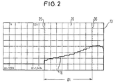
- FIG. 2 shows one shown on the screen 15 of the storage oscillograph 13 Course curve 16, the position of the reflector 5 and thus the Represents press body 2 over time and thus representative of the Movement of the press body 2 is.
- the movement can on the storage oscillograph 13 linear or in another way as a delay function representation can be evaluated in the X or Y direction or at surface movement, for example on a robot arm, too simultaneously in the X and Y directions.
- the measuring device is used for time measurement of the oscillograph 13 with its two catch lines 35 and 36 used on the screen 15. With a two-channel oscillograph can move in the X and Y directions by using the Both measuring channels can be assessed independently of one another.
- the stop time can be between the two catch lines 35 and 36 ⁇ t can be read.
- the light cone 9 can pass through the unit 6 and the reflector 5 to one another colored light should be formed so that its projection clearly on the surface of the press body 2 can be seen and the reflector 5 on the Press body 2 can be attached so that it is complete Braking the press body 2 still within the projected light cone 9 lies. With appropriate adaptation of the light cone 9 to the Catch area 10 is thus ensured that the reflector 5 after complete Braking the press body 2 still within the capture range 10 comes to rest.
- Fig. 3 is the system of FIG. 1 with various devices interconnected to generate the stop signal. This can be done in practice either only one of the devices for generating a stop signal be provided, or it is also possible to use several of those shown in FIG. 3 To provide devices at the same time in order in this way Achieve increased flexibility in stopping time measurement.
- Fig. 1 are shown in Fig. 3 with the same reference numerals we labeled in Fig. 1.
- Fig. 3 is a light grid 17 with a transmitter row 18 for generating Light rays 17 'and a row of receivers 19 arranged in front of the press 1, that there is an adequate security area 20 between the press 1 and the light grid 17 is present.
- the movement of the press body 2 is controlled by a machine control 21 controlled.
- a corresponding stop signal for the evaluation unit 12 of the stop time measuring system can be generated in different ways like it is explained below. It is advantageous that in all embodiments the stop signal is contactless and contactless with the actual one Press system is designed with protection zone monitoring.
- the receiver row 19 of the Light grating 17 a photosensitive receiver 25 is provided, so is arranged that he lights up an indicator lamp, not shown of the light grid 17 picks up.
- the indicator lamp lights up at one Interruption of the light beams 17 'of the light grid 17 so that this Protective field interruption is detected by the receiver 25 and a corresponding one Stop signal via a line 26 to the evaluation unit 12 is passed on.
- the stop signal is then the oscillograph 13 as synchronization signal characterizing the start of the stopping process fed.
- the output signal of the oscillograph 13 is sent to a Computer 14 for calculating the stop time .DELTA.t forwarded via a printer 34 connected to computer 14 in a measurement protocol can be printed out.
- the interruption of the protective field of the light grid 17 can be done by an engagement by means of an engagement element 27 of a rotary magnet 28 or a magnetic pin that can be controlled by the evaluation unit 12, respectively.
- the stop signal for the evaluation unit 12 can also be through a light barrier 29 are generated, for example when detecting the reflector 5 outputs a synchronization signal to the oscillograph 13 and initiates the standstill of the press body 2.
- a switch for example, on the rotary magnet 28 an engaging element designed as a switching flag is provided that engages in the light curtain 17. That from the switch The triggered signal can then be used as a stop signal for the evaluation unit 12 be used.
- the rotary magnet 28 can advantageously be triggered by a contact on the press 1, so that the measurement of the stop time depends on a certain position of the press body 2 begins.
- braking of the press body can occur 2 also via the light barrier 29 and the associated reflector, such as described above.
- a on the machine control 21 Switching relay 30 is provided, the switching of a magnetic Sensor 31 can be detected. If the press 1 is controlled by the machine control 21 switched off, this is recognized by the magnetic sensor 31 and a corresponding stop signal via a line 32 to the evaluation unit 12 passed.
- the stop signal for the evaluation unit 12 directly from the control unit 23 corresponding to that of the machine control 21 generated shutdown signal supplied via line 24 becomes.
- an electrical separation between the Control unit 23 and the evaluation unit 12 for example, by a Optocoupler, by inductive coupling or other suitable Generated way.
- the evaluation unit 12 can have one or more delay elements 33 include, through the desired delays within the measurement system can be adjusted. So it can happen that with the The light barrier 29 initiates the braking process, but the reflector 5 is not yet in the capture area 10 of the optical unit 6.
- the time can be lengthened by the delay element 33 in such a way that the reflector 5 within the capture area 10 to a standstill is coming.
- the movement can be done with a small catch area 10 of the reflector 5 are high-resolution and exactly determined if the delay time, for example, by using a quartz-controlled Cycle timer is known.
- Delay times can also be achieved with the measuring system according to the invention between individual switching elements as detected by the different Switching times of the switching chains shown are available can.
- Entire rotary movements can also be advantageous with the system according to the invention for example on a rotary table or on robots, being a horizontal and / or vertical movement for measurement without Meaning is. Even diagonal movements can be done with the invention System can be measured precisely.
- variable size of the capture region 10, which can be adjusted by correspondingly varying the distance between the reflector 5 and the optoelectronic unit 6, can preferably be used.
- the capture area 10 can be 50 x 50 cm 2 at a distance of one meter between the optoelectronic unit 6 and the reflector 5.
- the spatial resolution can be ⁇ 10 mm and is therefore precise enough to clarify questions regarding the safety distance or quality confirmations of the braking deceleration on the press 1.
- the distance between the reflector 5 and the optoelectronic unit 6 can then be reduced in order to make the measurement of the stop time ⁇ t more precise.
Landscapes
- Engineering & Computer Science (AREA)
- Mechanical Engineering (AREA)
- Physics & Mathematics (AREA)
- General Physics & Mathematics (AREA)
- Measurement Of Unknown Time Intervals (AREA)
- Time Recorders, Dirve Recorders, Access Control (AREA)
Abstract
Description
- Fig. 1
- eine schematische Darstellung eines Teils eines erfindungsgemäß ausgebildeten Systems zur Stoppzeitmessung,
- Fig. 2
- ein durch ein erfindungsgemäßes System gemäß Fig. 1 erzeugtes Oszillogramm zur Ermittlung der Stoppzeit und
- Fig. 3
- eine schematische Darstellung eines erfindungsgemäßen Systems zur Stoppzeitmessung mit mehreren unterschiedlichen Varianten zur Erzeugung des Stoppsignals.
- 1
- Presse
- 2
- Pressenkörper
- 3
- Pfeil
- 4
- Preßtisch
- 5
- Reflektor
- 6
- optoelektronische Einheit
- 7
- Optik
- 8
- Sensoreinheit
- 9
- Lichtkegel
- 9'
- Randstrahlen
- 10
- Fangbereich
- 11
- Verbindungsleitung
- 12
- Auswerteeinheit
- 13
- Speicheroszillograph
- 14
- Rechner
- 15
- Bildschirm
- 16
- Verlaufskurve
- 17
- Lichtgitter
- 17'
- Lichtstrahlen
- 18
- Senderreihe
- 19
- Empfängerreihe
- 20
- Sicherheitsbereich
- 21
- Maschinensteuerung
- 22
- Leitung
- 23
- Steuereinheit
- 24
- Leitung
- 25
- Empfänger
- 26
- Leitung
- 27
- Eingriffselement
- 28
- Drehmagnet
- 29
- Lichtschranke
- 30
- Schaltrelais
- 31
- magnetischer Sensor
- 32
- Leitung
- 33
- Verzögerungselement
- 34
- Drucker
- 35
- Fanglinie
- 36
- Fanglinie
Claims (12)
- System zum Erfassen der Stoppzeit (Δt) einer Vorrichtung (1) mit zumindest einem bewegbaren Teil (2), insbesondere einer Presse oder einer sonstigen kraftbetriebenen Vorrichtung, mit einer optoelektronischen Einheit (6), mit der zumindest ein Abschnitt (5) des bewegbaren Teils (2) optisch erfaßbar und ein zu der Bewegung des Teils (2) korrespondierendes Ausgangssignal erzeugbar ist, und mit einer mit der optoelektronischen Einheit (6) gekoppelten Auswerteeinheit (12), mit der ein den Beginn eines Stoppvorgangs der Vorrichtung (1) kennzeichnendes Stoppsignal aufnehmbar ist und abhängig von dem Ausgangssignal der optoelektronischen Einheit (6) die Zeitdauer vom Aufnehmen des Stoppsignals bis zum tatsächlichen Stillstand des bewegbaren Teils (2) ermittelbar ist.
- System nach Anspruch 1,
dadurch gekennzeichnet, daß mit der optoelektronischen Einheit (6) die jeweilige aktuelle Position des bewegbaren Teils (2) ermittelbar und als Ausgangssignal an die Auswerteeinheit (12) übermittelbar ist. - System nach Anspruch 2,
dadurch gekennzeichnet, daß die optoelektronische Einheit (6) eine ortsauflösende Sensoreinheit (8) zur Bestimmung der Position des bewegbaren Teils (2) umfaßt. - System nach einem der vorhergehenden Ansprüche,
dadurch gekennzeichnet, daß der Abschnitt des bewegbaren Teils (2) als Licht reflektierendes Element, insbesondere als Reflektor (5) ausgebildet ist. - System nach einem der vorhergehenden Ansprüche,
dadurch gekennzeichnet, daß die optoelektronische Einheit (6) eine Licht aussendende Sendeeinheit zum Aussenden von Licht (9) in Richtung des Abschnitts (5) des bewegbaren Teils (2) und eine Empfangseinheit (8) zum Empfangen von an dem bewegbaren Teil (2) reflektiertem Licht umfaßt. - System nach einem der vorhergehenden Ansprüche,
dadurch gekennzeichnet, daß die optoelektronische Einheit (6) zum Aussenden und Empfangen von sichtbarem Licht (9) und/oder von Licht im IR-Bereich und/oder von Licht im UV-Bereich ausgebildet ist. - System nach einem der vorhergehenden Ansprüche,
dadurch gekennzeichnet, daß die Auswerteeinheit (12) einen Oszillographen (13), insbesondere einen Speicheroszillographen umfaßt. - System nach Anspruch 7,
dadurch gekennzeichnet, daß die Auswerteeinheit (12) einen Rechner (14) umfaßt, der mit einem Ausgang des Oszillographen (13) verbunden und zum Ermitteln der Stoppzeit aus dem Ausgangssignal des Oszillographen (13) ausgebildet ist. - System nach einem der vorhergehenden Ansprüche,
dadurch gekennzeichnet, daß eine Stoppsignalerzeugungseinheit (25, 31, 28) vorgesehen ist, mit der das den Beginn des Stoppvorgangs der Vorrichtung (1) kennzeichnende Stoppsignal insbesondere berührungslos erzeugbar ist. - System nach Anspruch 9,
dadurch gekennzeichnet, daß die Stoppsignalerzeugungseinheit eine optoelektronische Einheit (25) zur Erzeugung des Stoppsignals umfaßt. - System nach Anspruch 9 oder 10,
dadurch gekennzeichnet, daß die Stoppsignalerzeugungseinheit eine induktive Einheit (31) zur Erzeugung des Stoppsignals umfaßt. - System nach Anspruch 9, 10 oder 11,
dadurch gekennzeichnet, daß die Stoppsignalerzeugungseinheit eine mechanische Einheit (28) zur Erzeugung des Stoppsignals umfaßt, an der ein Eingriffselement (27) zum Eingreifen in ein die Vorrichtung (1) absicherndes Schutzfeld, insbesondere eines Lichtgitters (17), vorgesehen ist.
Applications Claiming Priority (2)
| Application Number | Priority Date | Filing Date | Title |
|---|---|---|---|
| DE20006578U | 2000-04-10 | ||
| DE20006578U DE20006578U1 (de) | 2000-04-10 | 2000-04-10 | Stoppzeiterfassungssystem |
Publications (2)
| Publication Number | Publication Date |
|---|---|
| EP1145839A2 true EP1145839A2 (de) | 2001-10-17 |
| EP1145839A3 EP1145839A3 (de) | 2003-04-02 |
Family
ID=7940055
Family Applications (1)
| Application Number | Title | Priority Date | Filing Date |
|---|---|---|---|
| EP01108762A Withdrawn EP1145839A3 (de) | 2000-04-10 | 2001-04-06 | Stoppzeiterfassungssystem |
Country Status (2)
| Country | Link |
|---|---|
| EP (1) | EP1145839A3 (de) |
| DE (1) | DE20006578U1 (de) |
Families Citing this family (1)
| Publication number | Priority date | Publication date | Assignee | Title |
|---|---|---|---|---|
| DE102009010460B4 (de) | 2009-02-13 | 2010-11-25 | Pilz Gmbh & Co. Kg | Vorrichtung und Verfahren zum Bestimmen der Nachlaufzeit einer Maschine |
Family Cites Families (9)
| Publication number | Priority date | Publication date | Assignee | Title |
|---|---|---|---|---|
| DD116090A1 (de) | 1974-11-13 | 1975-11-05 | ||
| US3993898A (en) * | 1975-12-17 | 1976-11-23 | Babcock & Wilcox Limited | Press brake performance tester |
| US4177517A (en) * | 1976-07-07 | 1979-12-04 | Mette Klaus H | Monitoring device for power presses |
| GB1602178A (en) * | 1977-04-20 | 1981-11-11 | Marconi Co Ltd | Apparatus for testing the braking of a moving machine part |
| SE449520B (sv) | 1985-09-04 | 1987-05-04 | Inst Verkstadstek Forsk Ivf | Sett att meta stopptid och stoppstrecka hos en rorlig del av en maskin och anordning for genomforande av settet |
| DE3532197A1 (de) | 1985-09-10 | 1987-03-12 | Leuze Electronic Gmbh & Co | Lichtvorhang |
| JPS63500822A (ja) | 1986-01-13 | 1988-03-24 | デ−タ・インストルメント・インコ−ポレ−テッド | 産業機械を作動するための侵入検出システム |
| US5218196A (en) | 1991-09-05 | 1993-06-08 | Frost Controls, Inc. | Light curtain system with system and watchdog microcontrollers |
| US5245178A (en) | 1992-08-21 | 1993-09-14 | Magnetek Controls | Apparatus for automatically testing safety light curtain and measuring machine stoppage time |
-
2000
- 2000-04-10 DE DE20006578U patent/DE20006578U1/de not_active Expired - Lifetime
-
2001
- 2001-04-06 EP EP01108762A patent/EP1145839A3/de not_active Withdrawn
Also Published As
| Publication number | Publication date |
|---|---|
| DE20006578U1 (de) | 2000-07-20 |
| EP1145839A3 (de) | 2003-04-02 |
Similar Documents
| Publication | Publication Date | Title |
|---|---|---|
| EP1300691B1 (de) | Überwachungsverfahren und optoelektronischer Sensor | |
| DE19938639B4 (de) | Vorrichtung zur Absicherung eines Gefahrenbereichs, insbesondere des Gefahrenbereichs einer automatisiert arbeitenden Maschine | |
| EP2093734B1 (de) | Rauchmelder mit zeitlicher Auswertung eines Rückstreusignals, Testverfahren für Funktionsfähigkeit eines Rauchmelders | |
| EP0902402B1 (de) | Verfahren und Vorrichtung zur optischen Überwachung eines Raumbereichs | |
| EP1345444A1 (de) | Video Überwachungssystem mittels 3-D Halbleiterbildsensor und Infra-Rot Lichtquelle | |
| EP2180348A1 (de) | Lichtgitter | |
| EP1046925A1 (de) | Optoelektronische Vorrichtung | |
| DE4326640C2 (de) | Meßeinrichtung für den Weg eines beweglichen Teils an einem elektrischen Schaltgerät und Verfahren zum Betrieb eines Schaltgeräts mit einer Meßeinrichtung | |
| DE19504714A1 (de) | Verfahren und Vorrichtung zur Überwachung einer Zustandsgröße eines Leistungsschalters | |
| DE3908273C1 (en) | Self-test device for a scanning light probe | |
| EP3736605B1 (de) | Sicherheitslaserscanner und verfahren | |
| DE10059837A1 (de) | Impuls- und fluoreszenz-tolerantes 3D-Sicherheitsdetektionssystem für Aufzugschiebetüren | |
| EP3460533B1 (de) | Optoelektronischer sensor und verfahren zur erfassung von transparenten objekten | |
| DE102009010460B4 (de) | Vorrichtung und Verfahren zum Bestimmen der Nachlaufzeit einer Maschine | |
| DE4131819A1 (de) | Messeinrichtung zur bestimmung des weges an elektrischen schaltgeraeten | |
| EP1145839A2 (de) | Stoppzeiterfassungssystem | |
| EP2244094B1 (de) | Vorrichtung und Verfahren zum Überprüfen eines Schaltvorgangs eines elektrischen Schalters | |
| DE3526206A1 (de) | Wegmesseinrichtung | |
| DE202006012637U1 (de) | Vorrichtung zum Kollisionsschutz zwischen aufeinanderfolgenden spurgeführten Fahrzeugen | |
| EP0490012A1 (de) | Sensor-System zur Überwachung von Kranen | |
| DE29503914U1 (de) | Störlichtbogen-Erfassungseinrichtung für Schaltanlagen zur Verteilung elektrischer Energie | |
| DE3203720C2 (de) | Gerät zur Erkennung von auf Gegenständen angebrachten, optischen Codemarken | |
| EP1480060B1 (de) | Optischer Sensor | |
| EP0039424A2 (de) | Justieranordnung für Lichtgitter | |
| EP1160751A1 (de) | Bewegungsmelder |
Legal Events
| Date | Code | Title | Description |
|---|---|---|---|
| PUAI | Public reference made under article 153(3) epc to a published international application that has entered the european phase |
Free format text: ORIGINAL CODE: 0009012 |
|
| AK | Designated contracting states |
Kind code of ref document: A2 Designated state(s): AT BE CH CY DE DK ES FI FR GB GR IE IT LI LU MC NL PT SE TR |
|
| AX | Request for extension of the european patent |
Free format text: AL;LT;LV;MK;RO;SI |
|
| PUAL | Search report despatched |
Free format text: ORIGINAL CODE: 0009013 |
|
| AK | Designated contracting states |
Kind code of ref document: A3 Designated state(s): AT BE CH CY DE DK ES FI FR GB GR IE IT LI LU MC NL PT SE TR Designated state(s): AT BE CH CY DE DK ES FI FR GB GR IE IT LI LU MC NL PT SE TR |
|
| AX | Request for extension of the european patent |
Extension state: AL LT LV MK RO SI |
|
| RIC1 | Information provided on ipc code assigned before grant |
Ipc: 7G 01P 3/36 B Ipc: 7B 30B 15/28 A |
|
| AKX | Designation fees paid | ||
| REG | Reference to a national code |
Ref country code: DE Ref legal event code: 8566 |
|
| STAA | Information on the status of an ep patent application or granted ep patent |
Free format text: STATUS: THE APPLICATION IS DEEMED TO BE WITHDRAWN |
|
| 18D | Application deemed to be withdrawn |
Effective date: 20031003 |