EP1145767A2 - Dosiervorrichtung für eine Lösung - Google Patents
Dosiervorrichtung für eine Lösung Download PDFInfo
- Publication number
- EP1145767A2 EP1145767A2 EP01106152A EP01106152A EP1145767A2 EP 1145767 A2 EP1145767 A2 EP 1145767A2 EP 01106152 A EP01106152 A EP 01106152A EP 01106152 A EP01106152 A EP 01106152A EP 1145767 A2 EP1145767 A2 EP 1145767A2
- Authority
- EP
- European Patent Office
- Prior art keywords
- container
- dosing device
- fit
- fitting
- dosing
- Prior art date
- Legal status (The legal status is an assumption and is not a legal conclusion. Google has not performed a legal analysis and makes no representation as to the accuracy of the status listed.)
- Withdrawn
Links
- XLYOFNOQVPJJNP-UHFFFAOYSA-N water Substances O XLYOFNOQVPJJNP-UHFFFAOYSA-N 0.000 claims abstract description 57
- 239000007788 liquid Substances 0.000 claims abstract description 36
- 239000012530 fluid Substances 0.000 claims abstract description 30
- 239000000203 mixture Substances 0.000 claims abstract description 21
- 230000001105 regulatory effect Effects 0.000 claims abstract description 10
- 238000010438 heat treatment Methods 0.000 claims abstract description 7
- 238000009834 vaporization Methods 0.000 claims abstract description 6
- 230000008016 vaporization Effects 0.000 claims abstract description 6
- GCLGEJMYGQKIIW-UHFFFAOYSA-H sodium hexametaphosphate Chemical compound [Na]OP1(=O)OP(=O)(O[Na])OP(=O)(O[Na])OP(=O)(O[Na])OP(=O)(O[Na])OP(=O)(O[Na])O1 GCLGEJMYGQKIIW-UHFFFAOYSA-H 0.000 claims description 4
- 235000019982 sodium hexametaphosphate Nutrition 0.000 claims description 4
- 239000001577 tetrasodium phosphonato phosphate Substances 0.000 claims description 4
- 230000000295 complement effect Effects 0.000 claims description 2
- 239000000843 powder Substances 0.000 claims description 2
- 230000002093 peripheral effect Effects 0.000 claims 4
- 238000011144 upstream manufacturing Methods 0.000 description 10
- 229920000388 Polyphosphate Polymers 0.000 description 8
- 239000006028 limestone Substances 0.000 description 8
- 239000001205 polyphosphate Substances 0.000 description 8
- 235000011176 polyphosphates Nutrition 0.000 description 8
- 239000000243 solution Substances 0.000 description 8
- 235000019738 Limestone Nutrition 0.000 description 7
- 230000015572 biosynthetic process Effects 0.000 description 5
- 238000005755 formation reaction Methods 0.000 description 5
- 238000011282 treatment Methods 0.000 description 5
- 230000008878 coupling Effects 0.000 description 4
- 238000010168 coupling process Methods 0.000 description 4
- 238000005859 coupling reaction Methods 0.000 description 4
- BHPQYMZQTOCNFJ-UHFFFAOYSA-N Calcium cation Chemical compound [Ca+2] BHPQYMZQTOCNFJ-UHFFFAOYSA-N 0.000 description 3
- 229910001424 calcium ion Inorganic materials 0.000 description 3
- 239000012895 dilution Substances 0.000 description 3
- 238000010790 dilution Methods 0.000 description 3
- 238000012423 maintenance Methods 0.000 description 3
- 230000002776 aggregation Effects 0.000 description 2
- 238000004220 aggregation Methods 0.000 description 2
- 238000009434 installation Methods 0.000 description 2
- 238000004519 manufacturing process Methods 0.000 description 2
- 230000000750 progressive effect Effects 0.000 description 2
- 230000033228 biological regulation Effects 0.000 description 1
- 239000003795 chemical substances by application Substances 0.000 description 1
- 230000007797 corrosion Effects 0.000 description 1
- 238000005260 corrosion Methods 0.000 description 1
- 230000006866 deterioration Effects 0.000 description 1
- 235000000396 iron Nutrition 0.000 description 1
- 238000010409 ironing Methods 0.000 description 1
- 238000006116 polymerization reaction Methods 0.000 description 1
- 238000001556 precipitation Methods 0.000 description 1
- 230000007425 progressive decline Effects 0.000 description 1
- 239000013049 sediment Substances 0.000 description 1
- 229910001415 sodium ion Inorganic materials 0.000 description 1
- RYFMWSXOAZQYPI-UHFFFAOYSA-K trisodium phosphate Chemical class [Na+].[Na+].[Na+].[O-]P([O-])([O-])=O RYFMWSXOAZQYPI-UHFFFAOYSA-K 0.000 description 1
Images
Classifications
-
- E—FIXED CONSTRUCTIONS
- E03—WATER SUPPLY; SEWERAGE
- E03C—DOMESTIC PLUMBING INSTALLATIONS FOR FRESH WATER OR WASTE WATER; SINKS
- E03C1/00—Domestic plumbing installations for fresh water or waste water; Sinks
- E03C1/02—Plumbing installations for fresh water
- E03C1/04—Water-basin installations specially adapted to wash-basins or baths
- E03C1/046—Adding soap, disinfectant, or the like in the supply line or at the water outlet
-
- B—PERFORMING OPERATIONS; TRANSPORTING
- B01—PHYSICAL OR CHEMICAL PROCESSES OR APPARATUS IN GENERAL
- B01F—MIXING, e.g. DISSOLVING, EMULSIFYING OR DISPERSING
- B01F25/00—Flow mixers; Mixers for falling materials, e.g. solid particles
- B01F25/30—Injector mixers
- B01F25/31—Injector mixers in conduits or tubes through which the main component flows
- B01F25/316—Injector mixers in conduits or tubes through which the main component flows with containers for additional components fixed to the conduit
-
- B—PERFORMING OPERATIONS; TRANSPORTING
- B01—PHYSICAL OR CHEMICAL PROCESSES OR APPARATUS IN GENERAL
- B01F—MIXING, e.g. DISSOLVING, EMULSIFYING OR DISPERSING
- B01F2101/00—Mixing characterised by the nature of the mixed materials or by the application field
- B01F2101/06—Mixing of food ingredients
-
- B—PERFORMING OPERATIONS; TRANSPORTING
- B01—PHYSICAL OR CHEMICAL PROCESSES OR APPARATUS IN GENERAL
- B01F—MIXING, e.g. DISSOLVING, EMULSIFYING OR DISPERSING
- B01F25/00—Flow mixers; Mixers for falling materials, e.g. solid particles
- B01F25/30—Injector mixers
- B01F25/31—Injector mixers in conduits or tubes through which the main component flows
- B01F25/312—Injector mixers in conduits or tubes through which the main component flows with Venturi elements; Details thereof
Definitions
- the present invention refers to devices used in water and liquid treatments.
- the invention refers to the realization of an enhanced dosing device for liquids, fit to be used in waterworks for the water heating and/or vaporization for industrial or domestic or sanitary uses; or however in the water circuits in which flows a fluid fit to be treated with a solution.
- Such dosing device can be used, for instance, in the circuits for feeding liquid to boilers, boilers for ironing machines, laundries and machines for making drinks, such as percolators.
- the aggregation of said calcium ions produces the so-called limestone that sediments on the inner walls of the water piping, causing the progressive reduction of the internal section of this latter up to the undesired occlusion, and that causes the corrosion of the same piping.
- the heating and/or the vaporization waterworks need periodical maintenance that, if not executed, causes the rapid deterioration of the related water circuits, particularly of the small section piping. Furthermore, occlusions of possible safety valves, fit in said waterworks, may occur with the consequent reduction of the global safety factor of the waterworks up to constitute a danger for the operators.
- the water may be treated by using decalcifier agents, such as for instance the polyphosphates, particularly obtained by polymerization of the sodium monophosphates.
- decalcifier agents such as for instance the polyphosphates, particularly obtained by polymerization of the sodium monophosphates.
- Such polyphosphates, mixed with the water react with the calcium ions, avoiding their aggregation and therefore the limestone formation, liberating sodium ions at the same time.
- the dosing device object of the Italian patent application n. BO97A 000633 is provided with a fitting, to be fit in series with the feeding piping of the circuit, and with a container of the solution which is dosed by virtue of the interposition of diverter means positioned between the fitting and the container.
- the fitting has a central throttling in order to realize a pressure difference between the upstream and downstream sections of said fitting.
- this fitting further has an offtake through which part of the fluid, which runs in the piping, flows and ends into the container through the diverter means, so mixing itself with the solution present inside said container.
- the main drawback of the known dosing device consists in that the diverter means have a water inlet channel from the upstream offtake toward the inside of the container and an outflow channel of the mixture water- dosing liquid from the container toward the downstream offtake which have a very sinuous shape, so making extremely turbulent the fluid flow inside said channels.
- the main object of the present invention is to propose an enhanced dosing device fit to avoid or at least minimize the slowdowns, the stagnation and the lack of homogeneities of the flow, occurring inside the diverter means.
- Another object of the present invention is to propose a dosing device fit to avoid or at least to reduce the dilution of the dosing liquid of the container that follows the pressure increases of the fluid flowing in the hydraulic circuit in which is fit the dosing device, such as for instance the water hammers.
- Another object is to propose a dosing device enabling an extremely homogeneous and constant water treatment, guaranteeing that the quantity of treated water always contains a polyphosphate percentage lower than the limits allowed by the legislation in force in the matter.
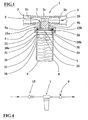
- numeral 1 indicates a dosing device for a dosing liquid 8 in a feeding fluid 29, particularly water, that flows in heating or vaporization waterworks for sanitary or alimentary use, both industrial and domestic.
- the dosing device 1 essentially includes a fitting 2, a closing element 4, a container 6, a splashguard ring 30 and diverter means 7.
- the fitting 2 has a throttling 2a of around 3 mm of the inner section centrally positioned, and whose ends can be jointed to a feeding duct 3, by means of truncated conical portions 2b starting from the throttling ends and whose biggest diameter is 8,5 mm, in correspondence of the duct 3, and whose smallest diameter is 8 mm in correspondence of the throttling 2a.
- the closing element 4, associated to the fitting 2 is provided with a couple of regulating ducts 5, an inlet duct 5a and an outflow duct 5b, respectively positioned upstream and downstream the throttling 2a and precisely in proximity of the inlet and outlet sections of this latter, and fit for the flow communication between the inside of the fitting 2 with the inside of the container 6.
- a gasket 21 positioned between the closing element 4 and the diverter means 7.
- indicator element 22 spherical shaped, having a specific weight slightly higher than the specific weight of the feeding fluid 29, but lower than that one of the dosing liquid 8.
- the diverter means 7 are interposed between the closing element 4 and the container 6 and they are supported by. a raised external edge 31 of the splashguard ring 30 which is supported by a shoulder 39 carried out in the inner wall of the container 6 in proximity of its upper opening.
- Said diverter means 7 are fit to direct predetermined quantity of the feeding fluid at first through an inlet path included between the fitting 2 and the container 6, through an inlet duct 5a, and afterwards to direct an equal amount of mixture of the feeding fluid with the dosing liquid 8 through an outflow path, included between the container 6 and the fitting 2, by means of an outflow duct 5b.
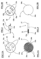
- the splashguard ring 30 has a circular edge 33 protruding inside the container 6 and having a groove 32 fit to face the diverter means 7 in correspondence of a couple of holes 20a and 20b.
- the diverter means 7 include an upper element 10 including a circular shaped support base 14, from which two bent fins 12a and 12b protrude, each of said fins having a flat top on which are made a couple of holes, respectively 13a and 13b, connecting respectively the inlet duct 5a and the outflow duct 5b.
- the closing element 4 is internally provided with a circular crown 26 within which the holes 13a and 13b are positioned and around which the gasket 21 is arranged so that to realize a watertight coupling between the container 6 and the closing element 4.
- the diverter means 7 further include a lower element 11 constituted by a circular shaped base 23 provided with a raised side edge 23a joinable, in a complementary and univocal way, with the support base 14.
- Said base 23 has the couple of holes 20a and 20b, which are diametrically opposed and fit for connecting respectively the holes 13a and 13b with the inside of the container 6, by interposing a couple of spiral shaped coils 16, concentrically positioned between them and having a shared end.
- the coils 16 define a couple of channels, inlet 24a and outflow 24b, being respectively an inlet path into the container 6 for the feeding fluid 29 and an outflow path from the container 6 of the mixture of feeding fluid 29 and of dosing liquid 8.
- Each of these channels 24a and 24b has a blind end, positioned in correspondence of the central portion of the base 23 while, in proximity of the other end there is the related hole 20a or 20b executed on the base 23.
- the facing walls of a related coil, the support base 14 and the base 23 thus constitute these channels 24a and 24b.
- the holes 13a and 13b are positioned on each of said channels, inlet 24a and outflow 24b, by virtue of the univocal coupling between the outflow elements, upper 10 and lower 11, carried out by means of a pin 17 protruding from the side edge 23a and lockable in a corresponding slot 18 on the external edge of the support base 14.
- the operation of the dosing device 1 is simple because the feeding fluid 29, for instance water, coming from the portion of the feeding duct upstream the throttling 2a is forced to flow through this latter up to the downstream portion of the feeding duct 3.
- the presence of the throttling 2a determines a pressure difference between the upstream section and the downstream section of said throttling, in correspondence of the sections of the regulating ducts 5 and precisely a upstream pressure greater than the downstream section.
- This hydrodynamic phenomenon causes the piping of a water portion which flows into the portion of the feeding duct 3 upstream the throttling 2a toward the inlet duct 5a and therefore toward one or both of the holes 13a on the upper element 10 of the diverter means 7.
- the water flows in the inlet channel 24a and therefore flows along the spiral path of this latter up to reach the hole 20a from which the water flows into the container 6 by interposing the splashguard ring 30.
- the water spout coming out from the hole 20a ends on the groove 32 of the splashguard ring 30 below and therefore its inlet trajectory into the container 6 is diverted toward the central portion of this latter and has a reduced intensity.
- a same amount of mixture so obtained by mixing the water and the dosing liquid 8 follows the path in the reverse direction in comparison with the preceding direction, sucked by the existing depression downstream the throttling 2a, flowing in the outflow channel 24b through the hole 20b and therefore flowing into the outflow duct 5b through the two holes 13b until it flows into the portion of feeding duct 3 downstream the throttling 2a.
- the amount of mixture water-liquid 8 flows and disperses in the fluid flow, or better in the water flow, that flows downstream the throttling 2a, so making the water treatment.
- Both the water flow inside the inlet channel 24a and the mixture flow inside the outflow channel 24b are characterized in that they are almost laminar or however not much turbulent by virtue of the spiral shape of the inlet and outflow channels. In this way the flow resistances are very low and a great uniformity of solution dosing inside the water can be achieved.
- the splashguard ring 30 is particularly effective in the opening/closing conditions of the hydraulic circuit in which the dosing device is fit, since these conditions might cause sudden and conspicuous pressure increases inside the circuit piping, which generate the so-called water hammers.
- the water spout flowing into the container 6 by means of the hole 20a has an high pressure force that is damped by means of the groove 32 of the ring 30 which diverts the water spout.
- the water spout even with a water hammer, does not reach the dosing liquid contained in proximity of the container bottom and therefore it does not dilute said dosing liquid, and consequently the splashguard ring guarantees a more uniform final dosing of the solution in the water.
- the liquid 8 is constituted by a powder mixture based on sodium hexametaphosphate for food use, for instance diluted in water in the proportions of 33% of sodium hexametaphosphate and the remaining 66% of water. Said mixture has about 1,3 Kg/dm 3 specific weight.
- the regulating ducts 5 have a diameter between 0,5 and 3,5 mm, preferably 3 mm, in order to optimize the regulation of the water and mixture amount flowing through said regulating ducts in order to avoid that the amount of polyphosphates in the mixture fluid-liquid, that is water and polyphosphates which is mixed with water downstream the throttling 2a, exceeds the limits settled at 5 mg/l allowed by the legislation in the matter.
- the regulating ducts 5 have a diameter ranging from 1/12 to 1/3 of the internal diameter of the duct 2.
- the diameter of the throttling 2a is 3 mm and the diameter of the regulating ducts is 1 mm.
- the specific weight of the indicator element 22 is greater than the specific weight of said feeding fluid of a percentage quantity ranging from 1% to 5%. Particularly if the feeding fluid is water, then the specific weight of the indicator element 22 is ranging from 1,01 to 1,05 Kg/dm 3 . This facilitates the progressive movement of the indicator element 22 toward the bottom of the container 6 because the mixture water-dosing liquid 8 becomes poor of the active element, the polyphosphate, while at the same time said mixture enriches in water causing a progressive decrease of the specific weight of said mixture up to reach a value close to the water value. In such condition the indicator element is positioned in proximity of the container bottom therefore acting like a display element of the concentration of the water-liquid mixture inside the container and the need of replacing its content with a new amount of dosing liquid 8.
- the replacement of the dosing liquid 8 inside the container can be facilitated if a check valve 15 is fit in the feeding water circuit upstream of the dosing device 1; said check valve, when activated, interrupts the water passage in the water circuit.
- a vent valve is further fit, for the air eventually entered into the piping, particularly into the container 6, following the uncoupling and coupling operations of this latter with the closing element 4 of the dosing device 1, needed for substituting the dosing liquid 8 inside said container.
- the device 1 can be easily and advantageously fit upstream the feeding circuit of coffee machine, boilers for the steam production, for instance for irons, and boilers for the hot water production as well.
- the main advantage of the present invention is that to provide enhanced dosing device fit to avoid or at least minimize the flow losses inside the diverter means and thus the slowdowns, the stagnation and the lack of homogeneity of the flow.
- Another advantage of the present invention is to provide a dosing device fit to avoid or at least to reduce the dilution of the dosing liquid of the container following the pressure increases of the fluid flowing in the hydraulic circuit in which the dosing device is fit, such as for instance the water hammers.
- Another advantage is to provide a dosing device that enables an extremely homogeneous and constant water treatment, guaranteeing that the amount of treated water contains a polyphosphate percentage always lower than the limits allowed by the legislation in force in the matter.
Landscapes
- Health & Medical Sciences (AREA)
- Life Sciences & Earth Sciences (AREA)
- Engineering & Computer Science (AREA)
- Hydrology & Water Resources (AREA)
- Public Health (AREA)
- Water Supply & Treatment (AREA)
- Chemical & Material Sciences (AREA)
- Chemical Kinetics & Catalysis (AREA)
- Cookers (AREA)
- Devices For Dispensing Beverages (AREA)
- External Artificial Organs (AREA)
Applications Claiming Priority (2)
| Application Number | Priority Date | Filing Date | Title |
|---|---|---|---|
| IT2000BO000132A IT1320918B1 (it) | 2000-03-13 | 2000-03-13 | Dispositivo dosatore di una soluzione. |
| ITBO200132 | 2000-03-13 |
Publications (2)
| Publication Number | Publication Date |
|---|---|
| EP1145767A2 true EP1145767A2 (de) | 2001-10-17 |
| EP1145767A3 EP1145767A3 (de) | 2004-12-01 |
Family
ID=11438302
Family Applications (1)
| Application Number | Title | Priority Date | Filing Date |
|---|---|---|---|
| EP01106152A Withdrawn EP1145767A3 (de) | 2000-03-13 | 2001-03-13 | Dosiervorrichtung für eine Lösung |
Country Status (2)
| Country | Link |
|---|---|
| EP (1) | EP1145767A3 (de) |
| IT (1) | IT1320918B1 (de) |
Cited By (5)
| Publication number | Priority date | Publication date | Assignee | Title |
|---|---|---|---|---|
| GB2431711A (en) * | 2005-10-31 | 2007-05-02 | Richard Strong | Central heating inhibitor applicator |
| WO2011003476A1 (en) * | 2009-07-10 | 2011-01-13 | Ydroteq Nv | A dosing system and a cartridge |
| CN108854684A (zh) * | 2018-07-10 | 2018-11-23 | 芜湖喜源味食品有限公司 | 一种压榨、搅拌一体化食品加工搅拌装置 |
| WO2022125379A1 (en) * | 2020-12-07 | 2022-06-16 | Rheem Manufacturing Company | Liquid concentrate dosing systems |
| US12139429B2 (en) | 2020-12-07 | 2024-11-12 | Rheem Manufacturing Company | Scaling treatment systems for water heaters |
Family Cites Families (7)
| Publication number | Priority date | Publication date | Assignee | Title |
|---|---|---|---|---|
| US2188066A (en) * | 1937-10-02 | 1940-01-23 | Pyrene Minimax Corp | Apparatus for injecting foam stabilizing solutions |
| US2507410A (en) * | 1946-08-29 | 1950-05-09 | Clayton T Kemp | Mixing nozzle |
| GB688322A (en) * | 1949-10-17 | 1953-03-04 | Waldemar Foerstner | Feeding apparatus for mixing a liquid with another liquid flowing under pressure |
| GB800279A (en) * | 1955-10-18 | 1958-08-20 | Hugh Noel Mcnair | Liquid proportioning device |
| FR1205037A (fr) * | 1957-10-29 | 1960-01-29 | Benckiser Gmbh Joh A | Dispositif destiné à préserver les chauffe-eau de l'entartrage |
| GB936956A (en) * | 1960-05-20 | 1963-09-18 | Ronald Sidney Garwood | Improvements in or relating to liquid dispensing apparatus |
| FR2048359A5 (en) * | 1970-03-09 | 1971-03-19 | Kirmann Roger | Anti-scaling liquid mixer |
-
2000
- 2000-03-13 IT IT2000BO000132A patent/IT1320918B1/it active
-
2001
- 2001-03-13 EP EP01106152A patent/EP1145767A3/de not_active Withdrawn
Cited By (6)
| Publication number | Priority date | Publication date | Assignee | Title |
|---|---|---|---|---|
| GB2431711A (en) * | 2005-10-31 | 2007-05-02 | Richard Strong | Central heating inhibitor applicator |
| WO2011003476A1 (en) * | 2009-07-10 | 2011-01-13 | Ydroteq Nv | A dosing system and a cartridge |
| CN108854684A (zh) * | 2018-07-10 | 2018-11-23 | 芜湖喜源味食品有限公司 | 一种压榨、搅拌一体化食品加工搅拌装置 |
| WO2022125379A1 (en) * | 2020-12-07 | 2022-06-16 | Rheem Manufacturing Company | Liquid concentrate dosing systems |
| US11866915B2 (en) | 2020-12-07 | 2024-01-09 | Rheem Manufacturing Company | Liquid concentrate dosing systems |
| US12139429B2 (en) | 2020-12-07 | 2024-11-12 | Rheem Manufacturing Company | Scaling treatment systems for water heaters |
Also Published As
| Publication number | Publication date |
|---|---|
| ITBO20000132A1 (it) | 2001-09-13 |
| IT1320918B1 (it) | 2003-12-10 |
| EP1145767A3 (de) | 2004-12-01 |
Similar Documents
| Publication | Publication Date | Title |
|---|---|---|
| US20250223786A1 (en) | Liquid control apparatus and related methods | |
| US4173296A (en) | Apparatus for mixing and dispensing a beverage | |
| EP1145767A2 (de) | Dosiervorrichtung für eine Lösung | |
| US6182681B1 (en) | Automatic dry granular chemical dispenser | |
| TW202338186A (zh) | 用於分配水之混合水龍頭 | |
| KR20040010560A (ko) | 고속 유동/저속 유동 혼합 및 분배 장치 | |
| AU2013341306B2 (en) | Fluid injection system | |
| EP1827708B1 (de) | Abgabevorrichtung für verdünnungschemikalien mit verstellbarer wasserströmung | |
| US4921640A (en) | Venturi-tube bubble-forming container | |
| CA2430455C (en) | Apparatus for mixing two fluids or keeping them separate | |
| US2527848A (en) | Liquid mixing and dispensing apparatus | |
| EP3003957B1 (de) | Mischdüse | |
| CN210043967U (zh) | 分配器 | |
| RU2304993C2 (ru) | Смеситель и устройство пожаротушения | |
| US2946519A (en) | Liquid mixing apparatus | |
| US1879582A (en) | Fluid mixing device | |
| JP2012001274A (ja) | ウオーターサーバー用湯冷混合栓 | |
| JP2008289978A (ja) | 混合液供給装置 | |
| ITBO970633A1 (it) | Dosatore di una soluzione. | |
| CN213405172U (zh) | 用于洗头机的供液系统 | |
| US20220315461A1 (en) | Multifunction bypass dispensing system | |
| CN208703230U (zh) | 一种水龙头 | |
| CN201418971Y (zh) | 一种压差平衡式比例混合装置 | |
| US149230A (en) | Improvement in soda-water faucets | |
| JP2017079948A (ja) | 混合液供給装置 |
Legal Events
| Date | Code | Title | Description |
|---|---|---|---|
| PUAI | Public reference made under article 153(3) epc to a published international application that has entered the european phase |
Free format text: ORIGINAL CODE: 0009012 |
|
| AK | Designated contracting states |
Kind code of ref document: A2 Designated state(s): AT BE CH CY DE DK ES FI FR GB GR IE IT LI LU MC NL PT SE TR |
|
| AX | Request for extension of the european patent |
Free format text: AL;LT;LV;MK;RO;SI |
|
| PUAL | Search report despatched |
Free format text: ORIGINAL CODE: 0009013 |
|
| AK | Designated contracting states |
Kind code of ref document: A3 Designated state(s): AT BE CH CY DE DK ES FI FR GB GR IE IT LI LU MC NL PT SE TR |
|
| AX | Request for extension of the european patent |
Extension state: AL LT LV MK RO SI |
|
| RIC1 | Information provided on ipc code assigned before grant |
Ipc: 7F 24D 19/00 B Ipc: 7B 01F 1/00 B Ipc: 7B 01F 5/04 A |
|
| AKX | Designation fees paid | ||
| REG | Reference to a national code |
Ref country code: DE Ref legal event code: 8566 |
|
| STAA | Information on the status of an ep patent application or granted ep patent |
Free format text: STATUS: THE APPLICATION IS DEEMED TO BE WITHDRAWN |
|
| 18D | Application deemed to be withdrawn |
Effective date: 20050602 |