EP1143641B1 - Verfahren und gerät zur übertragung einer nachricht in einem mobilen kommunikationssystem - Google Patents
Verfahren und gerät zur übertragung einer nachricht in einem mobilen kommunikationssystem Download PDFInfo
- Publication number
- EP1143641B1 EP1143641B1 EP99969554A EP99969554A EP1143641B1 EP 1143641 B1 EP1143641 B1 EP 1143641B1 EP 99969554 A EP99969554 A EP 99969554A EP 99969554 A EP99969554 A EP 99969554A EP 1143641 B1 EP1143641 B1 EP 1143641B1
- Authority
- EP
- European Patent Office
- Prior art keywords
- mobile
- radiation
- communication means
- repeater
- message
- Prior art date
- Legal status (The legal status is an assumption and is not a legal conclusion. Google has not performed a legal analysis and makes no representation as to the accuracy of the status listed.)
- Expired - Lifetime
Links
- 238000010295 mobile communication Methods 0.000 title claims description 60
- 238000000034 method Methods 0.000 title claims description 23
- 230000005855 radiation Effects 0.000 claims description 75
- 238000004891 communication Methods 0.000 claims description 48
- 230000005670 electromagnetic radiation Effects 0.000 claims description 26
- 230000004907 flux Effects 0.000 claims description 8
- 230000005540 biological transmission Effects 0.000 description 22
- 230000008569 process Effects 0.000 description 8
- 238000010586 diagram Methods 0.000 description 7
- 230000008859 change Effects 0.000 description 5
- 230000006870 function Effects 0.000 description 5
- 230000001413 cellular effect Effects 0.000 description 4
- 230000015654 memory Effects 0.000 description 4
- 230000009471 action Effects 0.000 description 3
- 230000004913 activation Effects 0.000 description 3
- 231100001261 hazardous Toxicity 0.000 description 3
- 230000036541 health Effects 0.000 description 3
- 230000011664 signaling Effects 0.000 description 3
- 230000008901 benefit Effects 0.000 description 2
- 230000004044 response Effects 0.000 description 2
- QVWYCTGTGHDWFQ-AWEZNQCLSA-N (2s)-2-[[4-[2-chloroethyl(2-methylsulfonyloxyethyl)amino]benzoyl]amino]pentanedioic acid Chemical compound CS(=O)(=O)OCCN(CCCl)C1=CC=C(C(=O)N[C@@H](CCC(O)=O)C(O)=O)C=C1 QVWYCTGTGHDWFQ-AWEZNQCLSA-N 0.000 description 1
- IRLPACMLTUPBCL-KQYNXXCUSA-N 5'-adenylyl sulfate Chemical compound C1=NC=2C(N)=NC=NC=2N1[C@@H]1O[C@H](COP(O)(=O)OS(O)(=O)=O)[C@@H](O)[C@H]1O IRLPACMLTUPBCL-KQYNXXCUSA-N 0.000 description 1
- 229920000049 Carbon (fiber) Polymers 0.000 description 1
- 206010028980 Neoplasm Diseases 0.000 description 1
- 230000002146 bilateral effect Effects 0.000 description 1
- 230000031018 biological processes and functions Effects 0.000 description 1
- 210000004556 brain Anatomy 0.000 description 1
- 201000011510 cancer Diseases 0.000 description 1
- 239000004917 carbon fiber Substances 0.000 description 1
- 238000007796 conventional method Methods 0.000 description 1
- 208000037265 diseases, disorders, signs and symptoms Diseases 0.000 description 1
- 230000000694 effects Effects 0.000 description 1
- 230000008030 elimination Effects 0.000 description 1
- 238000003379 elimination reaction Methods 0.000 description 1
- 210000000750 endocrine system Anatomy 0.000 description 1
- 210000003743 erythrocyte Anatomy 0.000 description 1
- 239000000945 filler Substances 0.000 description 1
- 208000021245 head disease Diseases 0.000 description 1
- 238000005286 illumination Methods 0.000 description 1
- 230000036039 immunity Effects 0.000 description 1
- 230000006872 improvement Effects 0.000 description 1
- 230000000266 injurious effect Effects 0.000 description 1
- 229910052741 iridium Inorganic materials 0.000 description 1
- GKOZUEZYRPOHIO-UHFFFAOYSA-N iridium atom Chemical compound [Ir] GKOZUEZYRPOHIO-UHFFFAOYSA-N 0.000 description 1
- 238000005259 measurement Methods 0.000 description 1
- VNWKTOKETHGBQD-UHFFFAOYSA-N methane Chemical compound C VNWKTOKETHGBQD-UHFFFAOYSA-N 0.000 description 1
- 210000004165 myocardium Anatomy 0.000 description 1
- 230000003287 optical effect Effects 0.000 description 1
- 238000005457 optimization Methods 0.000 description 1
- 238000012545 processing Methods 0.000 description 1
- 238000001303 quality assessment method Methods 0.000 description 1
- 238000009877 rendering Methods 0.000 description 1
- 230000035945 sensitivity Effects 0.000 description 1
- 230000008054 signal transmission Effects 0.000 description 1
- 238000010561 standard procedure Methods 0.000 description 1
- 210000003582 temporal bone Anatomy 0.000 description 1
- 230000007704 transition Effects 0.000 description 1
- 238000002604 ultrasonography Methods 0.000 description 1
Images
Classifications
-
- H—ELECTRICITY
- H04—ELECTRIC COMMUNICATION TECHNIQUE
- H04W—WIRELESS COMMUNICATION NETWORKS
- H04W16/00—Network planning, e.g. coverage or traffic planning tools; Network deployment, e.g. resource partitioning or cells structures
- H04W16/24—Cell structures
- H04W16/26—Cell enhancers or enhancement, e.g. for tunnels, building shadow
-
- H—ELECTRICITY
- H04—ELECTRIC COMMUNICATION TECHNIQUE
- H04B—TRANSMISSION
- H04B7/00—Radio transmission systems, i.e. using radiation field
- H04B7/14—Relay systems
- H04B7/15—Active relay systems
- H04B7/155—Ground-based stations
- H04B7/15557—Selecting relay station operation mode, e.g. between amplify and forward mode, decode and forward mode or FDD - and TDD mode
-
- H—ELECTRICITY
- H04—ELECTRIC COMMUNICATION TECHNIQUE
- H04B—TRANSMISSION
- H04B7/00—Radio transmission systems, i.e. using radiation field
- H04B7/24—Radio transmission systems, i.e. using radiation field for communication between two or more posts
- H04B7/26—Radio transmission systems, i.e. using radiation field for communication between two or more posts at least one of which is mobile
- H04B7/2603—Arrangements for wireless physical layer control
- H04B7/2606—Arrangements for base station coverage control, e.g. by using relays in tunnels
-
- H—ELECTRICITY
- H04—ELECTRIC COMMUNICATION TECHNIQUE
- H04W—WIRELESS COMMUNICATION NETWORKS
- H04W4/00—Services specially adapted for wireless communication networks; Facilities therefor
- H04W4/12—Messaging; Mailboxes; Announcements
Definitions
- the invention relates to wireless communication, in particular, to personal radio communication devices, and can be suitably used in a mobile telephone communication system.
- the closest prior art (prototype) of the claimed invention in respect of the set of essential features, is a method for message transmitting as embodied in a radiotelephone intended for operation in a mobile communication system, and comprising a transceiver coupled to a control unit and including an emitter implemented in the form of a transceiver antenna ( US Patent N 5 530 736 , cl. 5 H 04 Q 7/20, 1994).
- a disadvantage of the mentioned and similar radiotelephones is that the electromagnetic radiation affects a user's (subscriber's) health, and in particular said radiation acts on his/her head causing, in particular, cancer diseases.
- a base station transmits an identification code, upon reception of which code a response unique signal is transmitted by a mobile telephone.
- a level of the mobile telephone response signal is not sufficient, a user is given a signal indicating that the mobile telephone does not receive the call at its location, and for establishing the bilateral communication the mobile telephone location must be changed.
- a disadvantage of this system is the necessity to find an optimal location, which is not always possible, as well as a low reliability of information transmission due to a low level of the mobile telephone radiation power.
- European Patent Application EP 0 519 487 A2 discloses a method for transmitting a message in a communication system, comprising a communication means which transmits a message to a mobile repeater (satellite).
- the repeater receives a first and a second signal from the communication means and returns a first and a second signal back to the communication means, wherein a phase difference between the return signals is measured.
- the transmission power of the communication means is controlled so that the phase difference becomes equal to a predetermined value. I.e. transmission power is selected depending on the phase difference between the first and the second return signals.
- the invention objective is to lower frequency or density of electromagnetic radiation in the vicinity of user's head, with simultaneous improvement of communication reliability.
- a mobile communication means for transmitting a message in a mobile communication system: a mobile communication means, e.g. a radio telephone, generates an electromagnetic radiation coded by said message, e.g. by modulation, which electromagnetic radiation will have predetermined power and frequency values; the mobile communication means generating a message-coded auxiliary radiation, which is used for each of mobile communication means; and at least one mobile repeater that receives and processes said auxiliary radiation, and also generates and transmits said message-coded electromagnetic radiation; a power value of the electromagnetic radiation generated by the mobile communication means being set within the range of zero to a predetermined value.
- the invention technical result is an increased distance between the user's head and a source of an highfrequency electromagnetic radiation to be attained through the use of a portable mobile repeater.
- a mobile communication means comprising at least an auxiliary radiation transceiver coupled to a control unit; parameters of a second auxiliary radiation transceiver being consistent with those of the mobile repeater.
- the invention is not limited by the terms used herein, and it should be appreciated that each of such terms includes all equivalent members operated in a similar way and applied to serve the same purposes.
- the "mobile repeater” term used in the specification can be not only mobile, but also a fixed one positioned at the locations where a mobile communication means can be used. Referring to a particular embodiment of the invention explained by the accompanying drawings. Further description of the invention is exemplified by a telephone communication mobile system.
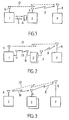
- Fig. 1 represents a first version of a mobile communication system block diagram; wherein 1 is a mobile communication means; 2 - a mobile repeater having one transceiver antenna 3 and a receiver 4 for receiving flux P of an auxiliary radiation 5 emitted by the.mobile communication means 1.
- the latter has a transceiver antenna 6 that produces electromagnetic radiation, whose carrier frequency presently is F1.
- Message transmissions in the mobile communication system are carried out by generating with the mobile communication means 1, e.g. a radio telephone, the electromagnetic radiation coded by this message, e.g.
- the mobile communication means 1 generating message-coded the auxiliary radiation 5, and at least one mobile repeater 2 is used, which repeater receives and processes the auxiliary radiation 5 and also generates and transmits said message-coded electromagnetic radiation.
- carrier frequency F1 is the frequency used for a given standard at this moment.
- carrier the frequency F1 can vary depending on location of the mobile communication means and a frequency channel within the operation frequency range wherein a message is transmitted. In other cases (CDMA standard), the frequency F1 can be changed continuously according to an arbitrary rule, density of distribution of probabilities of which rule having been determined in advance.
- flux P of auxiliary radiation 5 any radiations usually utilized for message transmission can be used: light, infrared, ultrasound and other radiations.
- a repeater is a transceiving radio station that receives signals, amplifies (converts) and transmits them farther.
- a relayed message will have the form of a sequence of bursts placed in special time slots.
- Such system will also comprise a base astation 7 with an antenna 8.
- a mobile means can be used instead of the base station 7 .
- the mobile repeater 2 is implemented as a portable device, located near a subscriber who has the mobile communication means 1, and intended to retransmit the flux P of the auxiliary radiation 5 on carrier the frequency F1.
- the process of transmission of electromagnetic radiation from the mobile repeater 2 is shown by a broken arrow 9.
- the message transmission from the mobile communication means 1 to the base station 7 is carried out directly by the mobile communication means 1 on carrier frequency of electromagnetic F1. Process of transmission of said radiation is shown by a dashed arrow 10.
- the mobile communication means 1 has an additional antenna 11.
- the system uses a plurality of the mobile repeaters 2, each of which repeaters has an additional antenna 12 to receive the auxiliary radiation 5.
- two separate transceiver antennas or one common transceiver antenna 3,6 (Fig. 3) can be used. In the latter case a duplex filter, i.e. a device separating the reception and transmission bands, can be used.
- Process of transmission of the electromagnetic auxiliary radiation from the communication means 1 to the mobile repeater 2 is shown by broken arrow 13.
- Process of transmission of the electromagnetic radiation to the communication means 1 from the mobile repeater 2 in the direction shown by broken arrow 13 is associated with transmission of control signals required for ascertaining a possibility of using the repeater 2.
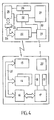
- Fig. 4 shows a functional diagram of a mobile radiotelephone (mobile communication means) 1 that is used in this system and consistent with the mobile repeater 2 in respect of its parameters.
- the mobile radio telephone comprises n(n>1) main transceivers 14 and at least one additional transceiver 15, an interface 16, a control unit (controller) 17 connected to an electromagnetic radiation presence indicator 18 and to an auxiliary radiation code inputting unit 19; and an internal power supply source 20.
- the indicator 18 one or more LED-emitters can be used.
- the main transceiver 14 provides transmission of the electromagnetic radiation having the frequency F1 and comprises a (controlled) radio circuit connected to a transceiver antenna.
- the additional transceiver 15 usually comprises the electronic circuits intended to be operated with auxiliary radiation emitters.
- the transceivers 14 and 15 can comprise common antenna 6.
- the transceivers 14, 15 are coupled via internal bus 21 through the interface 16 to the control unit 17 based on a microcomputer and including its conventional members: central processor, read-only and random-access memories, input-output means, timers, adapters, registers, analog-digital converters, etc. The latter are used, in particular, for measuring levels of the signal received by the mobile radiotelephone.
- Said circuitry usually includes one or more transceivers 22 connected through an interface 23 via internal bus 24 to a control unit (controller) 25 that in turn is connected to means 26 for establishing a unique code. It is noted that the control unit 25 can be provided therein with an indicator of operation modes of the mobile repeater 2. If the electromagnetic radiation is used as the auxiliary radiation, then the transceiver 22 comprises one or two antennas. One of these (receiving one) antennas can be implemented as a magnetic antenna.
- an internal power supply source 27 is connected to the repeater's electroniccircuitry via a means for activation of the mobile repeater 2 from the stand-by mode, which means includes controlled key 28; control input of said key being connected to a control circuit 29 that in turn is coupled to the transceiver 22.
- Dashed line 30 denotes connection of the power supply source 27 to the control circuit 29. This connection is required in the case when a separate power supply source is not used to energize the control unit 29.
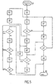
- Fig. 5 illustrates a chart of a system functioning algorithm. Reference numerals not completely designated in Fig. 5 are as follows.
- the device for transmitting a message in the mobile communication system is operated according to the logarithm chart shown in Fig. 5.
- step 31 is executed using an application software, which, first, is stored in a read-only memory in the control unit 17, and, second, - in memory of the controller 25 arranged in the mobile repeater 2.
- the algorithm is initiated (step 31) by turning-on of the mobile communication means 1. If such means is a radiotelephone, then step 31 is caused by "off-hook" instruction.
- step 32 After the mobile communication means 1 has been turned on, a signal for turning-on the mobile repeater 2 is generated and transmitted (step 32). Said signal can be transmitted by one of the transceivers 14, 15.
- the key 28 is released, and power from the source 27 is supplied to electronic circuitry of the mobile repeater 2.
- the control circuit 29 in the stand-by mode for turning the mobile repeater on is operated in the low current consumption mode from its own power supply source or from the source 27. Further, the step 32 describes how a code for ciphering the auxiliary radiation is established and selected.
- a ciphering (unique) code can be established manually or automatically. The manual establishing is done by setting the mutually consistent codes in the unit 19 and the means 26. Manual establishing can be done using special slide switches. Automatic establishing can be done in cases when the mobile communication means 1 seeks unoccupied channels according to the auxiliary radiation. In this case the algorithm of a unique code can be transferred to the controller 25 memory via channel 13.
- an efficient method for coding the auxiliary radiation is the use of a pseudonoise signal and the message transmission principles applied in a CDMA system.
- Automatic search for unoccupied channels according to the auxiliary radiation can be based on the principles used in mobile telephone communication systems.
- Checking of communication quality and also transmission of said parameters can be done by generation of a special signal in the mobile repeater 2, which signal either transmits the quality data of the signal received by the repeater from the mobile communication means via a channel that uses the auxiliary radiation, or this signal itself is the signal according to which the communication quality is assessed, but in this case in the mobile communication means proper.
- a cause of an unsatisfactory operation of a channel can also be indicated on the controller 17 display (poor condition of the power supply source 20, 27; presence of shielding objects between the means 1 and the repeater 2; external interference that affects the auxiliary radiation 5; maximal distance between the means 1 and the repeater 2 is exceeded).
- a message is transmitted (step 39) to the base station 7 via a channel that uses the flux P of the auxiliary radiation 5 and the electromagnetic radiation, coded by said message, having the frequency F1, which radiation is emitted by the antenna 3 of the mobile repeater 2 (Figs. 1, 2, 3).
- electromagnetic radiation of the frequency F2 is used as the auxiliary radiation 5
- message transmission will be carried out through the mobile repeater 2 that receives a signal on the frequency F2, demodulates, amplifies and transmits the same on the frequency F1 (Figs. 2, 3).
- the time taken to process a signal is considered as negligible.
- various types of mobile repeaters can be used.
- an "open repeater" When an "open repeater" is used, a signal is relayed when a carrier with a frequency corresponding to the repeater reception frequency appears in the air.
- relaying will occur only after an access programmed signal has been decoded.
- repeater In the simplest case, repeater can be enabled by relevant control signal. In case when more sophisticated controllers are used, an access code can be transmitted in various signalling systems.
- auxiliary radiation parameters are to be selected such so that they will not exert an injurious action on user's head.
- Such parameters obviously should be a very low the frequency F2 (F2 ⁇ F1) of radiation, or a very low level of radiation power. The author believes that the latter can be less than 1 mW. In such case the mobile telephone 1 can have no second transceiver 15. Then, electromagnetic radiation of the transceiver 2 having the frequency F1 (or a frequency approximating F1) with a lowered radiation power can be used as the auxiliary radiation.
- the instruction to reduce the radiation power in the transceiver 14 can be given to its control input from the control unit 17.
- the latter in its turn generates the instruction after, for example, the mobile telephone 1 has received a special signal from the mobile repeater 2.
- auxiliary frequency F2 must be slightly different from the average operation the frequency F1 of electromagnetic radiation.
- a change in the frequency F1 in this case can be carried out by a special instruction from the control unit 17 supplied to the main transceiver 14.
- step 40 Further operation of the system consists in assessing quality of radiation (in general case - quality of communication) on the frequency F1. After results of assessment of said quality (step 40) have been obtained, the radiation power is either increased or reduced to its rated value. In case of satisfactory ("Yes" in the condition 41) assessment of quality of communication on the channel 9 (Fig. 2, 3), power of the radiation emitted from the mobile repeater 2 can be changed.
- Rendering (step 42) of power of radiation having the frequency F1 after assessment of quality of this radio channel to its rated value is a standard operation applicable in many mobile communication systems (NMT, AMPS/DAMPS, GSM).
- the adjustment process used in a mobile communication system using NMT 450 standard can be described.
- radiation power is adjusted with a mobile switching center (MCS) that receives from base stations the signal/noise ratio assessment results.
- MCS mobile switching center
- MCS instructs mobile the communication means 1 to lower the radiated power level.
- Said power is received and decoded by the transceiver 14 and after its processing in the controller 17, the instruction to reduce the radiated power of the repeater 2 is generated, which instruction is delivered thereto via one of communication channels 13.
- the radiation power decrease instruction can be received by other repeater 22 and processed in the controller 25.
- the communication status on a channel is unsatisfactory ("No" in condition 41)
- its radiation power having average frequency F1 can be increased (step 43).
- its power can be increased by a change in a system setup by increasing (step 44) the number of simultaneously radiating the mobile repeaters 2.
- Such technique to increase power can be used in the case when a simple increase (step 43) of the radiation power having the frequency F1 only in one mobile repeater is not sufficient.
- the system setup (step 43) can be changed by disconnecting some communication means 1, 2 therefrom.
- Presence of a plurality of the mobile repeaters 2 causes additional inconveniences, because a subscriber is not able to attend to their presence in time of communication, by locating these repeaters at his place (car, case, office desk, etc.).
- a mobile repeater is arranged inside a means carried by a subscriber, then its control means (power switch, output power switch, etc.) and also indicators of its operation modes can be positioned at the exterior side of a means carried by a subscriber.
- step 46 In case after connection of additional mobile repeaters 2 communication quality still remains unsatisfactory ("No' in the condition 45), additional channel 10 (Figs. 2, 3) is connected automatically (step 46). After the mobile communication means 1 is disabled ("Yes" in the condition 47), the mobile repeater 2 is brought automatically to the stand-by mode to wait for activation (step 48).
- the simplest way to execute this step can be generation of a relevant signal by the controller 25 after, first, auxiliary radiation 5 has disappeared; and, second, after a certain time period has elapsed. This measure is required to exclude false transition of the mobile repeater 2 into the stand-by mode subsequent to a brief inadvertent loss of the auxiliary radiation.
- some mobile communication means can include the following additional functions or elements: a mobile repeater (to determine location of the mobile repeater) provides audible and light signals when a corresponding key is pressed on a mobile communication means or when the call signal is provided from the mobile communication means; indication of the direction towards the mobile repeater location on a mobile communication means; a mobile repeater is internally equipped with directed the antennas 3, 12 and with a system for orienting them in the optimal direction; audible message to a mobile communication means subscriber about status of a mobile repeater (battery discharge alarm, mobile repeater location signalling).
- the invention can be suitably used in such communication fields as mobile telephone communication of all known standards (GSM, TDMA, JDC, CDMA, etc.), IRIDIUM and GLOBALSTAR global satellite personal mobile communication; trunking radiotelephone communication system; personal wireless communication radio stations.
- This invention can be further used with such communication means as wireless telephones.
- the direct or reflected-from-premises-objects light or infrared radiation can be used as the auxiliary radiation to establish communication from a wireless handset to a base unit.
- the information outputted from the base unit and inputted into wireless handset that should be transmitted by the auxiliary radiation it is the information outputted from the base unit and inputted into wireless handset that should be transmitted by the auxiliary radiation.
- This invention can find its wide use also in the public places with presence of persons using a mobile telephone communication. In this case, such places are pre-provided with multichannel mobile repeaters, each comprising, for example, a number of transceivers, and thus said repeaters become fixed ones.
Landscapes
- Engineering & Computer Science (AREA)
- Computer Networks & Wireless Communication (AREA)
- Signal Processing (AREA)
- Mobile Radio Communication Systems (AREA)
- Radio Relay Systems (AREA)
- Variable-Direction Aerials And Aerial Arrays (AREA)
Claims (3)
- Verfahren zum Übertragen einer Nachricht in einem mobilen Kommunikationssystem, umfassend eine erste mobile Kommunikationseinrichtung (1), einen mobilen Repeater (2) und eine zweite Kommunikationseinrichtung (7), gekennzeichnet durch folgende Schritte:im mobilen Repeater (2), Bewerten (33) der Signalqualität einer von der ersten mobilen Kommunikationeinrichtung (1) empfangenen Nachricht;Setzen (34) eines Schwellenwertes für den Signalpegel der empfangenen Nachricht, wobei die erste mobile Kommunikationseinrichtung (1) für den Fall, dass der Signalpegel der empfangenen Nachricht schlechter ist als der Schwellenwert, Daten, unter Verwendung eines ersten Transceivers (14), der eine nachrichten-modulierte elektromagnetische Strahlung (10) aussendet, direkt zu der zweiten Kommunikationseinrichtung (7) überträgt, und die erste mobile Kommunikationseinrichtung (1) für den Fall, dass der Signalpegel der empfangenen Nachricht besser ist als ein vorgegebener Schwellenwert, Daten über den mobilen Repeater (2) unter Verwendung eines zweiten Transceivers (15), der eine nachrichten- modulierte Hilfsstrahlung (5) aussendet, und eines im mobilen Repeater (2) enthaltenen Transmitters (22), der eine nachrichten-modulierte elektromagnetische Strahlung (9) aussendet, zu der zweiten Kommunikationseinrichtung (7) überträgt.
- Verfahren nach Anspruch 1, dadurch gekennzeichnet, dass eine Infrarotstrahlung (5) als die nachrichten-modulierte Hilfsstrahlung verwendet wird.
- Verfahren nach Anspruch 1 oder 2, dadurch gekennzeichnet, dass ein Mobiltelefon als die erste mobile Kommunikationseinrichtung (1) verwendet wird, wobei eine Anzeigeeinrichtung des Telefons einen Batteriezustand (27) des mobilen Repeaters (2) anzeigt.
Applications Claiming Priority (3)
| Application Number | Priority Date | Filing Date | Title |
|---|---|---|---|
| RU98117651/09A RU98117651A (ru) | 1998-09-21 | Способ и устройство передачи сообщения в мобильной системе связи | |
| RU98117651 | 1998-09-21 | ||
| PCT/RU1999/000341 WO2000018040A1 (en) | 1998-09-21 | 1999-09-20 | Method and device for transmitting a message in a mobile communication system |
Publications (3)
| Publication Number | Publication Date |
|---|---|
| EP1143641A1 EP1143641A1 (de) | 2001-10-10 |
| EP1143641A4 EP1143641A4 (de) | 2005-08-10 |
| EP1143641B1 true EP1143641B1 (de) | 2008-01-09 |
Family
ID=20210709
Family Applications (1)
| Application Number | Title | Priority Date | Filing Date |
|---|---|---|---|
| EP99969554A Expired - Lifetime EP1143641B1 (de) | 1998-09-21 | 1999-09-20 | Verfahren und gerät zur übertragung einer nachricht in einem mobilen kommunikationssystem |
Country Status (5)
| Country | Link |
|---|---|
| EP (1) | EP1143641B1 (de) |
| AU (1) | AU6012799A (de) |
| DE (1) | DE69937969T2 (de) |
| EA (1) | EA002912B1 (de) |
| WO (1) | WO2000018040A1 (de) |
Families Citing this family (9)
| Publication number | Priority date | Publication date | Assignee | Title |
|---|---|---|---|---|
| DE50011383D1 (de) * | 2000-08-09 | 2006-03-02 | Ericsson Telefon Ab L M | Verfahren zur bereichsabhängigen Betriebsparametereinstellung bei einem mobilen Endgerät, zugehöriges Endgerät und Bereichsinformationssender |
| RU2206959C2 (ru) * | 2001-09-12 | 2003-06-20 | Общество С Ограниченной Ответственностью "Сивера" | Способ и устройство передачи сообщения в мобильной системе связи |
| KR20040039560A (ko) * | 2002-11-02 | 2004-05-12 | 엘지전자 주식회사 | 이동 통신 단말기의 안테나에 장착되는 휴대용 중계기 |
| GB2405290B (en) * | 2003-08-21 | 2006-04-26 | Motorola Inc | Wireless communication system and wireless communication repeater for use therein |
| GB2426665B (en) * | 2005-05-25 | 2009-12-02 | Samsung Electronics Co Ltd | Mobile relays |
| JP5685418B2 (ja) * | 2010-11-10 | 2015-03-18 | ホーチキ株式会社 | 無線中継器 |
| EA201400631A1 (ru) * | 2012-08-29 | 2014-11-28 | Валерий Филиппович ИВАНОВ | Способ мобильной связи с использованием подвижного ретранслятора |
| EP3300264B1 (de) * | 2013-06-25 | 2021-02-24 | Andrew Wireless Systems GmbH | Verstärkersystem |
| RU2720351C1 (ru) * | 2019-06-05 | 2020-04-29 | Общество с ограниченной ответственностью "ДиС ПЛЮС" | Устройство мобильной связи, подвижной ретранслятор и способ их использования |
Family Cites Families (10)
| Publication number | Priority date | Publication date | Assignee | Title |
|---|---|---|---|---|
| US4539706A (en) * | 1983-02-03 | 1985-09-03 | General Electric Company | Mobile vehicular repeater system which provides up-link acknowledgement signal to portable transceiver at end of transceiver transmission |
| SU1522417A1 (ru) * | 1987-10-09 | 1989-11-15 | Предприятие П/Я Р-6120 | Система св зи с ретрансл цией сообщений |
| SU1555881A1 (ru) * | 1988-04-22 | 1990-04-07 | Московский энергетический институт | Устройство св зи наземных станций |
| JPH04372234A (ja) * | 1991-06-21 | 1992-12-25 | Fujitsu Ltd | 送信電力制御方式 |
| JPH0530000A (ja) * | 1991-07-18 | 1993-02-05 | Fujitsu Ltd | 移動体通信方式 |
| JPH06276146A (ja) * | 1993-03-19 | 1994-09-30 | Fujitsu Ltd | 移動電話装置 |
| DE4337244A1 (de) * | 1993-10-30 | 1995-05-04 | Sel Alcatel Ag | Mobilfunksystem mit einem Zwischenverstärker |
| EP0688139A3 (de) * | 1994-06-16 | 1998-12-16 | Ascom Business Systems Ag | Vorrichtung zum Erhöhen des Funktionsbereiches eines Systems digital arbeitender Schnurlostelefone |
| JP2842267B2 (ja) * | 1994-12-30 | 1998-12-24 | 日本電気株式会社 | 携帯無線機 |
| DE19600119C2 (de) * | 1996-01-04 | 1997-11-20 | Dirk Wuelfing | Tragbares Teilnehmerendgerät für den Mobilfunk |
-
1999
- 1999-09-20 EP EP99969554A patent/EP1143641B1/de not_active Expired - Lifetime
- 1999-09-20 AU AU60127/99A patent/AU6012799A/en not_active Abandoned
- 1999-09-20 WO PCT/RU1999/000341 patent/WO2000018040A1/ru not_active Ceased
- 1999-09-20 EA EA200100380A patent/EA002912B1/ru not_active IP Right Cessation
- 1999-09-20 DE DE69937969T patent/DE69937969T2/de not_active Expired - Fee Related
Also Published As
| Publication number | Publication date |
|---|---|
| EP1143641A1 (de) | 2001-10-10 |
| WO2000018040A1 (en) | 2000-03-30 |
| EP1143641A4 (de) | 2005-08-10 |
| EA200100380A1 (ru) | 2001-08-27 |
| DE69937969D1 (de) | 2008-02-21 |
| DE69937969T2 (de) | 2009-01-08 |
| EA002912B1 (ru) | 2002-10-31 |
| AU6012799A (en) | 2000-04-10 |
Similar Documents
| Publication | Publication Date | Title |
|---|---|---|
| EP1437899B1 (de) | Verfahren und einrichtung zum übertragen von informationen im mobilkommunikationsmodus | |
| ES2402737T3 (es) | Repetidor y procedimiento para la operación de un repetidor de este tipo | |
| US6393254B1 (en) | Disabler for mobile communications | |
| US5991614A (en) | Utilization management system of portable telephone | |
| EP1122897A1 (de) | Gerät und anordnung zum verhindern eines telefonrufs | |
| US20090146791A1 (en) | Method, device, and system for "listen-before-talk" measurement to enable identifying of one or more unoccupied RF sub-bands | |
| WO1998007286A2 (en) | In-band vehicular repeater for trunked radio system | |
| EP0943184B1 (de) | Mobiles kommunikationsgerät und sender zum kommunizieren mit dem mobilen kommunikationsgerät | |
| WO1998056192A2 (en) | Cellular communications firewall | |
| EP1143641A1 (de) | Verfahren und gerät zur übertragung einer nachricht in einem mobilen kommunikationssystem | |
| US6745037B1 (en) | Method of protecting a limited local area against electromagnetic radiation emitted by mobile radio terminals, radio station and mobile radio terminal | |
| CA2055459C (en) | Trunking method and apparatus for establishing communication in a two-way mobile radio system | |
| JP3625261B2 (ja) | 移動局機能規制システム及びそのシステムで用いられる移動局、基地局及び規制装置 | |
| CA2473129C (en) | Scanning tone remote adapter for land-mobile radio dispatch for use with dispersed dispatch stations | |
| CN207251924U (zh) | 一种上下行链路不平衡的自适应系统 | |
| GB2242337A (en) | Base stations for mobile telephones | |
| RU2351074C2 (ru) | Региональная сеть мобильной связи и абонентский терминал | |
| CZ102599A3 (cs) | Způsob bezdrátového přenosu lokalizačních a užitečných informací a vysílací/ přijímací zařízení | |
| US5550832A (en) | Time division multiple access radio transmission activated receiver switch | |
| KR100664132B1 (ko) | 이동통신 단말기의 자외선지수 전송 방법 | |
| Flintoft et al. | Radio-Frequency Exposure Assessment for Emerging Technologies | |
| KR840005948A (ko) | 대인 호출용 전자식 전화시스템 | |
| JP2004096276A (ja) | 移動局周辺の電界強度制御機能を持つ中継局を含む移動体通信システム | |
| JPH08251648A (ja) | 特定小電力無線システムの発呼先自動認識通信装置 | |
| MXPA06011578A (en) | Satellite/hands-free interlock systems and/or companion devices for radioterminals and related methods |
Legal Events
| Date | Code | Title | Description |
|---|---|---|---|
| PUAI | Public reference made under article 153(3) epc to a published international application that has entered the european phase |
Free format text: ORIGINAL CODE: 0009012 |
|
| 17P | Request for examination filed |
Effective date: 20010420 |
|
| AK | Designated contracting states |
Kind code of ref document: A1 Designated state(s): AT BE CH CY DE DK ES FI FR GB GR IE IT LI LU MC NL PT SE Kind code of ref document: A1 Designated state(s): DE FI FR NL SE |
|
| AX | Request for extension of the european patent |
Free format text: AL;LT;LV;MK;RO;SI |
|
| RAP1 | Party data changed (applicant data changed or rights of an application transferred) |
Owner name: OBSCHESTVO S ORGANICHENNOI OTVETSTVENNOSTIJU "SIVE |
|
| RIN1 | Information on inventor provided before grant (corrected) |
Inventor name: OBSCHESTVO S ORGANICHENNOI OTVETSTVENNOSTIJU "SIVE |
|
| RBV | Designated contracting states (corrected) |
Designated state(s): DE FI FR NL SE |
|
| A4 | Supplementary search report drawn up and despatched |
Effective date: 20050623 |
|
| RIC1 | Information provided on ipc code assigned before grant |
Ipc: 7H 04Q 7/32 B Ipc: 7H 04B 1/38 B Ipc: 7H 04B 7/005 B Ipc: 7H 04B 7/15 B Ipc: 7H 04B 7/26 A |
|
| 17Q | First examination report despatched |
Effective date: 20060131 |
|
| 17Q | First examination report despatched |
Effective date: 20060131 |
|
| GRAP | Despatch of communication of intention to grant a patent |
Free format text: ORIGINAL CODE: EPIDOSNIGR1 |
|
| GRAS | Grant fee paid |
Free format text: ORIGINAL CODE: EPIDOSNIGR3 |
|
| GRAA | (expected) grant |
Free format text: ORIGINAL CODE: 0009210 |
|
| AK | Designated contracting states |
Kind code of ref document: B1 Designated state(s): DE FI FR NL SE |
|
| REF | Corresponds to: |
Ref document number: 69937969 Country of ref document: DE Date of ref document: 20080221 Kind code of ref document: P |
|
| REG | Reference to a national code |
Ref country code: SE Ref legal event code: TRGR |
|
| ET | Fr: translation filed | ||
| PLBE | No opposition filed within time limit |
Free format text: ORIGINAL CODE: 0009261 |
|
| STAA | Information on the status of an ep patent application or granted ep patent |
Free format text: STATUS: NO OPPOSITION FILED WITHIN TIME LIMIT |
|
| PGFP | Annual fee paid to national office [announced via postgrant information from national office to epo] |
Ref country code: NL Payment date: 20080926 Year of fee payment: 10 Ref country code: FI Payment date: 20080924 Year of fee payment: 10 |
|
| 26N | No opposition filed |
Effective date: 20081010 |
|
| PGFP | Annual fee paid to national office [announced via postgrant information from national office to epo] |
Ref country code: DE Payment date: 20080929 Year of fee payment: 10 |
|
| PGFP | Annual fee paid to national office [announced via postgrant information from national office to epo] |
Ref country code: SE Payment date: 20080924 Year of fee payment: 10 |
|
| PGFP | Annual fee paid to national office [announced via postgrant information from national office to epo] |
Ref country code: FR Payment date: 20080924 Year of fee payment: 10 |
|
| REG | Reference to a national code |
Ref country code: NL Ref legal event code: V1 Effective date: 20100401 |
|
| PG25 | Lapsed in a contracting state [announced via postgrant information from national office to epo] |
Ref country code: FI Free format text: LAPSE BECAUSE OF NON-PAYMENT OF DUE FEES Effective date: 20090920 |
|
| EUG | Se: european patent has lapsed | ||
| REG | Reference to a national code |
Ref country code: FR Ref legal event code: ST Effective date: 20100531 |
|
| PG25 | Lapsed in a contracting state [announced via postgrant information from national office to epo] |
Ref country code: NL Free format text: LAPSE BECAUSE OF NON-PAYMENT OF DUE FEES Effective date: 20100401 Ref country code: FR Free format text: LAPSE BECAUSE OF NON-PAYMENT OF DUE FEES Effective date: 20090930 Ref country code: DE Free format text: LAPSE BECAUSE OF NON-PAYMENT OF DUE FEES Effective date: 20100401 |
|
| PG25 | Lapsed in a contracting state [announced via postgrant information from national office to epo] |
Ref country code: SE Free format text: LAPSE BECAUSE OF NON-PAYMENT OF DUE FEES Effective date: 20090921 |