EP1143258A2 - Compensation pour la dérive du champ magnétique dans l'IRM - Google Patents
Compensation pour la dérive du champ magnétique dans l'IRM Download PDFInfo
- Publication number
- EP1143258A2 EP1143258A2 EP01303312A EP01303312A EP1143258A2 EP 1143258 A2 EP1143258 A2 EP 1143258A2 EP 01303312 A EP01303312 A EP 01303312A EP 01303312 A EP01303312 A EP 01303312A EP 1143258 A2 EP1143258 A2 EP 1143258A2
- Authority
- EP
- European Patent Office
- Prior art keywords
- magnetic field
- compensation
- data acquisition
- field drift
- pulse sequences
- Prior art date
- Legal status (The legal status is an assumption and is not a legal conclusion. Google has not performed a legal analysis and makes no representation as to the accuracy of the status listed.)
- Ceased
Links
Images


Classifications
-
- A—HUMAN NECESSITIES
- A61—MEDICAL OR VETERINARY SCIENCE; HYGIENE
- A61B—DIAGNOSIS; SURGERY; IDENTIFICATION
- A61B5/00—Measuring for diagnostic purposes; Identification of persons
- A61B5/05—Detecting, measuring or recording for diagnosis by means of electric currents or magnetic fields; Measuring using microwaves or radio waves
-
- G—PHYSICS
- G01—MEASURING; TESTING
- G01R—MEASURING ELECTRIC VARIABLES; MEASURING MAGNETIC VARIABLES
- G01R33/00—Arrangements or instruments for measuring magnetic variables
- G01R33/20—Arrangements or instruments for measuring magnetic variables involving magnetic resonance
- G01R33/44—Arrangements or instruments for measuring magnetic variables involving magnetic resonance using nuclear magnetic resonance [NMR]
- G01R33/48—NMR imaging systems
- G01R33/54—Signal processing systems, e.g. using pulse sequences ; Generation or control of pulse sequences; Operator console
- G01R33/56—Image enhancement or correction, e.g. subtraction or averaging techniques, e.g. improvement of signal-to-noise ratio and resolution
- G01R33/565—Correction of image distortions, e.g. due to magnetic field inhomogeneities
- G01R33/56563—Correction of image distortions, e.g. due to magnetic field inhomogeneities caused by a distortion of the main magnetic field B0, e.g. temporal variation of the magnitude or spatial inhomogeneity of B0
Definitions
- the present invention relates to a data acquisition method of compensation for magnetic field drift, a method of compensation for magnetic field drift, and an MRI (magnetic resonance imaging) apparatus, and more particularly to a data acquisition method of compensation for magnetic field drift, a method of compensation for magnetic field drift, and an MRI apparatus, allowing improvement of the image quality by compensating for the magnetic field drift and reduction of overall scanning time.
- magnetic field drift compensation will be compensated for by measuring the magnetic field drift during gathering data for imaging. This technique allows compensation to be improved more accurately than gathering independent data for magnetic field drift compensation separated apart from data gathered for imaging.
- the repetition time TR becomes longer, because the repetitive unity of pulse sequences includes a pulse sequence for gathering the imaging data, plus a pulse sequence for gathering data for compensation for magnetic field drift.
- the scanning time as whole will be longer.
- the object of the present invention is to provide a data acquisition method for magnetic field drift compensation, a method of magnetic field drift compensation, and an MRI apparatus, allowing improvement of the image quality by compensating for the magnetic field drift and reduction of overall scanning time.
- a data acquisition method of magnetic field drift compensation is provided, characterized by N > M ⁇ 2, where: N is the number of repetition of pulse sequences for gathering imaging data, M is the total number of repetition of pulse sequences for gathering data for magnetic field compensation; and acquiring data for magnetic field compensation by interposing at least one or more pulse sequences for gathering data for magnetic field drift compensation between two pulse sequences for gathering imaging data.
- the total number of pulse sequences for gathering data for magnetic field drift compensation, M will be smaller than the repetition of pulse sequences for gathering imaging data, N, and a pulse sequence for gathering data for magnetic field drift compensation will be inserted between pulse sequences for gathering imaging data.
- N 256
- M 128, one pulse sequence for gathering data for magnetic field drift compensation will be inserted between two pulse sequences for gathering imaging data.
- overall scanning time required may be shorter than adding a pulse sequence for gathering compensation data for magnetic field drift to each pulse sequence for gathering imaging data.
- a method in the data acquisition method of magnetic field drift compensation of the arrangement described above, characterized in that the integral of gradient field in the imaging data acquisition pulse sequence will be equal to the integral of gradient field in the pulse sequence for data acquisition of compensation for drift in magnetic field, for each of axis in order to hold the steady state of spins.
- the integration of gradient field in the imaging data acquisition pulse sequence will be equal to the integration of gradient field in the pulse sequence for data acquisition of compensation for drift in magnetic field, such that the gradient field of the pulse sequences for data acquisition of compensation for drift in magnetic field, when inserted between the imaging data acquisition pulse sequences, will not affect to the imaging data acquisition pulse sequence.
- a method in the data acquisition method of magnetic field drift compensation of the arrangement described above, characterized in that the imaging data acquisition pulse sequences are pulse sequences of the gradient echo method having read gradient for convergence of gradient echo, and the data acquisition pulse sequences of magnetic field drift compensation are pulse sequences without read gradient and phased gradient for convergence of gradient echo during imaging data acquisition pulse sequences.
- compensation data for magnetic field drift can be acquired, in a manner preferable to the imaging data acquisition by pulse sequences of the gradient echo method.
- a method in the data acquisition method of magnetic field drift compensation of the arrangement described above, characterized in that the pulse sequences for acquiring imaging data are pulse sequences by the spin echo method having diffused read gradient between a 90 ° RF pulse and a 180 ° RF pulse, and the pulse sequences for acquiring compensation data for magnetic field drift are pulse sequences without diffuse read gradient in the imaging data acquisition pulse sequences, and corresponding read gradient and phase gradient after 180 ° RF pulses.
- compensation data for magnetic field drift can be acquired, in a manner preferable to the acquisition of imaging data by the pulse sequences of the spinning echo method.
- a method in the data acquisition method of magnetic field drift compensation of the arrangement described above, a method is provided, characterized in that the pulse sequences for acquiring imaging data are pulse sequences of high-speed spinning echo method, having diffuse read gradient between a 90 ° RF pulse and a 180 ° RF pulse, and between a 180 ° RF pulse and another 180 ° RF pulse, the pulse sequences for acquiring magnetic field drift compensation data are pulse sequences without diffuse read gradient in the imaging data acquisition pulse sequence, and corresponding read gradient and phase gradient after a 180 ° RF pulse.
- compensation data for magnetic field drift can be acquired, in a manner preferable to the imaging data acquisition by pulse sequences of the high-speed spinning echo method (the multi-echo method also).
- a method is provided, characterized by the step of adjusting the current of primary field coil based on the compensation data for magnetic field drift gathered in accordance with the data acquisition method of magnetic field drift of the arrangement described above.
- the current flowing through the primary field coil is adjusted so as to compensate for the magnetic field drift to improve the image quality.
- a method of compensation for magnetic field drift characterized by the step of adjusting the transmission frequency based on the compensation data for magnetic field drift gathered in accordance with the data acquisition method of compensation for magnetic field drift of the arrangement as described above.
- the transmission frequency is adjusted so as to compensate for magnetic field drift to improve the image quality.
- a method of compensation for magnetic field drift characterized by the step of adjusting the transmission frequency and reception frequency based on the compensation data for magnetic field drift gathered in accordance with the data acquisition method of compensation for magnetic field drift of the arrangement as have been described above.
- the transmission frequency and reception frequency are adjusted so as to compensating for magnetic field drift to improve the image quality.
- a method of compensation for magnetic field drift characterized by the step of adjusting the phase of transmission or the phase of reception based on the compensation data for magnetic field drift gathered in accordance with the data acquisition method of compensation for magnetic field drift of the arrangement as have been described above.
- either the phase of transmission or the phase of reception may be adjusted so as to compensate for magnetic field drift to improve the image quality.
- a method of compensation for magnetic field drift characterized by the step of carrying out phase compensating operation on the imaging data, based on the compensation data for magnetic field drift gathered by the data acquisition method of compensation for magnetic field drift of the arrangement as have been described above.
- the phase compensating operation will be performed on the imaging data so as to compensate for magnetic field drift to improve the image quality.
- an MRI apparatus characterized by comprising: an RF pulse transmitter means, a gradient pulse applicator means, an NMR signal receiver means, a means for controlling imaging data acquisition for acquiring imaging data by controlling each of the means, and a means for controlling compensation data acquisition for magnetic field drift for acquiring magnetic field drift compensation data by controlling each of the means, wherein the means for controlling compensation data acquisition for magnetic field drift is characterized by N > M ⁇ 2, where: N is the number of repetition of pulse sequences for gathering imaging data, M is the total number of repetition of pulse sequences for gathering data for magnetic field compensation; and acquiring data for magnetic field compensation by interposing at least one or more pulse sequences for gathering data for magnetic field drift compensation between two pulse sequences for gathering imaging data.
- the data acquisition method for compensating for magnetic field drift in accordance with the aforementioned first aspect of the present invention may be preferably implemented.
- an MRI apparatus characterized in that in the means for controlling compensation data acquisition for magnetic field drift in the MRI apparatus of the arrangement as above, the integration of gradient field in the imaging data acquisition pulse sequence may be equal to the integration of gradient field in the pulse sequence for data acquisition of compensation for drift in magnetic field.
- an MRI apparatus characterized in that in the MRI apparatus of the arrangement as have been described above, the imaging data acquisition pulse sequences may be pulse sequences of the gradient echo method having read gradient for convergence of gradient echo, and the data acquisition pulse sequences of magnetic field drift compensation may be pulse sequences without read gradient and phased gradient for convergence of gradient echo during imaging data acquisition pulse sequences.
- an MRI apparatus characterized in that in the MRI apparatus of the arrangement as have been described above, the pulse sequences for acquiring imaging data are pulse sequences by the spin echo method having diffused read gradient between a 90 ° RF pulse and a 180 ° RF pulse, and the pulse sequences for acquiring compensation data for magnetic field drift are pulse sequences without diffuse read gradient in the imaging data acquisition pulse sequences, and corresponding read gradient and phase gradient after 180 ° RF pulses.
- an MRI apparatus characterized in that, in the MRI apparatus of the arrangement as have been described above, the pulse sequences for acquiring imaging data are pulse sequences of high-speed spinning echo method, having diffuse read gradient between a 90 ° RF pulse and a 180 ° RF pulse, and between a 180 ° RF pulse and another 180 ° RF pulse, the pulse sequences for acquiring magnetic field drift compensation data are pulse sequences without diffuse read gradient in the imaging data acquisition pulse sequence, and corresponding read gradient and phase gradient after a 180 ° RF pulse.
- the data acquisition method of the fifth aspect for compensating for magnetic field drift may be preferably implemented.
- an MRI apparatus characterized in that it further comprises a means for controlling the current of primary field coil based on the compensation data for magnetic field drift gathered by the means for controlling compensation data acquisition for magnetic field drift, in the MRI apparatus of the arrangement as have been described above.
- the compensation method for magnetic field drift in accordance with the sixth aspect mentioned above may be preferably implemented.
- an MRI apparatus characterized in that it further comprises a means for controlling excitation frequency for controlling the transmission frequency based on the compensation data for magnetic field drift gathered by the means for controlling compensation data acquisition for magnetic field drift, in the MRI apparatus of the arrangement as have been described above.
- the compensation method of magnetic field drift in accordance with the seventh aspect mentioned above may be preferably implemented.
- an MRI apparatus characterized in that it further comprises a means for controlling resonance frequency for controlling the transmission frequency and reception frequency based on the compensation data for magnetic field drift gathered by the means for controlling compensation data acquisition for magnetic field drift as mentioned above.
- the compensation method of magnetic field drift in accordance with the eighth aspect of the present invention may be preferably implemented.
- an MRI apparatus characterized in that it further comprises a phase controller means for controlling the transmission phase or reception phase based on the compensation data for magnetic field drift gathered by the means for controlling compensation data acquisition for magnetic field drift in the MRI apparatus of the arrangement as mentioned above.
- the compensation method of magnetic field drift in accordance with the ninth aspect of the present invention as mentioned above may be preferably implemented.
- a method for compensating for magnetic field drift characterized in that it further comprises a means for operating phase compensation for performing the operation of phase compensation on the imaging data based on the compensation data for magnetic field drift gathered by the means for controlling compensation data acquisition for magnetic field drift in the MRI apparatus of the arrangement as aforementioned above.
- the compensation method for magnetic field drift of the tenth aspect as have been described above may be preferably implemented.
- the method disclosed of acquiring compensation data for magnetic field drift, compensation method of magnetic field drift, and MRI apparatus may measure and compensate for the magnetic field drift during imaging data acquisition, allowing the precision of compensation to be improved.
- the overall scanning time may be shortened since total number of pulse sequences for compensation data acquisition for magnetic field drift may be fewer than the repetitive number of imaging data acquisition pulse sequences.
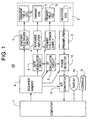
- FIG. 1 is a schematic block diagram of an MRI apparatus 100 in accordance with one preferred embodiment of the invention.
- a magnet assembly 1 has a central lumen (bore) for inserting the subject to be examined therein, and the assembly also has a primary field coil 1p for applying primary magnetic field of constant strength to the subject, a gradient field coil 1g for generating gradient field in the slice axis, read axis, and phase axis, a transmitter coil 1t for applying RF pulses for exciting atomic spins within the subject, and a receiver coil 1r for detecting NMR signals originated from the subject, surrounding the bore.
- the primary field coil 1p, gradient field coil 1g, transmitter coil 1t, and receiver coil 1r are connected respectively to a primary field power supply 2, a gradient field driver circuit 3, an RF power amplifier 4, and a preamplifier 5.
- Permanent magnets may be used in place of the primary field coil 1p.
- a sequence memory 6 drives the gradient field driver circuit 3 based on the pulse sequence stored therein under the instruction from a computer 7 to cause the gradient field coil 1g of the magnet assembly 1 to generate gradient field.
- the sequence memory 6 also drives a gate modulator circuit 8 to modulate the carrier output signal of an RF oscillator circuit 9 into pulse signals with a predetermined form of envelopes and predetermined timings to apply it as RF pulses to the RF power amplifier 4.
- the RF pulses will be power amplified in the RF power amplifier 4, applied to the transmitter coil 1t of the magnet assembly 1 to selectively excite a desired slice area.
- the preamplifier 5 will amplify the NMR signals from the subject detected by the receiver coil 1r of the magnet assembly 1 prior to input to a phase detector 10.
- the phase detector 10 will phase detect the NMR signals via the preamplifier 5 by referring to the carrier output signals generated by the RF oscillator circuit 9 and then pass the signal to an A/D converter 11.
- the A/D converter 11 will analog-to-digital convert the phase detected analog signals into digital signals to be fed to the computer 7.
- the computer 7 will read data from the A/D converter 11 to operate for image reconstruction thereon to generate an image of the desired slice area. This image will be displayed on a display 13. The computer 7 will also control the entire system such as accepting information input from a console 12.
- Fig. 2 is a flow diagram illustrating the data acquisition in the MRI apparatus 100.
- N is the number of repetition of pulse sequences for gathering imaging data
- M is the total number of repetition of pulse sequences for gathering data for magnetic field compensation.
- imaging data acquisition counter I will be cleared to be initialized to '1'.
- step S2 compensation data acquisition counter for magnetic field drift D will be cleared to be initialized to '1'.
- step S3 'I'th imaging data will be gathered by using imaging data acquisition pulse sequences.
- step S5 'D'th compensation data for magnetic field drift will be gathered by using the pulse sequences of compensation data acquisition for magnetic field drift.
- step S6 the compensation data acquisition counter for magnetic field drift D will be incremented by '1', and the process proceeds to step S7.
- step S8 the imaging data acquisition counter I will be incremented by '1' and the process goes back to the step S3.
- Fig. 3 is an exemplary pulse sequences in the data acquisition process as have been described above.
- pulse sequences of gradient echo mode will be used for the imaging data acquisition pulse sequences Im.
- pulse sequences of data acquisition for magnetic field drift compensation Md are without read gradient (leading halfway of 'rd' and 'rr') for converging the gradient echoes (echo 1, echo 2) in the imaging data acquisition pulse sequences Im, and phase gradient ('pe' and 'pr'). Compensation data for magnetic field drift can be acquired from within FID signals.
- the integral of gradient field ('rd', 'rr') in the imaging data acquisition pulse sequences Im will be equal to the integral of gradient field ('rh') of the pulse sequences of data acquisition for magnetic field drift compensation Md.
- no gradient field is applied to the phase axis in the pulse sequences of data acquisition for magnetic field drift compensation Md, because the integral of gradient field ('pe', 'pr') in the imaging data acquisition pulse sequences Im becomes '0'.
- Fig. 4 is another example of pulse sequences in the data acquisition process as have been described above.
- spinning echo mode pulse sequences are used for the imaging data acquisition pulse sequences Im.
- pulse sequences of data acquisition for magnetic field drift compensation Md are without the diffuse read gradient ('rd') between a 90 ° RF pulse R and a 180 ° RF pulse P in the imaging data acquisition pulse sequences Im, and the read gradient (leading half of 'rr') and phase gradient ('pe') corresponding thereto after the 180 ° RF pulse P.
- Data for magnetic field drift compensation can be acquired from within the spin_echo signals.
- Fig. 5 is still another example of pulse sequences in the data acquisition process as have been described above.
- pulse sequences of high-speed spin echo mode are used for the imaging data acquisition pulse sequences Im.
- diffuse read gradient (trailing half of 'rd' and 'rr') between a 90 ° pulse R and a 180 ° RF pulse P and between a 180 ° pulse P and another 180 ° pulse P in the imaging data acquisition pulse sequences Im, as well as the read gradient (leading half of 'rr') and phase gradient ('pe') corresponding thereto after the 180 ° RF pulse P.
- Data for magnetic field drift compensation can be acquired from within the first spin_echo signal.
- the integral of gradient field ('rd', 'rr') in the imaging data acquisition pulse sequences Im will be equal to the integral of gradient field ('rh') of the pulse sequences of data acquisition for magnetic field drift compensation Md.
- no gradient field is applied to the phase axis in the pulse sequences of data acquisition for magnetic field drift compensation Md, because the integral of gradient field ('pe', 'pr') in the imaging data acquisition pulse sequences Im becomes '0'.
- pulse sequences When applying slice encoding to the slice axis in the pulse sequences shown in Fig. 5, pulse sequences will be 3D.
- the aforementioned MRI apparatus 100 may compensate magnetic field drift after acquiring compensation data for magnetic field drift during the data acquisition process described above, in either of the followings:
- magnetic field drift may be measured and compensated for during acquisition of imaging data, allowing the compensation to be more accurate than the compensation by separate and independent acquisition of compensation data for magnetic field drift apart from the imaging data. Furthermore, overall scanning time may be shortened when comparing with the addition of a pulse sequence for compensation data for magnetic field drift for each imaging data acquisition pulse sequence.
Landscapes
- Physics & Mathematics (AREA)
- Health & Medical Sciences (AREA)
- Life Sciences & Earth Sciences (AREA)
- General Health & Medical Sciences (AREA)
- Nuclear Medicine, Radiotherapy & Molecular Imaging (AREA)
- Radiology & Medical Imaging (AREA)
- Engineering & Computer Science (AREA)
- Signal Processing (AREA)
- Condensed Matter Physics & Semiconductors (AREA)
- General Physics & Mathematics (AREA)
- High Energy & Nuclear Physics (AREA)
- Heart & Thoracic Surgery (AREA)
- Pathology (AREA)
- Biomedical Technology (AREA)
- Biophysics (AREA)
- Medical Informatics (AREA)
- Molecular Biology (AREA)
- Surgery (AREA)
- Animal Behavior & Ethology (AREA)
- Public Health (AREA)
- Veterinary Medicine (AREA)
- Magnetic Resonance Imaging Apparatus (AREA)
Applications Claiming Priority (2)
| Application Number | Priority Date | Filing Date | Title |
|---|---|---|---|
| JP2000106675A JP3513076B2 (ja) | 2000-04-07 | 2000-04-07 | Mri装置 |
| JP2000106675 | 2000-04-07 |
Publications (2)
| Publication Number | Publication Date |
|---|---|
| EP1143258A2 true EP1143258A2 (fr) | 2001-10-10 |
| EP1143258A3 EP1143258A3 (fr) | 2003-08-13 |
Family
ID=18619808
Family Applications (1)
| Application Number | Title | Priority Date | Filing Date |
|---|---|---|---|
| EP01303312A Ceased EP1143258A3 (fr) | 2000-04-07 | 2001-04-09 | Compensation pour la dérive du champ magnétique dans l'IRM |
Country Status (5)
| Country | Link |
|---|---|
| US (1) | US6456073B2 (fr) |
| EP (1) | EP1143258A3 (fr) |
| JP (1) | JP3513076B2 (fr) |
| KR (1) | KR100424238B1 (fr) |
| CN (1) | CN1264023C (fr) |
Cited By (2)
| Publication number | Priority date | Publication date | Assignee | Title |
|---|---|---|---|---|
| WO2005026764A1 (fr) * | 2003-09-16 | 2005-03-24 | Koninklijke Philips Electronics N.V. | Procede de surveillance de la derive d'un champ magnetique dans un appareil d'imagerie par resonance magnetique |
| US7224164B2 (en) | 2003-07-07 | 2007-05-29 | Koninklijke Philips Electronics N.V. | Method of monitoring a magnetic field drift of a magnetic resonance imaging apparatus |
Families Citing this family (15)
| Publication number | Priority date | Publication date | Assignee | Title |
|---|---|---|---|---|
| JP3858194B2 (ja) * | 2001-04-04 | 2006-12-13 | ジーイー・メディカル・システムズ・グローバル・テクノロジー・カンパニー・エルエルシー | Mri装置 |
| JP3796455B2 (ja) * | 2002-02-22 | 2006-07-12 | ジーイー・メディカル・システムズ・グローバル・テクノロジー・カンパニー・エルエルシー | Mri装置 |
| JP4579830B2 (ja) * | 2003-06-30 | 2010-11-10 | 株式会社日立メディコ | 磁気共鳴撮影装置 |
| JP4619674B2 (ja) * | 2004-03-24 | 2011-01-26 | 株式会社東芝 | 磁気共鳴イメージング装置 |
| KR101078456B1 (ko) | 2004-10-01 | 2011-10-31 | 아사히 가세이 케미칼즈 가부시키가이샤 | 폴리올레핀 미다공막 |
| JP4494937B2 (ja) | 2004-11-08 | 2010-06-30 | ジーイー・メディカル・システムズ・グローバル・テクノロジー・カンパニー・エルエルシー | Mri装置 |
| US7064550B2 (en) * | 2004-11-16 | 2006-06-20 | General Electric Company | Method and apparatus for field drift compensation of a superconducting magnet |
| US7534481B2 (en) * | 2006-08-08 | 2009-05-19 | 3M Innovative Properties Company | Shaped elastic tab laminates |
| US8362773B2 (en) * | 2010-10-05 | 2013-01-29 | General Electric Company | System and method for modeling gradient coil operation induced magnetic field drift |
| DE102011005728B4 (de) * | 2011-03-17 | 2012-10-31 | Siemens Aktiengesellschaft | Verzeichnungsfreies Bestimmen von Magnetresonanzdaten |
| CN102866369B (zh) * | 2011-12-12 | 2014-12-24 | 中国科学院深圳先进技术研究院 | 磁共振的主磁场漂移矫正方法和系统 |
| CN102846319B (zh) * | 2011-12-12 | 2014-04-16 | 中国科学院深圳先进技术研究院 | 基于磁共振的脑功能成像扫描方法和系统 |
| JP6571434B2 (ja) * | 2015-07-27 | 2019-09-04 | キヤノンメディカルシステムズ株式会社 | 磁気共鳴イメージング装置及び磁気共鳴イメージング装置のアーティファクト抑制方法 |
| KR101733800B1 (ko) | 2015-09-18 | 2017-05-10 | 삼성전자주식회사 | 자기 공명 영상 장치가 혈관을 스캔하는 방법 및 그 자기 공명 영상 장치 |
| ES2972519T3 (es) * | 2016-05-04 | 2024-06-13 | Procter & Gamble | Material de trama no tejido que tiene una unión favorable para fabricar laminado estirable direccional, y laminado estirable direccional. |
Citations (5)
| Publication number | Priority date | Publication date | Assignee | Title |
|---|---|---|---|---|
| GB2173001A (en) * | 1984-04-20 | 1986-10-01 | Yokogawa Hokushin Electric | Diagnostic apparatus employing nuclear magnetic resonance |
| EP0337588A2 (fr) * | 1988-04-14 | 1989-10-18 | The Regents Of The University Of California | Imagerie par résonance magnétique compensée pour des variations erratiques de fréquence/phase dues à des variations erratiques de champs magnétiques au cours du processus de prise de données RMN |
| EP0391515A2 (fr) * | 1989-04-05 | 1990-10-10 | The Regents Of The University Of California | Imagerie par résonance magnétique compensée pour des variations erratiques rapides dans le champ magnétique "statique" pendant une séquence unique de l'imagerie par résonance magnétique |
| EP0538668A1 (fr) * | 1991-10-25 | 1993-04-28 | The University Of Queensland | Correction de distorsions de signaux dans un appareil à résonance magnétique nucléaire |
| US5652514A (en) * | 1996-03-25 | 1997-07-29 | Toshiba America Mri, Inc. | Correction for field variation in steady-state MRI by repeated acquisition of zero k-space line |
-
2000
- 2000-04-07 JP JP2000106675A patent/JP3513076B2/ja not_active Expired - Fee Related
-
2001
- 2001-02-24 US US09/792,851 patent/US6456073B2/en not_active Expired - Fee Related
- 2001-04-04 KR KR10-2001-0017895A patent/KR100424238B1/ko not_active IP Right Cessation
- 2001-04-09 EP EP01303312A patent/EP1143258A3/fr not_active Ceased
- 2001-04-09 CN CNB011162759A patent/CN1264023C/zh not_active Expired - Fee Related
Patent Citations (5)
| Publication number | Priority date | Publication date | Assignee | Title |
|---|---|---|---|---|
| GB2173001A (en) * | 1984-04-20 | 1986-10-01 | Yokogawa Hokushin Electric | Diagnostic apparatus employing nuclear magnetic resonance |
| EP0337588A2 (fr) * | 1988-04-14 | 1989-10-18 | The Regents Of The University Of California | Imagerie par résonance magnétique compensée pour des variations erratiques de fréquence/phase dues à des variations erratiques de champs magnétiques au cours du processus de prise de données RMN |
| EP0391515A2 (fr) * | 1989-04-05 | 1990-10-10 | The Regents Of The University Of California | Imagerie par résonance magnétique compensée pour des variations erratiques rapides dans le champ magnétique "statique" pendant une séquence unique de l'imagerie par résonance magnétique |
| EP0538668A1 (fr) * | 1991-10-25 | 1993-04-28 | The University Of Queensland | Correction de distorsions de signaux dans un appareil à résonance magnétique nucléaire |
| US5652514A (en) * | 1996-03-25 | 1997-07-29 | Toshiba America Mri, Inc. | Correction for field variation in steady-state MRI by repeated acquisition of zero k-space line |
Cited By (3)
| Publication number | Priority date | Publication date | Assignee | Title |
|---|---|---|---|---|
| US7224164B2 (en) | 2003-07-07 | 2007-05-29 | Koninklijke Philips Electronics N.V. | Method of monitoring a magnetic field drift of a magnetic resonance imaging apparatus |
| WO2005026764A1 (fr) * | 2003-09-16 | 2005-03-24 | Koninklijke Philips Electronics N.V. | Procede de surveillance de la derive d'un champ magnetique dans un appareil d'imagerie par resonance magnetique |
| US7274190B2 (en) | 2003-09-16 | 2007-09-25 | Koninklijke Philips Electronics N.V. | Method of monitoring a magnetic field drift of a magnetic resonance imaging apparatus |
Also Published As
| Publication number | Publication date |
|---|---|
| CN1336557A (zh) | 2002-02-20 |
| KR100424238B1 (ko) | 2004-03-24 |
| US6456073B2 (en) | 2002-09-24 |
| JP2001299720A (ja) | 2001-10-30 |
| JP3513076B2 (ja) | 2004-03-31 |
| CN1264023C (zh) | 2006-07-12 |
| EP1143258A3 (fr) | 2003-08-13 |
| US20010028249A1 (en) | 2001-10-11 |
| KR20010091046A (ko) | 2001-10-22 |
Similar Documents
| Publication | Publication Date | Title |
|---|---|---|
| US6456073B2 (en) | Data acquisition method of compensation for magnetic field drift, method of compensation for magnetic field drift, and MRI apparatus | |
| EP1635184B1 (fr) | Méthode et appareil pour produire des images par IRM | |
| EP0818689B1 (fr) | Méthode d'IRM de mesure du déplacement de la phase, méthode d'IRM de correction du déplacement de la phase et appareil d'IRM exécutant ces méthodes | |
| US6552539B2 (en) | Method of correcting resonance frequency variation and MRI apparatus | |
| US6737865B2 (en) | MRI apparatus | |
| US6720767B2 (en) | MRI apparatus | |
| US20030228043A1 (en) | Coil sensitivity map generating method, parallel imaging method, and MRI apparatus | |
| US6559643B2 (en) | Magnetic resonance method and apparatus which measures residual magnetization from two or more orderly height reduce gradient pulses, of alternately inverted polarity, applied prior to the transmitting of rf pulses | |
| US5739688A (en) | Magnetic resonance imaging method and apparatus employing a static magnetic field having a predetermined inhomogeneity in one spatial direction | |
| EP1004892A1 (fr) | Compensation d'un système D'IRM pour magnétisation résiduelle | |
| US6470203B2 (en) | MR imaging method, phase error measuring method and MRI system | |
| US6137289A (en) | MR imaging method and apparatus | |
| US6362621B1 (en) | Gradient magnetic field measurement method and MRI apparatus | |
| EP0955556B1 (fr) | Réduction d'artefacts fantômes dans des séquences à echo de spin pour l'IRM | |
| EP0124108A2 (fr) | Circuit de correction de la stabilité d'un champ magnétique statique dans un appareil de résonance magnétique nucléaire et appareil de résonance magnétique nucléaire utilisant un tel circuit | |
| US20020050816A1 (en) | MR imaging method, phase error measuring method, and MRI apparatus | |
| US7187171B2 (en) | Magnetic resonance imaging apparatus and its control method | |
| JPH08240652A (ja) | Mr方法およびmr装置 | |
| JP3576641B2 (ja) | Mri装置 | |
| JP4795565B2 (ja) | Mrデータ収集方法およびmri装置 | |
| JPH04327834A (ja) | 磁気共鳴イメージング装置 | |
| JPH02305549A (ja) | 磁気共鳴撮像装置に使用するnmr信号の受信感度調整装置 | |
| JPS628046A (ja) | 核磁気共鳴信号の処理方法 | |
| JPH07284486A (ja) | 体内挿入コイルを用いたmr撮像方法およびmri装置 | |
| JPH02297338A (ja) | Mri装置 |
Legal Events
| Date | Code | Title | Description |
|---|---|---|---|
| PUAI | Public reference made under article 153(3) epc to a published international application that has entered the european phase |
Free format text: ORIGINAL CODE: 0009012 |
|
| AK | Designated contracting states |
Kind code of ref document: A2 Designated state(s): AT BE CH CY DE DK ES FI FR GB GR IE IT LI LU MC NL PT SE TR |
|
| AX | Request for extension of the european patent |
Free format text: AL;LT;LV;MK;RO;SI |
|
| PUAL | Search report despatched |
Free format text: ORIGINAL CODE: 0009013 |
|
| AK | Designated contracting states |
Designated state(s): AT BE CH CY DE DK ES FI FR GB GR IE IT LI LU MC NL PT SE TR |
|
| AX | Request for extension of the european patent |
Extension state: AL LT LV MK RO SI |
|
| RIC1 | Information provided on ipc code assigned before grant |
Ipc: 7G 01R 33/565 A |
|
| 17P | Request for examination filed |
Effective date: 20040213 |
|
| AKX | Designation fees paid |
Designated state(s): DE FR GB |
|
| 17Q | First examination report despatched |
Effective date: 20080418 |
|
| STAA | Information on the status of an ep patent application or granted ep patent |
Free format text: STATUS: THE APPLICATION HAS BEEN REFUSED |
|
| 18R | Application refused |
Effective date: 20081031 |