EP1143132A2 - Procédé et dispositif de commande d'un moteur à combustion interne - Google Patents
Procédé et dispositif de commande d'un moteur à combustion interne Download PDFInfo
- Publication number
- EP1143132A2 EP1143132A2 EP01106488A EP01106488A EP1143132A2 EP 1143132 A2 EP1143132 A2 EP 1143132A2 EP 01106488 A EP01106488 A EP 01106488A EP 01106488 A EP01106488 A EP 01106488A EP 1143132 A2 EP1143132 A2 EP 1143132A2
- Authority
- EP
- European Patent Office
- Prior art keywords
- lsu
- internal combustion
- signal
- lambda probe
- combustion engine
- Prior art date
- Legal status (The legal status is an assumption and is not a legal conclusion. Google has not performed a legal analysis and makes no representation as to the accuracy of the status listed.)
- Granted
Links
Images


Classifications
-
- F—MECHANICAL ENGINEERING; LIGHTING; HEATING; WEAPONS; BLASTING
- F02—COMBUSTION ENGINES; HOT-GAS OR COMBUSTION-PRODUCT ENGINE PLANTS
- F02D—CONTROLLING COMBUSTION ENGINES
- F02D41/00—Electrical control of supply of combustible mixture or its constituents
- F02D41/24—Electrical control of supply of combustible mixture or its constituents characterised by the use of digital means
- F02D41/2406—Electrical control of supply of combustible mixture or its constituents characterised by the use of digital means using essentially read only memories
- F02D41/2425—Particular ways of programming the data
- F02D41/2429—Methods of calibrating or learning
- F02D41/2451—Methods of calibrating or learning characterised by what is learned or calibrated
- F02D41/2454—Learning of the air-fuel ratio control
-
- F—MECHANICAL ENGINEERING; LIGHTING; HEATING; WEAPONS; BLASTING
- F02—COMBUSTION ENGINES; HOT-GAS OR COMBUSTION-PRODUCT ENGINE PLANTS
- F02D—CONTROLLING COMBUSTION ENGINES
- F02D41/00—Electrical control of supply of combustible mixture or its constituents
- F02D41/02—Circuit arrangements for generating control signals
- F02D41/14—Introducing closed-loop corrections
- F02D41/1438—Introducing closed-loop corrections using means for determining characteristics of the combustion gases; Sensors therefor
- F02D41/1444—Introducing closed-loop corrections using means for determining characteristics of the combustion gases; Sensors therefor characterised by the characteristics of the combustion gases
- F02D41/1454—Introducing closed-loop corrections using means for determining characteristics of the combustion gases; Sensors therefor characterised by the characteristics of the combustion gases the characteristics being an oxygen content or concentration or the air-fuel ratio
- F02D41/1456—Introducing closed-loop corrections using means for determining characteristics of the combustion gases; Sensors therefor characterised by the characteristics of the combustion gases the characteristics being an oxygen content or concentration or the air-fuel ratio with sensor output signal being linear or quasi-linear with the concentration of oxygen
-
- F—MECHANICAL ENGINEERING; LIGHTING; HEATING; WEAPONS; BLASTING
- F02—COMBUSTION ENGINES; HOT-GAS OR COMBUSTION-PRODUCT ENGINE PLANTS
- F02D—CONTROLLING COMBUSTION ENGINES
- F02D41/00—Electrical control of supply of combustible mixture or its constituents
- F02D41/02—Circuit arrangements for generating control signals
- F02D41/14—Introducing closed-loop corrections
- F02D41/1438—Introducing closed-loop corrections using means for determining characteristics of the combustion gases; Sensors therefor
- F02D41/1493—Details
-
- F—MECHANICAL ENGINEERING; LIGHTING; HEATING; WEAPONS; BLASTING
- F02—COMBUSTION ENGINES; HOT-GAS OR COMBUSTION-PRODUCT ENGINE PLANTS
- F02D—CONTROLLING COMBUSTION ENGINES
- F02D41/00—Electrical control of supply of combustible mixture or its constituents
- F02D41/24—Electrical control of supply of combustible mixture or its constituents characterised by the use of digital means
- F02D41/2406—Electrical control of supply of combustible mixture or its constituents characterised by the use of digital means using essentially read only memories
- F02D41/2425—Particular ways of programming the data
- F02D41/2429—Methods of calibrating or learning
- F02D41/2451—Methods of calibrating or learning characterised by what is learned or calibrated
- F02D41/2474—Characteristics of sensors
Definitions
- the invention relates to a method for controlling an internal combustion engine the features mentioned in the preamble of claim 1 and a device with the features mentioned in the preamble of claim 8.
- Lambda probe To control an operating mode of an internal combustion engine, it is known in to arrange at least one lambda probe in an exhaust gas duct. With the help of Lambda probe, a residual oxygen concentration in the exhaust gas can be detected and from this a conclusion on the ratio of an oxygen fraction to one Fuel fraction in an air-fuel mixture supplied to the combustion process respectively.
- a signal provided by the lambda probe is fed to an engine control unit, this results in an influence on the composition of the fuel-air mixture Control signal generated.
- this control signal for example Fuel injection or an air supply to the Internal combustion engine to be regulated.
- DE 196 29 552 C1 describes a device for compensating for the temperature drift a linear broadband lambda probe known.
- a Control unit it is suggested in one Control unit to store a map that depends on the working temperature of the Lambda probe contains associated values for the output signal. This will possible, depending on the actual temperature, a temperature drift of the lambda sensor compensate.
- DE 195 45 706 A1 describes a method for calibrating a two-point lambda probe known in an internal combustion engine in which a catalyst for a certain period of time with an over-rich fuel-air mixture is supplied and the signal values of the lambda probe during this period can be measured independently of other control signals. This is supposed to Correction value are formed during normal operation of the internal combustion engine is fed to the probe signal.
- US Pat. No. 5,473,889 describes an arrangement in which, on the one hand, a linear Broadband lambda probe and, on the other hand, a further gas measuring probe are provided are. Based on the measurement results provided by the two probes, the linear broadband lambda probe signal can be verified.
- EP 0 894 187 B1 describes a method for model-based Transient control of an internal combustion engine is known in which Fuel deposits in the intake manifold using a so-called wall film model are taken into account, whereby the parameters of the wall film model include an output signal of one in the exhaust tract of the internal combustion engine arranged linear broadband lambda probe can be adapted.
- the invention has for its object a method and an apparatus Specify generic type, by means of which an accurate Lambda control of internal combustion engines in a wide control range is feasible.
- this object is achieved by a method with the method described in claim 1 Features mentioned and a device with those mentioned in claim 8 Features resolved. Because an increase in the actual characteristic curve of the linear broadband lambda probe - During the intended use of the linear broadband lambda sensor in the control of an internal combustion engine - is determined Deviation of the slope from a target characteristic curve is determined and from the deviation a correction value is determined with which the control signal for influencing the Composition of the fuel-air mixture for operating the Correcting the internal combustion engine is advantageously possible, automatically continuously adapt the actual characteristic of the linear broadband lambda probe. So you can in particular without additional component expenditure, for example by additional Probes or the like, for calibrating the linear broadband lambda probe exact Lambda values can be specified.
- the method according to the invention is advantageously possible for the method according to the invention to be age-related or to compensate for changes in the characteristic curves caused by poisoning that the service life of the linear broadband lambda sensors can be increased.
- the slope of the actual characteristic curve is determined by a regression calculation, in which preferably the Regression calculation the output signals of the linear broadband lambda probe and evaluates a lambda target signal for operating the internal combustion engine.
- a regression factor which is the represents the average slope of the actual characteristic curve at the point of the lambda target mean value.
- This regression factor can preferably be used with the desired characteristic curve linear broadband lambda probe and the desired lambda value are linked, so that a correction factor is available by means of which the linear Broadband lambda sensor supplied signal can be corrected. This will create a exact lambda control of the internal combustion engine, in particular also via a wide lambda control range, in rich and lean operating modes Internal combustion engine possible.
- the method according to the invention makes onboard diagnosis simple possible because the regression means the deviation of the actual characteristic the linear broadband lambda probe can be determined from the ideal characteristic curve.
- This Deviation of the actual from the ideal characteristic can be done in a simple manner a maximum allowable deviation are compared so that when the maximum permissible deviations to an error case is detected, for example an exchange of the linear broadband lambda probe requires.
- FIG. 1 schematically shows an internal combustion engine 10, the exhaust pipe 12 of which is connected to a catalyst, in particular a 3-way catalyst 14.
- a linear broadband lambda probe 16 (hereinafter lambda probe 16) arranged in the Exhaust line 12 .
- a signal line 18 of the lambda probe 16 is connected to a Engine control unit 20 connected.
- the internal combustion engine 10 further comprises an intake line 22 in which a Means 24 for adjusting an amount of intake air is arranged. There is also a means 26 for introducing, for example injecting, a fuel into the Internal combustion engine 10, in particular in the intake air, is provided. The means 24 and 26 are also connected to the control lines 28 and 30, respectively Engine control unit 20 connected.
- the engine control unit 20 has more, only here indicated connections with which a variety of monitoring, control, Regulations or the like of the internal combustion engine 10 are adopted can. However, this will not be further discussed in the present description received.
- a fuel-air mixture is burned in the internal combustion engine 10 in order to generate drive energy, for example for a motor vehicle.
- the exhaust gas from the combustion process is fed via the exhaust gas line 12 to a catalytic converter 14, by means of which nitrogen oxides NO x , hydrocarbons HC or carbon monoxide CO are absorbed, for example.
- the exhaust gas is guided past the lambda probe 16, by means of which a residual oxygen content of the exhaust gas 12 can be measured in a known manner.
- a signal corresponding to the residual oxygen content is transmitted from the lambda probe 16 to the engine control unit 20.
- the engine control unit 20 provides control signals for the means 24 and 26, by means of which an air quantity and / or a fuel quantity for the fuel-air mixture to be burned in the internal combustion engine 10 is metered.
- the signal provided by the lambda probe 16 is taken into account here in accordance with a predetermined lambda value.
- a characteristic curve of the linear broadband lambda probe 16 is denoted by 32 in FIG.
- the output voltage U LSU of the lambda probe 16 is plotted against the lambda value.
- Such faulty characteristic curves 34 can be caused, for example, by Manufacturing tolerances, signs of aging or poisoning appear. In any case, this leads to a deviation of the slope of the actual characteristic curve 34 from the Target characteristic curve 32.
- FIG. 3 shows the lambda probe correction according to the invention in a block diagram, by means of the when the lambda probe 16 (FIG. 1) is used as intended for example, the offset of the characteristic curve 34 from the target characteristic curve explained with reference to FIG. 2 32 can be compensated.
- the individual components of the lambda sensor correction are in the engine control unit 20 integrated.
- the voltage signal U LSU of the lambda probe 16 is supplied on the one hand to a regression calculation 36 and on the other hand to a subtractor 38.
- the regression calculation 36 is also supplied with a signal ⁇ target .
- the signal ⁇ target is also fed to a storage means 40 in which the target characteristic curve 32 is stored.
- a signal U LSU model is determined from the signal ⁇ target and is supplied to a differentiator 42.
- the differentiator 42 is simultaneously subjected to the signal ⁇ target .
- At the output of the differentiator 42 there is a signal d U LSU model / d ⁇ target which corresponds to the target slope of the characteristic curve 32.
- a signal d U LSU / d ⁇ Soll which corresponds to the actual slope of the characteristic curve 34.
- This signal corresponds to the regression factor R LSU of the lambda probe 16. This represents the average slope of the actual characteristic curve 34 at the point of the lambda target mean value.
- the regression factor R LSU is linked to the nominal slope of the characteristic curve 32 via a ratio element 44 and fed to an adaptation element 46 .
- the adaptation element 46 determines a correction factor K LSU for the lambda probe 16 from the input signal.
- the resulting difference is linked to the correction factor LSU via a multiplier 48.
- the multiplier 48 is connected to a summing element 50, via which the voltage value 2.5 V previously subtracted in the subtractor 38 is added to the signal again, so that a corrected voltage signal U LSU-corrected is available to the lambda probe 16 and by the engine control unit as the output signal 20 ( Figure 1) can be used for the control of the internal combustion engine 10.
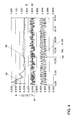
- FIG. 4 shows typical signal profiles of the lambda sensor correction explained with reference to FIG. 3.
- the individual signal curves are plotted against time t.
- a setpoint for the slope of the setpoint characteristic curve 32, ie d U LSU - model / d ⁇ setpoint, is shown at 60 .
- a curve of the regression factor R LSU is also shown at 62.
- a characteristic curve is plotted at 64, which represents noise of the voltage signal U LSU .
- the characteristic curve 64 oscillates here by a noise factor RF of 1.
- the characteristic curve of the voltage signal U LSU corresponding to the desired characteristic curve 32 (FIG. 2) is plotted at 66 for a lambda control of ⁇ 3%. This means that the value ⁇ target fluctuates (toggles) by a value of 0.97 to 1.03.
- the signal disturbances actually present by the noise signals 64 lead to a characteristic curve 68, which results from a superimposition of the characteristic curve 66 with the characteristic curve 64.
- the characteristic curve 66 thus corresponds to the desired signal, while the characteristic curve 68 corresponds to the actual signal.
- the regression factor R LSU approaches the characteristic curve 60, which corresponds to the nominal slope of the characteristic curve 32, after a short time.
- the regression factor 62 is recalculated for all newly added measured value pairs, this is the actual measured voltage U LSU of the lambda probe 16 and the value ⁇ target at any time, over all measured values of the measurement cycle.
- the measuring cycle begins, for example, each time the internal combustion engine 10 is restarted.
- the number of measured values included in the regression increases with each new pair of measured values. It becomes clear that after a short time, in particular within a few seconds, the course 62 of the regression factor approaches the course of the characteristic curve 60.
- the lambda probe correction can cause the gradient of the actual characteristic curve 34 to deviate from the target characteristic curve 32 for each linear broadband lambda probe 16. This deviation can be caused by manufacturing tolerances, aging or signs of poisoning. This is not a criterion for the correction of the lambda probe voltage signal U LSU .
- the on-board diagnosis of the motor vehicle having the internal combustion engine 10 can be carried out simultaneously by the lambda sensor correction. If the regression factor R LSU and / or the correction factor K LSU is so large that the deviation of the actual characteristic curve 34 from the target characteristic curve 32 exceeds a predeterminable maximum deviation, an error of the lambda probe 16 which can no longer be caused by the inventive method can be derived from this Correction can be compensated, be closed. The exchange of the corresponding lambda probe 16 can be displayed by providing a corresponding signal.
Applications Claiming Priority (2)
| Application Number | Priority Date | Filing Date | Title |
|---|---|---|---|
| DE10016886 | 2000-04-05 | ||
| DE10016886A DE10016886A1 (de) | 2000-04-05 | 2000-04-05 | Verfahren und Vorrichtung zur Regelung einer Verbrennungskraftmaschine |
Publications (3)
| Publication Number | Publication Date |
|---|---|
| EP1143132A2 true EP1143132A2 (fr) | 2001-10-10 |
| EP1143132A3 EP1143132A3 (fr) | 2002-08-07 |
| EP1143132B1 EP1143132B1 (fr) | 2006-06-14 |
Family
ID=7637646
Family Applications (1)
| Application Number | Title | Priority Date | Filing Date |
|---|---|---|---|
| EP01106488A Expired - Lifetime EP1143132B1 (fr) | 2000-04-05 | 2001-03-26 | Procédé et dispositif de commande d'un moteur à combustion interne |
Country Status (3)
| Country | Link |
|---|---|
| EP (1) | EP1143132B1 (fr) |
| AT (1) | ATE330117T1 (fr) |
| DE (2) | DE10016886A1 (fr) |
Cited By (4)
| Publication number | Priority date | Publication date | Assignee | Title |
|---|---|---|---|---|
| WO2002081887A2 (fr) * | 2001-04-05 | 2002-10-17 | Siemens Aktiengesellschaft | Procede pour purifier des gaz d'echappement provenant d'un moteur a combustion interne |
| WO2008122369A3 (fr) * | 2007-04-04 | 2008-11-27 | Volkswagen Ag | Régulation de lambda à adaptation de caractéristiques |
| FR2981697A1 (fr) * | 2011-10-24 | 2013-04-26 | Bosch Gmbh Robert | Procede et dispositif d'adaptation d'une regulation lambda |
| WO2013171015A1 (fr) * | 2012-05-15 | 2013-11-21 | Robert Bosch Gmbh | Procédé et unité de commande pour la compensation d'un écart de tension d'une sonde lambda à deux points |
Families Citing this family (1)
| Publication number | Priority date | Publication date | Assignee | Title |
|---|---|---|---|---|
| US10190520B1 (en) | 2017-10-12 | 2019-01-29 | Harley-Davidson Motor Company Group, LLC | Signal conditioning module for a wide-band oxygen sensor |
Citations (5)
| Publication number | Priority date | Publication date | Assignee | Title |
|---|---|---|---|---|
| US5473889A (en) | 1993-09-24 | 1995-12-12 | Honda Giken Kogyo K.K. (Honda Motor Co., Ltd. In English) | Air-fuel ratio control system for internal combustion engines |
| DE19545706A1 (de) | 1995-12-07 | 1997-06-12 | Vdo Schindling | Verfahren zur Kalibrierung einer Lambdasonde in einer Brennkraftmaschine |
| EP0686232B1 (fr) | 1993-02-26 | 1997-09-10 | ROTH-Technik GmbH & Co. Forschung für Automobil- und Umwelttechnik | Combinaison de sondes lambda |
| DE19629552C1 (de) | 1996-07-22 | 1997-12-18 | Siemens Ag | Vorrichtung zum Kompensieren der Temperaturdrift einer Abgassonde |
| EP0894187B1 (fr) | 1996-04-16 | 1999-09-01 | Siemens Aktiengesellschaft | Procede pour la commande modelisee en regime non etabli d'un moteur a combustion interne |
Family Cites Families (7)
| Publication number | Priority date | Publication date | Assignee | Title |
|---|---|---|---|---|
| JPS61195349A (ja) * | 1985-02-25 | 1986-08-29 | Ngk Spark Plug Co Ltd | 内燃機関の空燃比検出装置 |
| DE3928860A1 (de) * | 1989-08-31 | 1991-03-07 | Vdo Schindling | Verfahren und vorrichtung zur verbesserung des abgasverhaltens von gemischverdichtenden brennkraftmaschinen |
| DE4440639B4 (de) * | 1993-11-19 | 2007-08-23 | Aft Atlas Fahrzeugtechnik Gmbh | Verfahren zur Stationärsteuerung von Brennkraftmaschinen |
| DE19819461B4 (de) * | 1998-04-30 | 2004-07-01 | Siemens Ag | Verfahren zur Abgasreinigung mit Trimmregelung |
| DE19842425C2 (de) * | 1998-09-16 | 2003-10-02 | Siemens Ag | Verfahren zur Korrektur der Kennlinie einer linearen Lambda-Sonde |
| DE19852244C1 (de) * | 1998-11-12 | 1999-12-30 | Siemens Ag | Verfahren und Vorrichtung zur Abgasreinigung mit Trimmregelung |
| DE19919427C2 (de) * | 1999-04-28 | 2001-09-20 | Siemens Ag | Verfahren zur Korrektur der Kennlinie einer Breitband-Lambda-Sonde |
-
2000
- 2000-04-05 DE DE10016886A patent/DE10016886A1/de not_active Withdrawn
-
2001
- 2001-03-26 DE DE50110097T patent/DE50110097D1/de not_active Expired - Lifetime
- 2001-03-26 EP EP01106488A patent/EP1143132B1/fr not_active Expired - Lifetime
- 2001-03-26 AT AT01106488T patent/ATE330117T1/de not_active IP Right Cessation
Patent Citations (5)
| Publication number | Priority date | Publication date | Assignee | Title |
|---|---|---|---|---|
| EP0686232B1 (fr) | 1993-02-26 | 1997-09-10 | ROTH-Technik GmbH & Co. Forschung für Automobil- und Umwelttechnik | Combinaison de sondes lambda |
| US5473889A (en) | 1993-09-24 | 1995-12-12 | Honda Giken Kogyo K.K. (Honda Motor Co., Ltd. In English) | Air-fuel ratio control system for internal combustion engines |
| DE19545706A1 (de) | 1995-12-07 | 1997-06-12 | Vdo Schindling | Verfahren zur Kalibrierung einer Lambdasonde in einer Brennkraftmaschine |
| EP0894187B1 (fr) | 1996-04-16 | 1999-09-01 | Siemens Aktiengesellschaft | Procede pour la commande modelisee en regime non etabli d'un moteur a combustion interne |
| DE19629552C1 (de) | 1996-07-22 | 1997-12-18 | Siemens Ag | Vorrichtung zum Kompensieren der Temperaturdrift einer Abgassonde |
Cited By (7)
| Publication number | Priority date | Publication date | Assignee | Title |
|---|---|---|---|---|
| WO2002081887A2 (fr) * | 2001-04-05 | 2002-10-17 | Siemens Aktiengesellschaft | Procede pour purifier des gaz d'echappement provenant d'un moteur a combustion interne |
| WO2002081887A3 (fr) * | 2001-04-05 | 2002-12-12 | Siemens Ag | Procede pour purifier des gaz d'echappement provenant d'un moteur a combustion interne |
| WO2008122369A3 (fr) * | 2007-04-04 | 2008-11-27 | Volkswagen Ag | Régulation de lambda à adaptation de caractéristiques |
| FR2981697A1 (fr) * | 2011-10-24 | 2013-04-26 | Bosch Gmbh Robert | Procede et dispositif d'adaptation d'une regulation lambda |
| US9091226B2 (en) | 2011-10-24 | 2015-07-28 | Robert Bosch Gmbh | Method and device for adapting a lambda control |
| WO2013171015A1 (fr) * | 2012-05-15 | 2013-11-21 | Robert Bosch Gmbh | Procédé et unité de commande pour la compensation d'un écart de tension d'une sonde lambda à deux points |
| US9696289B2 (en) | 2012-05-15 | 2017-07-04 | Robert Bosch Gmbh | Method and control unit for compensating for a voltage offset of a two-point lambda sensor |
Also Published As
| Publication number | Publication date |
|---|---|
| EP1143132B1 (fr) | 2006-06-14 |
| ATE330117T1 (de) | 2006-07-15 |
| DE50110097D1 (de) | 2006-07-27 |
| DE10016886A1 (de) | 2001-10-18 |
| EP1143132A3 (fr) | 2002-08-07 |
Similar Documents
| Publication | Publication Date | Title |
|---|---|---|
| DE3500594C2 (de) | Zumeßsystem für eine Brennkraftmaschine zur Beeinflussung des Betriebsgemisches | |
| DE3823277C2 (fr) | ||
| EP1327138B1 (fr) | Procede et dispositif d'autodiagnostic d'un capteur de nox | |
| DE102008001569B4 (de) | Verfahren und Vorrichtung zur Adaption eines Dynamikmodells einer Abgassonde | |
| DE102010043238B4 (de) | Motorsteuersystem mit einem Algorithmus zur Aktuatorsteuerung | |
| EP0442873B1 (fr) | Procede et dispositif pour le reglage de la valeur de lambda | |
| EP0760056B1 (fr) | Procede et dispositif de commande d'un moteur a combustion interne | |
| DE69635917T2 (de) | Feststellungsvorrichtung der Katalysatorverschlechterung einer Brennkraftmaschine | |
| DE19612212B4 (de) | Diagnosevorrichtung für einen Luft/Brennstoffverhältnis-Sensor | |
| DE69918914T2 (de) | Verfahren und Vorrichtung zur Steuerung des Luft-Kraftstoffverhältnisses in einer Brennkraftmaschine | |
| DE4192104C1 (de) | Verfahren und System zum Steuern des Luft-/Kraftstoff-Verhältnisses bei einem Motor | |
| DE4122828A1 (de) | Luft-brennstoff-verhaeltnis-steuersystem | |
| DE102012221549A1 (de) | Verfahren und Vorrichtung zur Bestimmung einer Zusammensetzung eines Gasgemischs | |
| DE10211781A1 (de) | Verfahren und Einrichtung zur Überwachung und Regelung des Betriebes einer Brennkraftmaschine mit reduzierter NOx-Emission | |
| DE10256241A1 (de) | Verfahren und Vorrichtung zur Steuerung einer eine Abgasrückführung aufweisenden Brennkraftmaschine | |
| DE10309422A1 (de) | Verfahren und Vorrichtung zur Kalibrierung eines NOx-Sensors | |
| EP0187649B1 (fr) | Appareil de régulation de mélange pour moteur à combustion | |
| EP1143132B1 (fr) | Procédé et dispositif de commande d'un moteur à combustion interne | |
| DE19522659C2 (de) | Kraftstoffzufuhrsystem und Kraftstoffzufuhrverfahren für eine Verbrennungskraftmaschine | |
| EP0757168A2 (fr) | Méthode et dispositif pour la commande d'un moteur à combustion interne | |
| EP1227234B1 (fr) | Procédé et dispositif de commande d'un capteur de NOx situé dans la ligne d'échappement d'un moteur à combustion interne | |
| EP1960644A1 (fr) | Procede de diagnostic pour un catalyseur situe dans la zone des gaz d'echappement d'un moteur a combustion interne et dispositif permettant la mise en oeuvre dudit procede | |
| WO1999056012A1 (fr) | Procede d'epuration de gaz residuaires a reglage de precision | |
| EP1365234A2 (fr) | Procédé de correction du signal NOx d'un capteur de NOx | |
| DE10161901A1 (de) | Verfahren und Vorrichtung zur Kompensation des Offsets der linearen Sensorcharakteristik eines im Abgas einer Verbrennungskraftmaschine angeordneten Sensors |
Legal Events
| Date | Code | Title | Description |
|---|---|---|---|
| PUAI | Public reference made under article 153(3) epc to a published international application that has entered the european phase |
Free format text: ORIGINAL CODE: 0009012 |
|
| AK | Designated contracting states |
Kind code of ref document: A2 Designated state(s): AT BE CH CY DE DK ES FI FR GB GR IE IT LI LU MC NL PT SE TR |
|
| AX | Request for extension of the european patent |
Free format text: AL;LT;LV;MK;RO;SI |
|
| PUAL | Search report despatched |
Free format text: ORIGINAL CODE: 0009013 |
|
| AK | Designated contracting states |
Kind code of ref document: A3 Designated state(s): AT BE CH CY DE DK ES FI FR GB GR IE IT LI LU MC NL PT SE TR |
|
| AX | Request for extension of the european patent |
Free format text: AL;LT;LV;MK;RO;SI |
|
| 17P | Request for examination filed |
Effective date: 20030207 |
|
| AKX | Designation fees paid |
Designated state(s): AT BE CH CY DE DK ES FI FR GB GR IE IT LI LU MC NL PT SE TR |
|
| 17Q | First examination report despatched |
Effective date: 20050512 |
|
| GRAP | Despatch of communication of intention to grant a patent |
Free format text: ORIGINAL CODE: EPIDOSNIGR1 |
|
| GRAS | Grant fee paid |
Free format text: ORIGINAL CODE: EPIDOSNIGR3 |
|
| GRAA | (expected) grant |
Free format text: ORIGINAL CODE: 0009210 |
|
| AK | Designated contracting states |
Kind code of ref document: B1 Designated state(s): AT BE CH CY DE DK ES FI FR GB GR IE IT LI LU MC NL PT SE TR |
|
| PG25 | Lapsed in a contracting state [announced via postgrant information from national office to epo] |
Ref country code: IT Free format text: LAPSE BECAUSE OF FAILURE TO SUBMIT A TRANSLATION OF THE DESCRIPTION OR TO PAY THE FEE WITHIN THE PRESCRIBED TIME-LIMIT;WARNING: LAPSES OF ITALIAN PATENTS WITH EFFECTIVE DATE BEFORE 2007 MAY HAVE OCCURRED AT ANY TIME BEFORE 2007. THE CORRECT EFFECTIVE DATE MAY BE DIFFERENT FROM THE ONE RECORDED. Effective date: 20060614 Ref country code: GB Free format text: LAPSE BECAUSE OF FAILURE TO SUBMIT A TRANSLATION OF THE DESCRIPTION OR TO PAY THE FEE WITHIN THE PRESCRIBED TIME-LIMIT Effective date: 20060614 Ref country code: IE Free format text: LAPSE BECAUSE OF FAILURE TO SUBMIT A TRANSLATION OF THE DESCRIPTION OR TO PAY THE FEE WITHIN THE PRESCRIBED TIME-LIMIT Effective date: 20060614 Ref country code: FI Free format text: LAPSE BECAUSE OF FAILURE TO SUBMIT A TRANSLATION OF THE DESCRIPTION OR TO PAY THE FEE WITHIN THE PRESCRIBED TIME-LIMIT Effective date: 20060614 Ref country code: NL Free format text: LAPSE BECAUSE OF FAILURE TO SUBMIT A TRANSLATION OF THE DESCRIPTION OR TO PAY THE FEE WITHIN THE PRESCRIBED TIME-LIMIT Effective date: 20060614 |
|
| REG | Reference to a national code |
Ref country code: GB Ref legal event code: FG4D Free format text: NOT ENGLISH |
|
| REG | Reference to a national code |
Ref country code: CH Ref legal event code: EP |
|
| REG | Reference to a national code |
Ref country code: IE Ref legal event code: FG4D Free format text: LANGUAGE OF EP DOCUMENT: GERMAN |
|
| REF | Corresponds to: |
Ref document number: 50110097 Country of ref document: DE Date of ref document: 20060727 Kind code of ref document: P |
|
| PG25 | Lapsed in a contracting state [announced via postgrant information from national office to epo] |
Ref country code: SE Free format text: LAPSE BECAUSE OF FAILURE TO SUBMIT A TRANSLATION OF THE DESCRIPTION OR TO PAY THE FEE WITHIN THE PRESCRIBED TIME-LIMIT Effective date: 20060914 Ref country code: DK Free format text: LAPSE BECAUSE OF FAILURE TO SUBMIT A TRANSLATION OF THE DESCRIPTION OR TO PAY THE FEE WITHIN THE PRESCRIBED TIME-LIMIT Effective date: 20060914 |
|
| PG25 | Lapsed in a contracting state [announced via postgrant information from national office to epo] |
Ref country code: ES Free format text: LAPSE BECAUSE OF FAILURE TO SUBMIT A TRANSLATION OF THE DESCRIPTION OR TO PAY THE FEE WITHIN THE PRESCRIBED TIME-LIMIT Effective date: 20060925 |
|
| PG25 | Lapsed in a contracting state [announced via postgrant information from national office to epo] |
Ref country code: PT Free format text: LAPSE BECAUSE OF FAILURE TO SUBMIT A TRANSLATION OF THE DESCRIPTION OR TO PAY THE FEE WITHIN THE PRESCRIBED TIME-LIMIT Effective date: 20061114 |
|
| NLV1 | Nl: lapsed or annulled due to failure to fulfill the requirements of art. 29p and 29m of the patents act | ||
| GBV | Gb: ep patent (uk) treated as always having been void in accordance with gb section 77(7)/1977 [no translation filed] |
Effective date: 20060614 |
|
| REG | Reference to a national code |
Ref country code: IE Ref legal event code: FD4D |
|
| PLBE | No opposition filed within time limit |
Free format text: ORIGINAL CODE: 0009261 |
|
| STAA | Information on the status of an ep patent application or granted ep patent |
Free format text: STATUS: NO OPPOSITION FILED WITHIN TIME LIMIT |
|
| EN | Fr: translation not filed | ||
| 26N | No opposition filed |
Effective date: 20070315 |
|
| REG | Reference to a national code |
Ref country code: CH Ref legal event code: PL |
|
| BERE | Be: lapsed |
Owner name: VOLKSWAGEN A.G. Effective date: 20070331 |
|
| PG25 | Lapsed in a contracting state [announced via postgrant information from national office to epo] |
Ref country code: BE Free format text: LAPSE BECAUSE OF NON-PAYMENT OF DUE FEES Effective date: 20070331 |
|
| PG25 | Lapsed in a contracting state [announced via postgrant information from national office to epo] |
Ref country code: MC Free format text: LAPSE BECAUSE OF NON-PAYMENT OF DUE FEES Effective date: 20070331 |
|
| PG25 | Lapsed in a contracting state [announced via postgrant information from national office to epo] |
Ref country code: CH Free format text: LAPSE BECAUSE OF NON-PAYMENT OF DUE FEES Effective date: 20070331 Ref country code: LI Free format text: LAPSE BECAUSE OF NON-PAYMENT OF DUE FEES Effective date: 20070331 |
|
| PG25 | Lapsed in a contracting state [announced via postgrant information from national office to epo] |
Ref country code: GR Free format text: LAPSE BECAUSE OF FAILURE TO SUBMIT A TRANSLATION OF THE DESCRIPTION OR TO PAY THE FEE WITHIN THE PRESCRIBED TIME-LIMIT Effective date: 20060915 Ref country code: FR Free format text: LAPSE BECAUSE OF FAILURE TO SUBMIT A TRANSLATION OF THE DESCRIPTION OR TO PAY THE FEE WITHIN THE PRESCRIBED TIME-LIMIT Effective date: 20070309 |
|
| PG25 | Lapsed in a contracting state [announced via postgrant information from national office to epo] |
Ref country code: AT Free format text: LAPSE BECAUSE OF NON-PAYMENT OF DUE FEES Effective date: 20070326 |
|
| PG25 | Lapsed in a contracting state [announced via postgrant information from national office to epo] |
Ref country code: FR Free format text: LAPSE BECAUSE OF FAILURE TO SUBMIT A TRANSLATION OF THE DESCRIPTION OR TO PAY THE FEE WITHIN THE PRESCRIBED TIME-LIMIT Effective date: 20060614 |
|
| PG25 | Lapsed in a contracting state [announced via postgrant information from national office to epo] |
Ref country code: CY Free format text: LAPSE BECAUSE OF FAILURE TO SUBMIT A TRANSLATION OF THE DESCRIPTION OR TO PAY THE FEE WITHIN THE PRESCRIBED TIME-LIMIT Effective date: 20060614 Ref country code: LU Free format text: LAPSE BECAUSE OF NON-PAYMENT OF DUE FEES Effective date: 20070326 |
|
| PG25 | Lapsed in a contracting state [announced via postgrant information from national office to epo] |
Ref country code: TR Free format text: LAPSE BECAUSE OF FAILURE TO SUBMIT A TRANSLATION OF THE DESCRIPTION OR TO PAY THE FEE WITHIN THE PRESCRIBED TIME-LIMIT Effective date: 20060614 |
|
| PGFP | Annual fee paid to national office [announced via postgrant information from national office to epo] |
Ref country code: DE Payment date: 20200331 Year of fee payment: 20 |
|
| REG | Reference to a national code |
Ref country code: DE Ref legal event code: R071 Ref document number: 50110097 Country of ref document: DE |
|
| P01 | Opt-out of the competence of the unified patent court (upc) registered |
Effective date: 20230523 |