EP1142758A2 - Système de lampe pour véhicule - Google Patents
Système de lampe pour véhicule Download PDFInfo
- Publication number
- EP1142758A2 EP1142758A2 EP01302374A EP01302374A EP1142758A2 EP 1142758 A2 EP1142758 A2 EP 1142758A2 EP 01302374 A EP01302374 A EP 01302374A EP 01302374 A EP01302374 A EP 01302374A EP 1142758 A2 EP1142758 A2 EP 1142758A2
- Authority
- EP
- European Patent Office
- Prior art keywords
- gain
- vehicular
- lamp system
- vehicular lamp
- light distribution
- Prior art date
- Legal status (The legal status is an assumption and is not a legal conclusion. Google has not performed a legal analysis and makes no representation as to the accuracy of the status listed.)
- Withdrawn
Links
Images


Classifications
-
- B—PERFORMING OPERATIONS; TRANSPORTING
- B60—VEHICLES IN GENERAL
- B60Q—ARRANGEMENT OF SIGNALLING OR LIGHTING DEVICES, THE MOUNTING OR SUPPORTING THEREOF OR CIRCUITS THEREFOR, FOR VEHICLES IN GENERAL
- B60Q1/00—Arrangement of optical signalling or lighting devices, the mounting or supporting thereof or circuits therefor
- B60Q1/02—Arrangement of optical signalling or lighting devices, the mounting or supporting thereof or circuits therefor the devices being primarily intended to illuminate the way ahead or to illuminate other areas of way or environments
- B60Q1/04—Arrangement of optical signalling or lighting devices, the mounting or supporting thereof or circuits therefor the devices being primarily intended to illuminate the way ahead or to illuminate other areas of way or environments the devices being headlights
- B60Q1/06—Arrangement of optical signalling or lighting devices, the mounting or supporting thereof or circuits therefor the devices being primarily intended to illuminate the way ahead or to illuminate other areas of way or environments the devices being headlights adjustable, e.g. remotely-controlled from inside vehicle
- B60Q1/08—Arrangement of optical signalling or lighting devices, the mounting or supporting thereof or circuits therefor the devices being primarily intended to illuminate the way ahead or to illuminate other areas of way or environments the devices being headlights adjustable, e.g. remotely-controlled from inside vehicle automatically
- B60Q1/12—Arrangement of optical signalling or lighting devices, the mounting or supporting thereof or circuits therefor the devices being primarily intended to illuminate the way ahead or to illuminate other areas of way or environments the devices being headlights adjustable, e.g. remotely-controlled from inside vehicle automatically due to steering position
-
- B—PERFORMING OPERATIONS; TRANSPORTING
- B60—VEHICLES IN GENERAL
- B60Q—ARRANGEMENT OF SIGNALLING OR LIGHTING DEVICES, THE MOUNTING OR SUPPORTING THEREOF OR CIRCUITS THEREFOR, FOR VEHICLES IN GENERAL
- B60Q2300/00—Indexing codes for automatically adjustable headlamps or automatically dimmable headlamps
- B60Q2300/10—Indexing codes relating to particular vehicle conditions
- B60Q2300/11—Linear movements of the vehicle
- B60Q2300/112—Vehicle speed
-
- B—PERFORMING OPERATIONS; TRANSPORTING
- B60—VEHICLES IN GENERAL
- B60Q—ARRANGEMENT OF SIGNALLING OR LIGHTING DEVICES, THE MOUNTING OR SUPPORTING THEREOF OR CIRCUITS THEREFOR, FOR VEHICLES IN GENERAL
- B60Q2300/00—Indexing codes for automatically adjustable headlamps or automatically dimmable headlamps
- B60Q2300/10—Indexing codes relating to particular vehicle conditions
- B60Q2300/12—Steering parameters
- B60Q2300/122—Steering angle
-
- B—PERFORMING OPERATIONS; TRANSPORTING
- B60—VEHICLES IN GENERAL
- B60Q—ARRANGEMENT OF SIGNALLING OR LIGHTING DEVICES, THE MOUNTING OR SUPPORTING THEREOF OR CIRCUITS THEREFOR, FOR VEHICLES IN GENERAL
- B60Q2300/00—Indexing codes for automatically adjustable headlamps or automatically dimmable headlamps
- B60Q2300/30—Indexing codes relating to the vehicle environment
- B60Q2300/31—Atmospheric conditions
- B60Q2300/312—Adverse weather
-
- F—MECHANICAL ENGINEERING; LIGHTING; HEATING; WEAPONS; BLASTING
- F21—LIGHTING
- F21S—NON-PORTABLE LIGHTING DEVICES; SYSTEMS THEREOF; VEHICLE LIGHTING DEVICES SPECIALLY ADAPTED FOR VEHICLE EXTERIORS
- F21S41/00—Illuminating devices specially adapted for vehicle exteriors, e.g. headlamps
- F21S41/30—Illuminating devices specially adapted for vehicle exteriors, e.g. headlamps characterised by reflectors
- F21S41/32—Optical layout thereof
- F21S41/323—Optical layout thereof the reflector having two perpendicular cross sections having regular geometrical curves of a distinct nature
-
- F—MECHANICAL ENGINEERING; LIGHTING; HEATING; WEAPONS; BLASTING
- F21—LIGHTING
- F21S—NON-PORTABLE LIGHTING DEVICES; SYSTEMS THEREOF; VEHICLE LIGHTING DEVICES SPECIALLY ADAPTED FOR VEHICLE EXTERIORS
- F21S41/00—Illuminating devices specially adapted for vehicle exteriors, e.g. headlamps
- F21S41/60—Illuminating devices specially adapted for vehicle exteriors, e.g. headlamps characterised by a variable light distribution
- F21S41/67—Illuminating devices specially adapted for vehicle exteriors, e.g. headlamps characterised by a variable light distribution by acting on reflectors
- F21S41/675—Illuminating devices specially adapted for vehicle exteriors, e.g. headlamps characterised by a variable light distribution by acting on reflectors by moving reflectors
Definitions
- the present invention relates to a vehicular lamp system, such as a headlamp system, for a vehicle such as an automotive vehicle.
- a reflector is divided into two portions: an upper displaceable (movable) light distribution reflector; and a lower fixed light distribution reflector.
- the lower fixed light distribution reflector is designed to reflect 50 to 60 % of a total quantity of light applied to the reflector.
- the upper displaceable light distribution reflector is designed to reflect the remaining percentage of the total quantity of light.
- the lower fixed light distribution reflector serves to secure visibility of a vehicular front lighting area and an upper displaceable light distribution area is pivotally displaced toward a direction of turning so as to radiate the light from a light source onto a vehicular forwarding direction.
- a light radiation direction is continuously varied together with steering operation of a steering wheel and a gain of a radiation angle of light with respect to a steering angle is fixedly set as 1 to 1.
- a pivotal control for the upper displaceable light distribution reflector often causes visibility of surrounding of the vehicle to be insufficient during turn of vehicle on a traffic intersection.
- an extremely highly responsive pivotal control to the steering operation is carried out. This causes such an abrupt change in the light distribution as if a switch on-and-off control for light were carried out to change a light distribution so that an insufficient feeling is given to a vehicular driver.
- an object of the present invention to provide a vehicular lamp system which can improve a visibility both in a front lighting area and in turning direction of the vehicle without giving an insufficient feeling to a vehicular driver even during a run of the vehicle on a traffic intersection.
- a vehicular lamp system comprising: a displaceable light distribution section that radiates a light from a light source into a predetermined light distribution area and is enabled to displace its light distribution state toward a direction toward which a displacement angle thereof to an optical axis of the light source is formed; a drive section to drive the displaceable light distribution section to displace its light distribution state from the optical axis of the light source by the displacement angle; a steering angle sensor to detect a steering angle of a vehicular steering wheel; and a controller to control drive section to displace the light distribution section by the displacement angle in accordance with a detected value of the steering angle, the controller comprising a gain setting section that sets a gain prescribing the displacement angle with respect to detected value of the steering angle to fall in a predetermined range such as to displace the displaceable light distribution section by a predetermined displacement angle smaller than the detected value of the steering angle.
- a vehicular lamp system comprising: a displaceable light distribution section that radiates a light from a light source into a predetermined light distribution area and is enabled to displace a light distribution state thereof toward a direction toward which a displacement angle thereof to an optical axis of the light source is formed; a drive section to drive displaceable light distribution section to displace light distribution state from the optical axis of the light source by a displacement angle; a steering angle sensor to detect a steering angle of a vehicular steering wheel; and a controller to control drive section to displace the light distribution section by the displacement angle in accordance with a detected value of steering angle, the controller comprising a gain setting section that sets a gain prescribing the displacement angle of the displaceable light distributing section with respect to a detected value of the steering angle to fall in a predetermined range such as to both of a visibility of the light distribution area and an inverse of a level of insufficient feeling have exceeded predetermined preferable evaluation values in a sensory
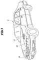
- Fig. 1 shows a perspective view of a vehicle C to which a vehicular lamp system in a first preferred embodiment is applicable.
- headlamps 20 and 20 are installed on front left and right ends of avehicle body and are controlled by signals outputted from a controller 10. Left and right headlamps 20 and 20 are symmetrically arranged and have basically the same structures.
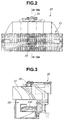
- Figs. 2 and 3 show elevation view of one headlamp 20 and cross-sectional view cut away along a line of SA - SA in Fig. 2.
- each of headlamps 20 and 20 includes: an upper displaceable light distribution section 21; a driver 22; and a lower fixed light distribution section 23.
- Upper displaceable light distribution section 21 serves to radiate light from a light source 23A, does not include a principal optical axis, and is supported pivotally in the leftward and rightward directions.
- Lower fixed light distribution section 23 includes principal optical axis.
- Driver 22 (which corresponds to a drive section) is attached onto an upper part of displaceable light distribution section 21 and is driven to pivot displaceable light distribution section 21 in horizontally leftward and rightward directions so that radiation diameter and the range can be displaced in the leftward and rightward directions as its light distribution state.
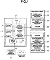
- Fig. 4 shows a circuit block diagram of the vehicular lamp system in the first preferred embodiment,representing a relationship between controller 10 and left and right headlamps 20 and 20.
- controller 10 includes arithmetic operation circuitry 11 and a pair of drive/control circuits 12 and 12.
- Arithmetic operation circuitry 11 receives an output signal from a steering angle sensor 30.
- steering angle sensor 30 detects a steering angular displacement (hereinafter, referred to as a steering angle) of a steering wheel of vehicle C and outputs a steering angle indicative signal to arithmetic operation circuitry 11 of controller 10.
- Arithmetic operation circuitry 11 sets a displacement angle ⁇ P of displaceable light distribution section 21 on basis of steering angle indicative signal and outputs a displacement angle control signal to each drive/control circuit 12 and 12.
- Each of drive/control circuits 12 and 12 outputs a drive signal to a corresponding driver 22.
- Displaceable light distribution section 21 is, thus, pivoted in leftward or rightward direction.
- driver 22 includes, for example, a DC motor as shown in Figs. 2 and 3 and a pivot section.
- arithmetic operation circuitry 11 is constituted by a microcomputer having a CPU 11a (Central Processing Unit), a RAM 11b (Random Access Memory), and an Input Port 11d, an Output Port 11e, and a common bus and drive/control circuits 12 and 12 are formed in Output Port 11e.
- CPU 11a Central Processing Unit
- RAM 11b Random Access Memory
- Input Port 11d an Input Port 11d
- Output Port 11e an Input Port 11e
- common bus and drive/control circuits 12 and 12 are formed in Output Port 11e.
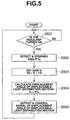
- Fig. 5 shows a processing flowchart for explaining a process flow in arithmetic operation circuitry 11.
- arithmetic operation circuitry 11 determines if each headlamp 20 (viz., each light source 23A) is turned on or not (illuminated or not).
- Arithmetic operation circuitry 11 reads (detects) steering angle indicative signal detecting steering angle ⁇ H at step S502.
- arithmetic operation circuitry 11 sets an upper limit value of a range in which a gain K prescribing rotational angle ⁇ P of displaceable light distribution section 21 with respect to steering angle ⁇ H to 1/2, sets a lower limit value thereof to 1/6, and sets gain K in that range (at a step S503) (1/6 ⁇ K ⁇ 1/2).
- Gain K is carried out in accordance with a vehicular running state of vehicle C.
- Gain K is variably set in the above predetermined range. In this case, an optimum gain K can be set in accordance with the vehicular running state.
- gain K may be set fixedly (before shipment) which falls in the range between the upper limit value of 1/2 and the lower limit value of 1/6. In this case, control becomes simple. (These steps correspond to gain setting section).
- Displacement angle ⁇ P of each displaceable light distribution section 21 is outputted from arithmetic operation circuitry 11 via corresponding drive/control circuit 12 to be displaced in the steering direction according to the steering angle through set gain K.
- Fig. 6 is a characteristic graph representing a relationship between steering angle ⁇ H and displacement angle ⁇ P of displaceable light distribution section 21. If gain K is 1/2, steering angle ⁇ H is 90 degrees and displacement angle ⁇ p is 45 degrees. If gain K is 1/3, steering angle ⁇ H is 90 degrees and displacement angle ⁇ p is 15 degrees. Reasons of setting the upper limit value of gain K to 1/2 and lower limit value of gain K to 1/6 are based on sensory evaluation test results.
- Fig. 7 shows a result of the sensory evaluation.
- the sensory evaluation test was carried out in a manner such that with gain K of displacement angle ⁇ p of displaceable light distribution section 21 with respect to steering angle ⁇ H set to plural kinds, actual vehicle experiments were made to evaluate a level of insufficient feeling given to a vehicular driver during turning o a curved road.
- Fig. 7 denotes a gain K and the vertical axis thereof denotes a sensory evaluation value.
- Fig. 7 shows that a dotted curved line indicates an inverse of level of insufficient feeling, viz., a level of sufficient feeling.
- a bold solid line in Fig. 7 shows the visibility.
- an "insufficient feeling given to vehicular driver" means a non-coincidence of a human's desire to view a place to go with an actually brightened place.
- the vehicular driver does not expect such a conventional cornering light to be turned on in response to a switch signal but actually feels a system's effect with a radiation range extended in turning direction and interlocked with the steering operation.
- gain K may be reduced to a value smaller than 2/3.
- gain K is set to 1/2 so that the angle of displacement of 30 degrees is set at 60 degree of the steering angle, it was discovered that the inverse of the level of insufficient feeling indicates an allowance (or acceptable) level.
- the upper limit value of gain K is set to 1/2, which is an allowance boundary level of the inverse of the level of insufficient feeling, as shown in Fig. 7.
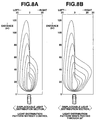
- Figs. 8A and 8B show light distribution patterns against a road surface when such a light distribution control as described above was not carried out and was carried out, respectively.
- a quantity of light on each displaceable light distribution section 21 is less than fixed light distribution section 23 including principal optical axis, a range of relatively low luminance is moved in the leftward direction and rightward directions.
- Fig. 8B shows a light distribution pattern when each displaceable light distribution section 21 is pivoted through 30 degrees in rightward direction. Since its principal axis is fixed, the light distribution toward a vehicular front direction does not change but a rightward region of low luminance is extended with 30 degree pivot angle as a center. Hence, the visibility of the vehicular surrounding area is also improved, maintaining visibility in front direction.
- Figs. 9 through 12 show a second preferred embodiment of the vehicular lamp system according to the present invention.
- Fig. 9 shows a process flowchart in arithmetic operation circuitry 11.
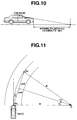
- Fig. 10 shows an explanatory view on an invisibility distance Ld.
- Fig. 11 shows an explanatory view on a visibility distance.
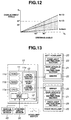
- Fig. 12 shows a graph representing gain K. It is noted that the basic structure of the vehicular lamp system in second preferred embodiment as the same as that described in first preferred embodiment.
- gain K is set in accordance with a human related information caused by vehicular driver and vehicular information caused by vehicle. That is to say, the lower limit value of gain K is set.
- the upper limit value of gain K is mechanically set in accordance with vehicle C.
- the human related information includes a visibility distance Ls from a front end of vehicle C to a point located straight at a front area of steered direction and which the vehicular driver can visually recognize and an invisibility distance Ld from front end of vehicle C to a point located at the front area and which vehicular driver cannot visually recognize.
- the vehicular driver in a passenger compartment of vehicle C is visually recognizing a vehicular forwarding line (so-called, white line), point Ps on the vehicular forwarding line which is away from the vehicular driver by visibility distance Ls is position at which vehicular driver is desired to visually be recognized.
- the vehicular information includes a vehicular characteristic value for the individual vehicle inherently has, specifically, a wheel base (for example, 2.8 meters) and a steering gear ratio (for example, 16).
- arithmetic operation circuitry 11 determines if each headlamp 20 (and 20) is turned on.
- step S902 If each headlamp 20 (and 20) is turned on, the routine goes to a step S902 in which steering angle sensor 30 detects the steering angle through steering angle sensor 30.
- control signal of angle of displacement ⁇ P of displaceable light distribution section 21 is outputted to corresponding drive/control circuit 12 and 12.
- control over each driver 22 with corresponding drive/control circuit 12 causes displaceable light distribution section 21 to be displaced toward the steered direction with set gain K.
- Fig. 10 shows invisibility distance Ld.
- Invisibility distance Ld is distance from the front end of vehicle C to a front point which driver cannot visually recognize.
- Invisibility distance Ld causes a distance for drive/control circuit to be a dead angle. Invisibility distance Ld is varied according to a vertical position of an eye point. However, invisibility distance Ld of a forward direction of a normal automotive vehicle is generally from 5 meters to 6 meters.
- lower limit value Kmin of gain Kmin is set on basis of shortest distance Ld of visibility distance Ls.
- lower limit value Kmin is set to be equal to or higher than 1/6 from sensory evaluation result of Fig. 7.
- Fig. 12 shows a relationship of angle of displacement ⁇ P of each displaceable light distribution section 21 to steering angle of ⁇ H in second embodiment.
- the upper limit value of gain K is set to 1/2 and the lower limit value thereof is set to Kmin.
- displacement angle ⁇ P of displaceable light distribution section 21 to steering angle ⁇ H is set within a gray zone shown in Fig. 12.
- Gain K is set in accordance with the human related information caused by the vehicular driver and/or in accordance with the vehicular information caused by vehicle. Hence, an accurate setting of gain K in accordance with a physical body of the vehicular driver and for each vehicle can be made.
- Light distribution state of each displaceable light distribution section 21 may accurately be moved in a direction of line of sight of vehicular driver.
- the visibility during the turning of a corner can be improved.
- Figs. 13 and 14 respectively show the vehicular lamp system in a third embodiment.
- the vehicular lamp system basically includes arithmetic operation circuitry 11 of controller 10 which receives output signals of steering angle sensor 40, which sets angle of displacement ⁇ P of each displaceable light distribution section 21 on the basis of output signals, and outputs displacement angle control signal to each drive/control circuit 12.
- Each drive/control circuit 12 outputs the drive signal to driver 22 of corresponding displaceable light distribution section 21 and each displaceable light distribution section 21 can pivotally be controlled in each of the leftward and rightward directions with respect to neutral position of vehicle C.
- Fig. 14 shows a process flowchart representing a process flow in arithmetic operation circuitry 11.
- arithmetic operation circuitry 11 determines if each headlamp 20 is turned on.
- arithmetic operation circuitry 11 detects steering angle ⁇ H from steering angle sensor 30.
- arithmetic operation circuitry 11 detects vehicular velocity V according to vehicular velocity sensor 40.
- lower limit value kmin is set to be equal to or larger than 1/6 according to sensory evaluation result of Fig. 7.
- the same advantage as the second embodiment can beachievedin the third embodiment. Since, with stability factor A and vehicular velocity V taken into further consideration, an accurate setting of the lower limit value of gain K in accordance with vehicular velocity V during turn of corner for each vehicle, light distribution section 21 can accurately be moved in direction of line of sight of the vehicular driver and visibility during turn of corner can be improved without failure.
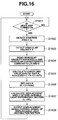
- Fig. 15 shows an operational flowchart on a fourth preferred embodiment of the vehicular lamp system according to the present invention.
- the basic structure of the vehicular lamp system in fourth embodiment is generally the same as that described in the third embodiment.
- arithmetic operation circuitry 11 determines if each headlamp 20 is turned on.
- step S1501 If Yes (turned on) at step S1501, the routine goes to a step S1502.
- arithmetic operation circuitry 11 detects steering angle ⁇ H through steering angle sensor 30.
- Arithmetic operation circuitry 11 detects vehicular velocity V through vehicular velocity sensor 40 at the next step S1503. Arithmetic operation circuitry 11 detects visibility distance Ls, characteristic constants L, N, and A of vehicle C at a step S1504.
- gain K is set to fall in a range with its lower limit value of Kmin and its upper limit value of 1/2.
- angle of displacement ⁇ P of each displaceable light distribution section 21 is outputted to corresponding drive/control circuit 12 (and 12) at the next step S1508.
- Visibility distance Ls is uniquely set to 15 meters until vehicular velocity V reaches to 40 km/h according to the sensory evaluation test result when riding actually vehicle. At this time, lower limit value Kmin of gain K is 1/6.
- the vehicular lamp system in the fourth embodiment can achieve the same advantage as that described in the case of the second embodiment.
- an average direction of a visual recognition of the vehicular driver during the vehicular turn on such a corner as described above based on the sensory evaluation provides the lower limit value of the displacement angle of each displaceable light distribution section 21, an effect of improving the visibility which matches with a driver's running condition viewing a wide range surrounding vehicular forwarding direction can be achieved without any insufficient feeling given to the vehicular driver.
- Fig. 16 shows an operational flowchart of the vehicular lamp system in a fifth preferred embodiment according to the present invention.
- the basic structure of the vehicular lamp system in the fifth embodiment is generally the same as described in the third embodiment.
- steps S1601 through S1605 are the same as those of steps S1501 through S1505 described in the fourth embodiment. To avoid a double explanation of steps, processes after a step S1606 will be explained below.
- arithmetic operation circuitry 11 calculates angle of displacement ⁇ P of each displaceable light distribution section 21 at a step S1607 and outputs control signal of angle of displacement ⁇ p to each displaceable light distribution section 21 (and 21) at a step S1608.
- gain K which provides a sufficiently high evaluation value in range of gain K in which visibility is the allowance level and level of insufficient feeling which is in allowance level was 1/3.
- a recommendable gain K is set on the basis of the sensory evaluation test result, an effect of improving the visibility which matches with a driver's running condition viewing a wide range surrounding vehicular forwarding direction can be achieved without insufficient feeling given to the vehicular driver.
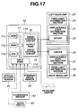
- Figs. 17 and 18 show the vehicular lamp system in a sixth preferred embodiment according to the present invention.
- Fig. 17 shows a circuit-and-functional block diagram of the vehicular lamp system in the sixth preferred embodiment according to the present invention
- Fig. 18 shows an operational flowchart executed in the sixth embodiment.
- Gain K is set according to the environmental conditions surrounding the vehicle taken into consideration.
- Environmental conditions include detection of an illuminance surrounding vehicle.
- Gain K is set in accordance with the detected illuminance.
- arithmetic operation circuitry 11 of controller 10 receives the output signals from steering angle sensor 30 and illuminance sensor 50. Arithmetic operation circuitry 11 sets angle of displacement ⁇ p of each displaceable light distribution section 21 (and 21) and outputs displacement angle control signal from each drive/control circuit 12 to driver 22 so that each of displaceable light distribution sections 21 is pivoted in the leftward and rightward directions by displacement angle ⁇ p.
- arithmetic operation circuitry 11 of controller 10 determines if each headlamp 20 is turned on at a step S1801. If Yes (turned on) at step S1801, routine goes to a step S1802 in which illuminance E is detected with an illuminance sensor 50.
- Illuminance sensor 50 is, for example, installed on an instrument panel of a vehicular compartment.
- illuminance E is equal to or lower than a predetermined value E2 (at a step S1803), the routine goes to a step S1804.
- steps S1804 through S1807 are the same as those of steps S1502 through S1505 in Fig. 15 in the fourth embodiment, these explanations of step S1808 and thereafter will only be made below.
- arithmetic operation circuitry 11 determines if illuminance E is equal to or larger than predetermined value E1. If E ⁇ E1 (Yes) at step S1808, routine goes to a step S1809.
- arithmetic operation circuitry 11 calculates angle ⁇ p of displacement in each displaceable light distribution section 21 at a step S1811.
- control signal of angle of displacement ⁇ P of each displaceable light distribution section 21 is outputted to each drive/control circuit 12.
- Illuminance value E2 may be set which provides an illumination standard of an automatic lighting mechanism. In a case where headlamps 20 are illuminated under such an environmental luminance that the automatic lighting mechanism is not illuminated, there is no effect on displacement of light distribution. A wasteful consumption of energy can be suppressed by no execution of control over each displaceable light distribution section 21.
- a range equal to or larger than illuminance value E1 or smaller than E2 indicates a dim night, indicates a time at which a road surface is relatively bright due to an illumination of a street lamp or market, or indicates a state in which insufficient feeling is not so given to vehicular driver even if gain K is high.
- illuminance value E1 may be set to a luminance value which provides a small (dim) lamp illumination standard of automatic lighting mechanism.
- the vehicular environmental condition is detected according to an operation situation of a wiper switch 50' and gain K is set in accordance with detected operation situation of wiper.
- vehicular velocity sensor 40 is utilized so that a maximum value of angle of displacement ⁇ p of each displaceable light distribution section 21 is set in accordance with vehicular velocity V.
- Fig. 20 shows a relationship between vehicular velocity V and angle of displacement ⁇ p of each displaceable light distribution section 21.
- a maximum value of displacement angle is determined as 30 degrees when vehicular velocity V is equal to or lower than 30 km/h, which is a low velocity region. In a range from 30 km/h to 50 km/h, which is a middle velocity range, as shown in Fig. 20, as vehicular velocity V is increased, displacement angle ⁇ p is set to be smaller.
- An effect of visibility due to a displacement of each displaceable light distribution section 21 is large in a low vehicular velocity region and becomes null as vehicular velocity V is increased from a middle velocity region to a high velocity region.
- vehicular velocity V falls in the middle velocity region, a frequency of driver's confirming a surrounding area of vehicle C is reduced and a line of driver's sight tends to be converged in the vehicular forwarding direction, the light distribution control to meet with an actual structure of the vehicular driver's visual recognition can be achieved.
Landscapes
- Engineering & Computer Science (AREA)
- Mechanical Engineering (AREA)
- Lighting Device Outwards From Vehicle And Optical Signal (AREA)
Applications Claiming Priority (2)
| Application Number | Priority Date | Filing Date | Title |
|---|---|---|---|
| JP2000102664A JP2001287587A (ja) | 2000-04-04 | 2000-04-04 | 車両用照明装置 |
| JP2000102664 | 2000-04-04 |
Publications (2)
| Publication Number | Publication Date |
|---|---|
| EP1142758A2 true EP1142758A2 (fr) | 2001-10-10 |
| EP1142758A3 EP1142758A3 (fr) | 2004-06-23 |
Family
ID=18616504
Family Applications (1)
| Application Number | Title | Priority Date | Filing Date |
|---|---|---|---|
| EP01302374A Withdrawn EP1142758A3 (fr) | 2000-04-04 | 2001-03-14 | Système de lampe pour véhicule |
Country Status (3)
| Country | Link |
|---|---|
| US (1) | US6578992B2 (fr) |
| EP (1) | EP1142758A3 (fr) |
| JP (1) | JP2001287587A (fr) |
Cited By (4)
| Publication number | Priority date | Publication date | Assignee | Title |
|---|---|---|---|---|
| FR2839688A1 (fr) * | 2002-05-16 | 2003-11-21 | Volkswagen Ag | Procede de reglage de l'angle de pivotement horizontal d'un projecteur de vehicule |
| EP1234717A3 (fr) * | 2001-02-21 | 2005-03-09 | Autopal S.R.O. | Dispositif pour phare de véhicule |
| FR2867119A1 (fr) * | 2004-03-05 | 2005-09-09 | Denso Corp | Dispositif destine a ajuster automatiquement l'axe de faisceau lumineux d'un phare de vehicule |
| WO2004080758A3 (fr) * | 2003-03-13 | 2006-01-26 | Hella Kgaa Hueck & Co | Systeme pour commander un dispositif d'eclairage de vehicule |
Families Citing this family (11)
| Publication number | Priority date | Publication date | Assignee | Title |
|---|---|---|---|---|
| JP3747738B2 (ja) * | 2000-05-23 | 2006-02-22 | 日産自動車株式会社 | 車両用照明装置 |
| US20030114974A1 (en) * | 2001-10-31 | 2003-06-19 | Smith James E. | Automatic directional control system for vehicle headlights |
| FR2834110B1 (fr) * | 2001-12-20 | 2004-01-30 | Valeo Vision | Dispositif d'aide a la conduite pour vehicule automobile optimise par synergie avec un eclairage adaptatif |
| US7156542B2 (en) * | 2002-12-13 | 2007-01-02 | Ford Global Technologies, Llc | Vehicle headlight system having digital beam-forming optics |
| JP4199064B2 (ja) * | 2003-07-10 | 2008-12-17 | 株式会社小糸製作所 | 車両用照明装置 |
| US20070052555A1 (en) * | 2005-09-08 | 2007-03-08 | Visteon Global Technologies, Inc. | Predictive adaptive front lighting integrated system |
| DE102008001551A1 (de) * | 2008-05-05 | 2009-11-12 | Robert Bosch Gmbh | Vorrichtung und Verfahren zum automatischen Einstellen der Leuchtdichte eines von einer Beleuchtungseinrichtung eines Fahrzeuges ausgesandten Lichtbündels in Abhängigkeit von der Sichtweite |
| US10220770B2 (en) | 2011-07-08 | 2019-03-05 | Sl Corporation | Guide lamp for vehicle |
| KR101295833B1 (ko) * | 2011-07-08 | 2013-08-12 | 에스엘 주식회사 | 차량용 방향 지시등 및 그 제어 방법 |
| US10420189B2 (en) * | 2016-05-11 | 2019-09-17 | Ford Global Technologies, Llc | Vehicle lighting assembly |
| JPWO2019039051A1 (ja) * | 2017-08-24 | 2020-08-06 | 株式会社小糸製作所 | 車両用灯具 |
Citations (2)
| Publication number | Priority date | Publication date | Assignee | Title |
|---|---|---|---|---|
| JPH0245234A (ja) | 1988-08-04 | 1990-02-15 | Koito Mfg Co Ltd | 車輌用コーナリングランプシステム |
| US5711590A (en) | 1994-12-29 | 1998-01-27 | Honda Giken Kogyo Kabushiki Kaisha | Headlight having variable light distribution |
Family Cites Families (7)
| Publication number | Priority date | Publication date | Assignee | Title |
|---|---|---|---|---|
| JPS6467440A (en) * | 1987-09-08 | 1989-03-14 | Koito Mfg Co Ltd | Cornering lamp system for vehicle |
| JPH0642407U (ja) * | 1992-11-19 | 1994-06-07 | 株式会社小糸製作所 | 車輌用コーナリングランプシステム |
| JPH09301054A (ja) * | 1996-05-20 | 1997-11-25 | Honda Motor Co Ltd | 車両用前照灯装置 |
| JPH10203232A (ja) * | 1997-01-29 | 1998-08-04 | Honda Motor Co Ltd | 車両用前照灯装置 |
| DE69931407T2 (de) * | 1998-06-16 | 2007-05-24 | Denso Corp., Kariya | System zur automatischen Einstellung der Richtung der optischen Achse eines Scheinwerfers eines Fahrzeugs |
| JP3839609B2 (ja) * | 1999-02-22 | 2006-11-01 | 株式会社小糸製作所 | 車輌用灯具装置 |
| JP3989014B2 (ja) * | 1999-12-03 | 2007-10-10 | 市光工業株式会社 | 自動車用ヘッドランプ |
-
2000
- 2000-04-04 JP JP2000102664A patent/JP2001287587A/ja active Pending
-
2001
- 2001-03-14 EP EP01302374A patent/EP1142758A3/fr not_active Withdrawn
- 2001-03-19 US US09/810,564 patent/US6578992B2/en not_active Expired - Fee Related
Patent Citations (2)
| Publication number | Priority date | Publication date | Assignee | Title |
|---|---|---|---|---|
| JPH0245234A (ja) | 1988-08-04 | 1990-02-15 | Koito Mfg Co Ltd | 車輌用コーナリングランプシステム |
| US5711590A (en) | 1994-12-29 | 1998-01-27 | Honda Giken Kogyo Kabushiki Kaisha | Headlight having variable light distribution |
Cited By (5)
| Publication number | Priority date | Publication date | Assignee | Title |
|---|---|---|---|---|
| EP1234717A3 (fr) * | 2001-02-21 | 2005-03-09 | Autopal S.R.O. | Dispositif pour phare de véhicule |
| CZ297820B6 (cs) * | 2001-02-21 | 2007-04-04 | Autopal, S. R. O. | Svetlometový systém pro motorová vozidla |
| FR2839688A1 (fr) * | 2002-05-16 | 2003-11-21 | Volkswagen Ag | Procede de reglage de l'angle de pivotement horizontal d'un projecteur de vehicule |
| WO2004080758A3 (fr) * | 2003-03-13 | 2006-01-26 | Hella Kgaa Hueck & Co | Systeme pour commander un dispositif d'eclairage de vehicule |
| FR2867119A1 (fr) * | 2004-03-05 | 2005-09-09 | Denso Corp | Dispositif destine a ajuster automatiquement l'axe de faisceau lumineux d'un phare de vehicule |
Also Published As
| Publication number | Publication date |
|---|---|
| JP2001287587A (ja) | 2001-10-16 |
| US6578992B2 (en) | 2003-06-17 |
| US20010030870A1 (en) | 2001-10-18 |
| EP1142758A3 (fr) | 2004-06-23 |
Similar Documents
| Publication | Publication Date | Title |
|---|---|---|
| US7210828B2 (en) | Vehicle lighting system | |
| EP1142758A2 (fr) | Système de lampe pour véhicule | |
| JP3865574B2 (ja) | 車両用前照灯システム | |
| EP3061653B1 (fr) | Dispositif de commande de phare de véhicule | |
| US5588733A (en) | Head lamp device for vehicle | |
| US6293686B1 (en) | Lighting device for vehicles | |
| EP2281719B1 (fr) | Système de contrôle de la distribution de la lumière dans un phare de voiture | |
| US7156542B2 (en) | Vehicle headlight system having digital beam-forming optics | |
| US6626564B2 (en) | Apparatus and method for automatically adjusting optical axis of vehicle headlights | |
| US7374320B2 (en) | Vehicular headlamp apparatus | |
| US8511872B2 (en) | Predictive adaptive front lighting for a motor vehicle | |
| US20070002571A1 (en) | Adaptive lighting system for motor vehicles | |
| US6778892B2 (en) | Vehicle headlamp optical axis control system | |
| US6547424B2 (en) | Vehicle front lamp steering controlled light distribution system | |
| JP3075966B2 (ja) | 車両用前照灯装置 | |
| US7500769B2 (en) | Head light device for vehicle | |
| US6688761B2 (en) | Vehicle headlamp automatic adjusting device with sensor failure detection means | |
| EP2394851A2 (fr) | Système d'éclairage de véhicule | |
| US6755560B2 (en) | Vehicle headlamp optical axis control system | |
| US5754100A (en) | System for assisting reverse cornering operation of vehicle and method for controlling the same | |
| JP2001277938A (ja) | 車両用前照灯光軸方向自動調整装置 | |
| US7150547B2 (en) | Turn signal and steering responsive adjustable lighting apparatus for vehicle | |
| US20040210369A1 (en) | Automatic optical axis direction adjusting device for vehicle headlight | |
| JP3675155B2 (ja) | 自動車用ヘッドライトの配光制御装置 | |
| US20070147056A1 (en) | Headlight device and method for automotive vehicle |
Legal Events
| Date | Code | Title | Description |
|---|---|---|---|
| PUAI | Public reference made under article 153(3) epc to a published international application that has entered the european phase |
Free format text: ORIGINAL CODE: 0009012 |
|
| 17P | Request for examination filed |
Effective date: 20010328 |
|
| AK | Designated contracting states |
Kind code of ref document: A2 Designated state(s): AT BE CH CY DE DK ES FI FR GB GR IE IT LI LU MC NL PT SE TR |
|
| AX | Request for extension of the european patent |
Free format text: AL;LT;LV;MK;RO;SI |
|
| PUAL | Search report despatched |
Free format text: ORIGINAL CODE: 0009013 |
|
| AK | Designated contracting states |
Kind code of ref document: A3 Designated state(s): AT BE CH CY DE DK ES FI FR GB GR IE IT LI LU MC NL PT SE TR |
|
| AX | Request for extension of the european patent |
Extension state: AL LT LV MK RO SI |
|
| AKX | Designation fees paid |
Designated state(s): DE FR GB |
|
| 17Q | First examination report despatched |
Effective date: 20050617 |
|
| STAA | Information on the status of an ep patent application or granted ep patent |
Free format text: STATUS: THE APPLICATION IS DEEMED TO BE WITHDRAWN |
|
| 18D | Application deemed to be withdrawn |
Effective date: 20051028 |