EP1140401B1 - Tool for cutting machining - Google Patents
Tool for cutting machining Download PDFInfo
- Publication number
- EP1140401B1 EP1140401B1 EP99964848A EP99964848A EP1140401B1 EP 1140401 B1 EP1140401 B1 EP 1140401B1 EP 99964848 A EP99964848 A EP 99964848A EP 99964848 A EP99964848 A EP 99964848A EP 1140401 B1 EP1140401 B1 EP 1140401B1
- Authority
- EP
- European Patent Office
- Prior art keywords
- cutting insert
- holder
- cutting
- key
- key grip
- Prior art date
- Legal status (The legal status is an assumption and is not a legal conclusion. Google has not performed a legal analysis and makes no representation as to the accuracy of the status listed.)
- Revoked
Links
Images

Classifications
-
- B—PERFORMING OPERATIONS; TRANSPORTING
- B23—MACHINE TOOLS; METAL-WORKING NOT OTHERWISE PROVIDED FOR
- B23B—TURNING; BORING
- B23B27/00—Tools for turning or boring machines; Tools of a similar kind in general; Accessories therefor
- B23B27/14—Cutting tools of which the bits or tips or cutting inserts are of special material
- B23B27/16—Cutting tools of which the bits or tips or cutting inserts are of special material with exchangeable cutting bits or cutting inserts, e.g. able to be clamped
-
- B—PERFORMING OPERATIONS; TRANSPORTING
- B23—MACHINE TOOLS; METAL-WORKING NOT OTHERWISE PROVIDED FOR
- B23B—TURNING; BORING
- B23B27/00—Tools for turning or boring machines; Tools of a similar kind in general; Accessories therefor
- B23B27/007—Tools for turning or boring machines; Tools of a similar kind in general; Accessories therefor for internal turning
-
- B—PERFORMING OPERATIONS; TRANSPORTING
- B23—MACHINE TOOLS; METAL-WORKING NOT OTHERWISE PROVIDED FOR
- B23B—TURNING; BORING
- B23B51/00—Tools for drilling machines
-
- B—PERFORMING OPERATIONS; TRANSPORTING
- B23—MACHINE TOOLS; METAL-WORKING NOT OTHERWISE PROVIDED FOR
- B23C—MILLING
- B23C5/00—Milling-cutters
- B23C5/02—Milling-cutters characterised by the shape of the cutter
- B23C5/10—Shank-type cutters, i.e. with an integral shaft
-
- B—PERFORMING OPERATIONS; TRANSPORTING
- B23—MACHINE TOOLS; METAL-WORKING NOT OTHERWISE PROVIDED FOR
- B23C—MILLING
- B23C5/00—Milling-cutters
- B23C5/16—Milling-cutters characterised by physical features other than shape
- B23C5/20—Milling-cutters characterised by physical features other than shape with removable cutter bits or teeth or cutting inserts
- B23C5/22—Securing arrangements for bits or teeth or cutting inserts
-
- B—PERFORMING OPERATIONS; TRANSPORTING
- B23—MACHINE TOOLS; METAL-WORKING NOT OTHERWISE PROVIDED FOR
- B23B—TURNING; BORING
- B23B2226/00—Materials of tools or workpieces not comprising a metal
- B23B2226/12—Boron nitride
- B23B2226/125—Boron nitride cubic [CBN]
-
- B—PERFORMING OPERATIONS; TRANSPORTING
- B23—MACHINE TOOLS; METAL-WORKING NOT OTHERWISE PROVIDED FOR
- B23B—TURNING; BORING
- B23B2226/00—Materials of tools or workpieces not comprising a metal
- B23B2226/31—Diamond
-
- B—PERFORMING OPERATIONS; TRANSPORTING
- B23—MACHINE TOOLS; METAL-WORKING NOT OTHERWISE PROVIDED FOR
- B23B—TURNING; BORING
- B23B2240/00—Details of connections of tools or workpieces
- B23B2240/04—Bayonet connections
-
- B—PERFORMING OPERATIONS; TRANSPORTING
- B23—MACHINE TOOLS; METAL-WORKING NOT OTHERWISE PROVIDED FOR
- B23B—TURNING; BORING
- B23B2260/00—Details of constructional elements
- B23B2260/138—Screw threads
-
- B—PERFORMING OPERATIONS; TRANSPORTING
- B23—MACHINE TOOLS; METAL-WORKING NOT OTHERWISE PROVIDED FOR
- B23B—TURNING; BORING
- B23B2265/00—Details of general geometric configurations
- B23B2265/34—Round
-
- B—PERFORMING OPERATIONS; TRANSPORTING
- B23—MACHINE TOOLS; METAL-WORKING NOT OTHERWISE PROVIDED FOR
- B23C—MILLING
- B23C2210/00—Details of milling cutters
- B23C2210/03—Cutting heads comprised of different material than the shank irrespective of whether the head is detachable from the shank
-
- Y—GENERAL TAGGING OF NEW TECHNOLOGICAL DEVELOPMENTS; GENERAL TAGGING OF CROSS-SECTIONAL TECHNOLOGIES SPANNING OVER SEVERAL SECTIONS OF THE IPC; TECHNICAL SUBJECTS COVERED BY FORMER USPC CROSS-REFERENCE ART COLLECTIONS [XRACs] AND DIGESTS
- Y10—TECHNICAL SUBJECTS COVERED BY FORMER USPC
- Y10T—TECHNICAL SUBJECTS COVERED BY FORMER US CLASSIFICATION
- Y10T407/00—Cutters, for shaping
- Y10T407/20—Profiled circular tool
-
- Y—GENERAL TAGGING OF NEW TECHNOLOGICAL DEVELOPMENTS; GENERAL TAGGING OF CROSS-SECTIONAL TECHNOLOGIES SPANNING OVER SEVERAL SECTIONS OF THE IPC; TECHNICAL SUBJECTS COVERED BY FORMER USPC CROSS-REFERENCE ART COLLECTIONS [XRACs] AND DIGESTS
- Y10—TECHNICAL SUBJECTS COVERED BY FORMER USPC
- Y10T—TECHNICAL SUBJECTS COVERED BY FORMER US CLASSIFICATION
- Y10T407/00—Cutters, for shaping
- Y10T407/22—Cutters, for shaping including holder having seat for inserted tool
- Y10T407/2272—Cutters, for shaping including holder having seat for inserted tool with separate means to fasten tool to holder
-
- Y—GENERAL TAGGING OF NEW TECHNOLOGICAL DEVELOPMENTS; GENERAL TAGGING OF CROSS-SECTIONAL TECHNOLOGIES SPANNING OVER SEVERAL SECTIONS OF THE IPC; TECHNICAL SUBJECTS COVERED BY FORMER USPC CROSS-REFERENCE ART COLLECTIONS [XRACs] AND DIGESTS
- Y10—TECHNICAL SUBJECTS COVERED BY FORMER USPC
- Y10T—TECHNICAL SUBJECTS COVERED BY FORMER US CLASSIFICATION
- Y10T407/00—Cutters, for shaping
- Y10T407/27—Cutters, for shaping comprising tool of specific chemical composition
Definitions
- the present invention relates to a tool for cutting machining, a cutting insert and a method for mounting such a cutting insert, according to the preambles of the independent claims.
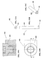
- a ball nose milling cutter comprising a milling head attached via a pull rod to a shank.
- the milling head comprises injection molded cemented carbide and has a cutting edge which extends towards the rotational axis of the tool.
- the milling head has a thread, which is integral with and thereby made in the same material as the cutting edge.
- the milling head comprises a key grip consisting of diametrical opposite planar surfaces.
- One object of the present invention is to provide a tool for cutting machining having advantages of the prior art tools.
- Another object of the present invention is to provide a tool for cutting machining and a cutting insert with improved strength and which is easy to manipulate.
- Still another object of the present invention is to provide a tool for cutting machining and a cutting insert, the designs of which make the cutting insert to be clamped harder during machining.
- Still another object of the present invention is to provide a method to easily mount such a cutting insert.
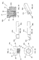
- a cutting insert 10A according to the present invention, which insert preferably is intended for longitudinal turning.
- the cutting insert 10A has a round geometry of so called R type.
- the cutting insert has an upper side 11 and a substantially planar, opposite lower side 12, interconnected by a cylindrical edge surface 13.
- the cutting insert has a circular cutting edge 14 formed along a line of intersection between the upper side 11 and the edge surface 13.
- the cutting insert 10A has a center line CL.
- the cutting insert comprises means 15 to be used for clamping the cutting insert against a holder.
- the diameter of the cutting insert is considerable larger than the diameter of the means 15.
- the means 15 is integrated with the cutting insert and thereby performed in the same material as the cutting edge 14.
- the cutting insert is made by mixing powder of sintered hard alloy with an organic binder, such as plastic, and by shaping the mixture into pellets or granules. Said pellets or granules are cast by means of an injection molding process, whereafter the obtained product is sintered at a temperature of 1300 to 1500°C.
- the injection molding technique has been more closely described in EP 96913765.2 , the contents of which hereby is incorporated in the present description.
- the means 15 projects perpendicularly from the center part of the lower side 12.
- the means 15 comprises of an externally threaded spigot 16 the center axis of which substantially coincides with the centerline CL of the cutting insert.
- the thread has one entrance and one exit.
- the thread may have at least two entrances and at least two exits of the type as is shown in Fig. 3B .
- the means 15 comprises one or more external, helically shaped grooves.
- the upper side 11 of the cutting insert 10A or the side of the insert 11 opposite said means 15 comprises at least one key grip 17.
- the key grip 17 has the shape of a profiled recess 18 intended to cooperate with a key during clamping of the cutting insert against the holder.
- the key grip 17 has a center axis, which substantially coincides with the centerline CL of the cutting insert.
- the profile of the key grip is of the type Torx® or an Allen key, or similar, that is a profile which comprises more than two surfaces for driving, preferably six such surfaces. Consequently, the centerline of the means 15 substantially coincides with the centerline of the key grip 17.
- the grip 17 is arranged within an imaginary cylinder 24, the diameter of which substantially corresponds to the average diameter of the thread 16.
- the cutting edge 14 preferably is provided in one plane. The cutting edge 14 surrounds the key grip 17 by being provided radially outside of and at a distance from the key grip relative to the centerline CL.
- Figs. 2A-2D show a turning tool 19A according to the present invention comprising a holder 20A and the cutting insert 10A.
- the holder 20A comprises a shank having one end being provided with a cutting insert pocket while the other end is provided to be fastened in a machine for turning.
- the holder is made of steel.
- the cutting insert pocket comprises a bottom surface 21 and a side support surface 22, Fig. 2D .
- the holder 20A comprises means for clamping the cutting insert in the cutting insert pocket in the shape of a threaded hole 23, which extends substantially perpendicularly to the plane of the bottom surface 21.
- the thread in the hole 23 has one entrance and one exit in the shown embodiment. Alternatively the thread may have at least two entrances and at least two exits. This can also be expressed as that the means 23 comprises one or more internal, helically shaped grooves.
- the hole 23 is provided centrally in the substantially round bottom surface.
- the side support surface 22 is part-cylindrically concave in order to fit the convex edge surface 13 of the cutting insert.
- the cutting insert 10A in the holder 20A is mounted as follows.
- the cutting insert is brought in direction towards the bottom surface 21 of the cutting insert pocket such that the centerline of the spigot 15 is aligned with the centerline of the hole 23.
- the cutting insert is pushed towards the cutting insert pocket such that the threads abut against each other.
- the cutting insert 10A and the associated threaded spigot 15 are rotated as a one-piece unit by hand or with the aid of a suitable key, not shown, in engagement with the key grip 17, until the lower side 12 of the cutting insert abuts against the bottom surface 21 of the cutting insert pocket.
- the cutting insert 10A has a diameter about 4 mm, a metric thread M2.2 and a key grip T07. More generally the interval for the diameter of the cutting insert lies in area 3-5 mm.
- the thread may be of any type and optionally right-hand or left-hand.
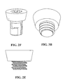
- a type of thread which fits sintered cemented carbide well is a rope thread, see Fig. 2E .
- the thread in Fig. 2E is a left-hand thread, which in connection with the round cutting edge 14 tends to tighten to the threaded connection during machining.
- the thread of the spigot 15 can be replaced by one or more helically shaped grooves, the circumferential dimension of which is smaller than 360°.
- This groove or these grooves shall then fit with corresponding protrusion/s in the hole of the holder in order to create a bayonet coupling, according to Fig. 2F , which enables indexing of the cutting insert into at least two positions with a fresh cutting edge.
- Indexing of the cutting insert may alternatively be achieved by providing a shim between the bottom surface of the holder and the lower side of the cutting insert. The thickness of the shim is chosen to half of the pitch of the thread in order to achieve indexing by 180°.
- Fig. 3A is shown an alternative embodiment of a tool 19B according to the present invention.
- the difference between this embodiment and the above-described tool is partly that the cutting insert 10B has a positive basic geometry and partly that the side support surface is missing. Thereby all cutting forces are received by the bottom surface and the thread in the holder 20B.
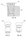
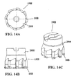
- Fig. 4A is shown an alternative embodiment of a cutting insert 10C and a tool 19C according to the present invention.
- the difference between this embodiment and the above-described tool according to Fig. 3A is that both the spigot and the hole of the holder comprise cylindrical guiding surfaces 25 and 26, respectively, provided radially beyond the imaginary cylinder 24.
- the diameters of the guiding surfaces 25, 26 are adapted for mutual slide fit. In this case all cutting forces are received by the bottom surface, the guiding surfaces 25, 26 and the thread in the holder.
- Fig. 4B is shown an alternative embodiment of a cutting insert 10C and a tool 19I according to the present invention.
- the difference between this embodiment and the above-described tool according to Fig. 4A is that the thread in the holder now has been replaced by a thread in a loose nut having a Torx ® grip.
- the nut and the cutting insert 10C are rotated relative to each other in order to mount or dismount the cutting insert.
- Fig. 4C shows the nut and the cutting insert 10C from Fig. 4A .
- Fig. 4D shows an alternative nut with external Allen grip and the cutting insert 10C from Fig. 4A .
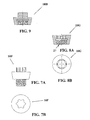
- Figs. 5A and 5B an alternative embodiment of a cutting insert 10D according to the present invention.
- the difference between this embodiment and the above-described tool according to Fig. 3A is that the edge surface or the clearance surface of the cutting insert is concave and comprises two mutually circumferential portions in order to guide breakage towards their line of intersection.
- Fig. 6 is shown an alternative embodiment of a cutting insert 10E according to the present invention in a top view.
- the key grip comprises of a hexagonal recess, a so-called Allen grip.
- Figs. 7A and 7B an alternative embodiment of a CUTTING insert 10f according to the present invention.
- the key grip includes a profiled projection on the cutting insert.
- the projection comprises a male portion for a so-called Torx ® connection.
- the projection shall cooperate with a female portion of similar but inverted geometry.
- the projection also serves as a chip former or chip breaker.
- the projection may consist of a male portion an Allen key connection, that is a projection with a hexagonal cross-section.
- the projection may however be considered as an inferior technical solution than the earlier described recess at tools of small diameters and small chip spaces.
- Figs. 8A and 8B is shown an alternative embodiment of a cutting insert 10G according to the present invention.
- the difference between this embodiment and the above-described tool according to Fig. 3A is that the helically formed grooves now are performed in a center recess 27 in the cutting insert.
- the recess 27 surpasses in the mid portion of the cutting insert into the key grip recess.
- the thread of the recess shall cooperate with a screw in the holder.
- the screw is firmly anchored in the holder or rotatable in the holder.
- the recess may include one or more internal, helically shaped grooves.
- Fig. 9 is shown an alternative embodiment of a cutting insert 10H according to the present invention.
- the difference between this embodiment and the above-described tool according to Figs. 8A and 8B is that the key grip is a projection.
- Figs. 10A and 10B an alternative embodiment of a tool 19D according to the present invention with a cutting insert 10D according to Figs. 5A and 5B .
- the difference between this embodiment and the above-described tool according to Fig. 2D is substantially that the threaded and enlarged hole of the holder is displaced a distance in direction towards the side support surface such that its center line differ in said direction from the center line of the cutting insert. Since the hole's smallest diameter is larger than the largest diameter of the spigot, the spigot can be entered longer into in the hole of the holder, whereafter rotation of the cutting insert can start.
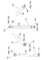
- Figs. 11A-11C is shown an alternative embodiment of a tool 19E and a cutting insert 10I according to the present invention.
- the tool 19e is intended for inside grooving and comprises a cylindrical holder and a grooving insert 10I with a projecting cutting portion.
- the cutting insert is mounted in the above-described manner and optionally the geometries of the threads may be arranged such that the final position for the cutting edge of the cutting portion is predetermined.
- Figs. 12A-12C is shown an alternative embodiment of a tool 19F and a cutting insert 10J according to the present invention.
- the tool 19F is intended for example for end milling and comprises a cylindrical cutting insert 10J, which does divide each chip.
- the cutting insert is mounted in the above-described manner and since the cutting insert comprises a number of symmetrically placed cutting portions and is to be rotated there is no need for indexing.
- the cutting insert is developed as a chip dividing cylindrical end-milling insert, a thread milling insert, a broaching insert, a truncated conical head for end-milling of dove tail slots, wherein the latter has a cone apex directed towards the holder, or similar.
- Common for all these tool is that they replace conventional end mills in high-speed steel where smaller dimensions (5 to 15 mm in diameter) often are desirable.
- Figs. 13A-13C is shown an alternative embodiment of a tool 19G and cutting insert 10B, shown in Fig. 3A, according to the present invention.
- the tool 19G is intended for example for grooving and it comprises two cutting inserts 10B, whereof one of the cutting inserts overlaps the rotational axis of the tool such that the milling cutter also can drill.
- Figs. 14A-14C is shown an alternative embodiment of a tool 19H and cutting insert 10B, showed in Fig. 3A, according to the present invention.
- the tool 19H is intended for example for face milling and it comprises eight cutting inserts 10B.
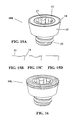
- Figs. 15A and 15B an alternative embodiment of a cutting insert 10K according to the present invention.
- the upper side 11 of the cutting insert comprises chip breaker.
- a reinforcing chamfer is connected to the cutting edge 14.
- the chamfer further connects to a concave chip surface which is in turn connects to a rising rear surface.
- Fig. 15C shows an alternative cross-section similar to Fig. 15B but without a reinforcing chamfer.
- a projection is depicted by a dotted line. A number of separate projections is then provided with even partition along of the chip surface periphery.
- Fig. 15C shows an alternative cross-section similar to Fig. 15B but without a reinforcing chamfer.
- a projection is depicted by a dotted line. A number of separate projections is then provided with even partition along of the chip surface periphery.
- FIG. 15D shows an alternative cross-section similar to Fig. 15B but without a concave chip surface.
- a planar chip surface connects to the reinforcing chamfer.
- a recess is depicted by a dotted line.
- a number of separate recesses is then provided with even partition along the chip surface periphery.
- Fig. 16 is shown an alternative embodiment of a cutting insert 10L according to the present invention.
- the upper side 11of the cutting insert comprises a ring of material which is more wear resistant than cemented carbide, such as cubic boron nitride or diamond.
- the ring surrounds the key grip.
- the present invention consequently relates to a tool for cutting machining, a cutting insert with improved strength and ease of handling and a method to easily mount such a cutting insert. More specifically by the cutting insert in itself been designed as a screw or nut the hard to handle screws used today in connection with tools according to known technique with little diameters are avoided. A solution according to the mentioned WO 98/13161 is not suitable for turning tools where there is a side support surface, since the side support surface then obstruct the movement of one arm of the key at rotation.
Landscapes
- Engineering & Computer Science (AREA)
- Mechanical Engineering (AREA)
- Milling Processes (AREA)
- Cutting Tools, Boring Holders, And Turrets (AREA)
Priority Applications (1)
| Application Number | Priority Date | Filing Date | Title |
|---|---|---|---|
| DE29924877U DE29924877U1 (de) | 1998-12-22 | 1999-12-10 | Werkzeug für die spanabhebende Bearbeitung |
Applications Claiming Priority (3)
| Application Number | Priority Date | Filing Date | Title |
|---|---|---|---|
| SE9804458 | 1998-12-22 | ||
| SE9804458A SE519123C2 (sv) | 1998-12-22 | 1998-12-22 | Skär och verktyg för skärande bearbetning samt metod för montering av skär i detta |
| PCT/SE1999/002309 WO2000037202A1 (en) | 1998-12-22 | 1999-12-10 | Tool for cutting machining |
Publications (2)
| Publication Number | Publication Date |
|---|---|
| EP1140401A1 EP1140401A1 (en) | 2001-10-10 |
| EP1140401B1 true EP1140401B1 (en) | 2013-01-23 |
Family
ID=20413783
Family Applications (1)
| Application Number | Title | Priority Date | Filing Date |
|---|---|---|---|
| EP99964848A Revoked EP1140401B1 (en) | 1998-12-22 | 1999-12-10 | Tool for cutting machining |
Country Status (7)
| Country | Link |
|---|---|
| US (1) | US6273650B1 (enExample) |
| EP (1) | EP1140401B1 (enExample) |
| JP (1) | JP4489964B2 (enExample) |
| KR (1) | KR100675922B1 (enExample) |
| CN (1) | CN1096324C (enExample) |
| SE (1) | SE519123C2 (enExample) |
| WO (1) | WO2000037202A1 (enExample) |
Families Citing this family (25)
| Publication number | Priority date | Publication date | Assignee | Title |
|---|---|---|---|---|
| DE10113633B4 (de) * | 2001-03-21 | 2006-04-13 | Jakob Lach Gmbh & Co. Kg | Profil-Drehwerkzeug |
| US20040214799A1 (en) * | 2001-05-21 | 2004-10-28 | Mutsuko Mukai | Cancerous metastasis inhibitors containing carbacyclic phosphatidic acid derivatives |
| IL145574A0 (en) * | 2001-09-24 | 2002-06-30 | Iscar Ltd | Cutting tool and cutting insert therefor |
| IL150783A0 (en) * | 2001-10-16 | 2003-02-12 | Iscar Ltd | Cutting tool and cutting insert therefor |
| IL148475A (en) * | 2002-03-04 | 2007-09-20 | Gil Hecht | Cutting Tools |
| SE526539C2 (sv) * | 2002-05-28 | 2005-10-04 | Sandvik Intellectual Property | Verktyg för spånavskiljande bearbetning där skärläget uppvisar flexibla partier. |
| SE526255C2 (sv) * | 2003-03-14 | 2005-08-09 | Sandvik Intellectual Property | Verktyg och indexerbart skär för finsvarvning av rotationssymmetriska spår i arbetsstycken |
| SE526392C2 (sv) * | 2003-08-28 | 2005-09-06 | Seco Tools Ab | Verktygsarrangemang och verktyg för spånavverkning där verktyget har en kanal av icke-cirkulärt tvärsnitt |
| US8573901B2 (en) * | 2003-09-02 | 2013-11-05 | Kennametal Inc. | Assembly for rotating a cutting insert during a turning operation and inserts used therein |
| DE102004006388A1 (de) * | 2004-02-09 | 2005-08-25 | Aleit Gmbh | Wendeplattenfräser |
| DE102004026873A1 (de) * | 2004-06-02 | 2005-12-29 | NUBIUS GROUP Präzisionswerkzeuge GmbH | Spanabhebendes Werkzeug und Schneideinlage für ein spanabhebendes Werkzeug |
| SE528299C2 (sv) * | 2004-09-24 | 2006-10-17 | Seco Tools Ab | Skärspets och skärverktyg med hållardel utformad som stympad konisk gänga |
| SE528251C2 (sv) * | 2004-09-24 | 2006-10-03 | Seco Tools Ab | Handel för verktyg samt verktyg med ett övergångsparti mellan ett gängat parti och ett stödjande parti |
| IL165294A (en) * | 2004-11-18 | 2009-07-20 | Amir Satran | Milling cutting insert and milling cutter |
| DE102006035182A1 (de) * | 2006-07-29 | 2008-01-31 | Hartmetall-Werkzeugfabrik Paul Horn Gmbh | Werkzeugsystem |
| US7648313B2 (en) * | 2006-09-19 | 2010-01-19 | Esco Technologies, Inc. | Tube end milling head |
| US7905686B2 (en) * | 2007-07-02 | 2011-03-15 | Esco Technologies, Inc. | System for removing boiler tube stubs |
| US7806633B2 (en) * | 2008-03-04 | 2010-10-05 | Kennametal Inc. | Cutting insert with threaded hole and cutting tool therefor |
| DE102010004526B4 (de) * | 2010-01-14 | 2014-05-22 | Kennametal Inc. | Zerspanungswerkzeug |
| EP2383062B1 (en) | 2010-04-30 | 2013-07-10 | Seco Tools AB | Milling tool with clamping screw having male grip at end thereof |
| CN102601397A (zh) * | 2012-03-29 | 2012-07-25 | 株洲华锐硬质合金工具有限责任公司 | 一种车火车轮圆形的车刀片及其制作方法 |
| EP2933047B1 (en) * | 2014-04-16 | 2017-03-01 | Sandvik Intellectual Property AB | A cutting tool for chip removing machining and cutting edge changing apparatus therefore |
| JP6538355B2 (ja) * | 2015-01-06 | 2019-07-03 | 中村留精密工業株式会社 | 旋削工具及び真球加工方法 |
| JP7556293B2 (ja) * | 2021-01-07 | 2024-09-26 | 三菱マテリアル株式会社 | 切削インサート、ホルダおよび刃先交換式切削工具 |
| CN117773207B (zh) * | 2024-02-27 | 2024-05-07 | 常州市卓玛工具有限公司 | 一种数控机床用硬质合金整体阶梯式锥度立铣刀盘 |
Family Cites Families (15)
| Publication number | Priority date | Publication date | Assignee | Title |
|---|---|---|---|---|
| US41517A (en) * | 1864-02-09 | Improvement in augers for boring wood | ||
| US280146A (en) * | 1883-06-26 | Cutter and holder for lathes | ||
| US1458802A (en) * | 1919-08-02 | 1923-06-12 | Williams J H & Co | Tool holder and tool |
| US1926531A (en) * | 1931-02-25 | 1933-09-12 | Charles M Hartt | Multiple tool and holder |
| SE378370B (enExample) * | 1974-10-18 | 1975-09-01 | Sandvik Ab | |
| US4197042A (en) * | 1977-12-15 | 1980-04-08 | Everede Tool Company | Countersinking tool |
| DE3106120A1 (de) * | 1981-02-19 | 1983-01-13 | Iscar Hartmetall GmbH, 7505 Ettlingen | Werkzeughalterung zur aufnahme einer schneidplatte |
| JPS59214502A (ja) * | 1983-04-04 | 1984-12-04 | ゼネラル・エレクトリツク・カンパニイ | 金属切削バイト用インサ−ト |
| IL106697A (en) | 1993-08-15 | 1996-10-16 | Iscar Ltd | A cutting board with an integral lining |
| US5733073A (en) * | 1994-03-31 | 1998-03-31 | Kennametal Inc. | Cutting tool assembly and cutting tool bit |
| SE504338C2 (sv) | 1994-06-07 | 1997-01-13 | Sandvik Ab | Skärplatta |
| SE509218C2 (sv) * | 1994-08-29 | 1998-12-21 | Sandvik Ab | Skaftverktyg |
| SE509207C2 (sv) | 1995-05-04 | 1998-12-14 | Seco Tools Ab | Verktyg för skärande bearbetning |
| US5795120A (en) * | 1996-05-13 | 1998-08-18 | Hurdle; Donald R. | Reduced-friction thread forming or thread cutting screw |
| SE509931C2 (sv) | 1996-09-27 | 1999-03-22 | Seco Tools Ab | Pinnfräs, pinnfräshuvud samt metod för montering av ett lösbart pinnfräshuvud på ett skaft till en pinnfräs |
-
1998
- 1998-12-22 SE SE9804458A patent/SE519123C2/sv not_active IP Right Cessation
-
1999
- 1999-12-10 CN CN99813702A patent/CN1096324C/zh not_active Expired - Fee Related
- 1999-12-10 JP JP2000589300A patent/JP4489964B2/ja not_active Expired - Fee Related
- 1999-12-10 KR KR1020017007921A patent/KR100675922B1/ko not_active Expired - Fee Related
- 1999-12-10 WO PCT/SE1999/002309 patent/WO2000037202A1/en not_active Ceased
- 1999-12-10 EP EP99964848A patent/EP1140401B1/en not_active Revoked
- 1999-12-22 US US09/468,904 patent/US6273650B1/en not_active Expired - Lifetime
Also Published As
| Publication number | Publication date |
|---|---|
| SE9804458D0 (sv) | 1998-12-22 |
| EP1140401A1 (en) | 2001-10-10 |
| JP4489964B2 (ja) | 2010-06-23 |
| CN1328494A (zh) | 2001-12-26 |
| SE519123C2 (sv) | 2003-01-14 |
| CN1096324C (zh) | 2002-12-18 |
| KR100675922B1 (ko) | 2007-01-29 |
| KR20020020677A (ko) | 2002-03-15 |
| US6273650B1 (en) | 2001-08-14 |
| WO2000037202A1 (en) | 2000-06-29 |
| SE9804458L (sv) | 2000-06-23 |
| JP2002532270A (ja) | 2002-10-02 |
Similar Documents
| Publication | Publication Date | Title |
|---|---|---|
| EP1140401B1 (en) | Tool for cutting machining | |
| EP1847345B1 (en) | A tool for chip removing metal machining and part therefor | |
| EP0934788B1 (en) | Endmill and cutting method | |
| EP1545818B1 (en) | Coupling in tools for chip removing machining, a tool, a cutting head and a holder | |
| EP1328366B1 (en) | Rotatable tool having a replaceable cutting part at the chip removing free end of the tool | |
| KR100582965B1 (ko) | 2개의 공구 부품 결합용 공구 커플링 및 그 방법 | |
| EP2536522B1 (en) | Tool coupling | |
| EP2136953B1 (en) | Cutting tool and method of assembling a cutting tool | |
| EP0929372B1 (en) | Milling cutter | |
| EP2101947B1 (en) | Cutting insert and cutting tool | |
| US6241433B1 (en) | Tool and cutting head for cutting machining | |
| US20030118413A1 (en) | Tool for rotary chip removal, a tool tip and a method for manufacturing a tool tip | |
| US20030039523A1 (en) | Drilling or boring tool | |
| EP1310311A2 (en) | Throw away chip clamp mechanism | |
| KR20110124156A (ko) | 밀링 공구용의 날교환가능한 밀링 인서트 | |
| WO2008014367A1 (en) | Cutting tool with replaceable tip | |
| US7320566B2 (en) | Cutting tool including detachable cutter head | |
| US7748934B2 (en) | Machine friction tool, interchangeable head and shaft | |
| EP1545819B1 (en) | Coupling in tools for chip removing machining a tool, a cutting head and a holder | |
| KR20050092401A (ko) | 나사 밀링 커터, 홀더 및 스피곳에 외부 나사를 밀링하는방법 | |
| EP3338930B1 (en) | A ball nose end mill insert, a ball nose end mill tool body and a ball nose end mill | |
| JPH063515U (ja) | 切削工具 |
Legal Events
| Date | Code | Title | Description |
|---|---|---|---|
| PUAI | Public reference made under article 153(3) epc to a published international application that has entered the european phase |
Free format text: ORIGINAL CODE: 0009012 |
|
| 17P | Request for examination filed |
Effective date: 20010505 |
|
| AK | Designated contracting states |
Kind code of ref document: A1 Designated state(s): AT BE CH CY DE DK ES FI FR GB GR IE IT LI LU MC NL PT SE |
|
| 17Q | First examination report despatched |
Effective date: 20031002 |
|
| RBV | Designated contracting states (corrected) |
Designated state(s): DE FR GB IT SE |
|
| 17Q | First examination report despatched |
Effective date: 20031002 |
|
| GRAP | Despatch of communication of intention to grant a patent |
Free format text: ORIGINAL CODE: EPIDOSNIGR1 |
|
| RIC1 | Information provided on ipc code assigned before grant |
Ipc: B23B 51/04 20060101ALI20120704BHEP Ipc: B23B 27/16 20060101AFI20120704BHEP Ipc: B23C 5/10 20060101ALI20120704BHEP Ipc: B23B 27/00 20060101ALI20120704BHEP Ipc: B23C 5/22 20060101ALI20120704BHEP |
|
| GRAS | Grant fee paid |
Free format text: ORIGINAL CODE: EPIDOSNIGR3 |
|
| GRAA | (expected) grant |
Free format text: ORIGINAL CODE: 0009210 |
|
| AK | Designated contracting states |
Kind code of ref document: B1 Designated state(s): DE FR GB IT SE |
|
| REG | Reference to a national code |
Ref country code: GB Ref legal event code: FG4D |
|
| REG | Reference to a national code |
Ref country code: DE Ref legal event code: R096 Ref document number: 69944603 Country of ref document: DE Effective date: 20130321 |
|
| PG25 | Lapsed in a contracting state [announced via postgrant information from national office to epo] |
Ref country code: SE Free format text: LAPSE BECAUSE OF FAILURE TO SUBMIT A TRANSLATION OF THE DESCRIPTION OR TO PAY THE FEE WITHIN THE PRESCRIBED TIME-LIMIT Effective date: 20130123 |
|
| PLBI | Opposition filed |
Free format text: ORIGINAL CODE: 0009260 |
|
| PLAB | Opposition data, opponent's data or that of the opponent's representative modified |
Free format text: ORIGINAL CODE: 0009299OPPO |
|
| PLAX | Notice of opposition and request to file observation + time limit sent |
Free format text: ORIGINAL CODE: EPIDOSNOBS2 |
|
| 26 | Opposition filed |
Opponent name: ISCAR LTD. Effective date: 20131023 |
|
| R26 | Opposition filed (corrected) |
Opponent name: ISCAR LTD. Effective date: 20131023 |
|
| REG | Reference to a national code |
Ref country code: DE Ref legal event code: R026 Ref document number: 69944603 Country of ref document: DE Effective date: 20131023 |
|
| PLBB | Reply of patent proprietor to notice(s) of opposition received |
Free format text: ORIGINAL CODE: EPIDOSNOBS3 |
|
| PGFP | Annual fee paid to national office [announced via postgrant information from national office to epo] |
Ref country code: GB Payment date: 20141210 Year of fee payment: 16 Ref country code: DE Payment date: 20141202 Year of fee payment: 16 |
|
| PGFP | Annual fee paid to national office [announced via postgrant information from national office to epo] |
Ref country code: FR Payment date: 20141208 Year of fee payment: 16 |
|
| PGFP | Annual fee paid to national office [announced via postgrant information from national office to epo] |
Ref country code: IT Payment date: 20141210 Year of fee payment: 16 |
|
| REG | Reference to a national code |
Ref country code: DE Ref legal event code: R103 Ref document number: 69944603 Country of ref document: DE Ref country code: DE Ref legal event code: R064 Ref document number: 69944603 Country of ref document: DE |
|
| RDAF | Communication despatched that patent is revoked |
Free format text: ORIGINAL CODE: EPIDOSNREV1 |
|
| RDAG | Patent revoked |
Free format text: ORIGINAL CODE: 0009271 |
|
| STAA | Information on the status of an ep patent application or granted ep patent |
Free format text: STATUS: PATENT REVOKED |
|
| 27W | Patent revoked |
Effective date: 20150429 |
|
| GBPR | Gb: patent revoked under art. 102 of the ep convention designating the uk as contracting state |
Effective date: 20150429 |