EP1138968A1 - Joint d'étanchéité à labyrinthe pour joint universel - Google Patents
Joint d'étanchéité à labyrinthe pour joint universel Download PDFInfo
- Publication number
- EP1138968A1 EP1138968A1 EP01107238A EP01107238A EP1138968A1 EP 1138968 A1 EP1138968 A1 EP 1138968A1 EP 01107238 A EP01107238 A EP 01107238A EP 01107238 A EP01107238 A EP 01107238A EP 1138968 A1 EP1138968 A1 EP 1138968A1
- Authority
- EP
- European Patent Office
- Prior art keywords
- sealing
- bearing bush
- universal joint
- sealing body
- seal
- Prior art date
- Legal status (The legal status is an assumption and is not a legal conclusion. Google has not performed a legal analysis and makes no representation as to the accuracy of the status listed.)
- Granted
Links
Images


Classifications
-
- F—MECHANICAL ENGINEERING; LIGHTING; HEATING; WEAPONS; BLASTING
- F16—ENGINEERING ELEMENTS AND UNITS; GENERAL MEASURES FOR PRODUCING AND MAINTAINING EFFECTIVE FUNCTIONING OF MACHINES OR INSTALLATIONS; THERMAL INSULATION IN GENERAL
- F16D—COUPLINGS FOR TRANSMITTING ROTATION; CLUTCHES; BRAKES
- F16D3/00—Yielding couplings, i.e. with means permitting movement between the connected parts during the drive
- F16D3/16—Universal joints in which flexibility is produced by means of pivots or sliding or rolling connecting parts
- F16D3/26—Hooke's joints or other joints with an equivalent intermediate member to which each coupling part is pivotally or slidably connected
- F16D3/38—Hooke's joints or other joints with an equivalent intermediate member to which each coupling part is pivotally or slidably connected with a single intermediate member with trunnions or bearings arranged on two axes perpendicular to one another
- F16D3/382—Hooke's joints or other joints with an equivalent intermediate member to which each coupling part is pivotally or slidably connected with a single intermediate member with trunnions or bearings arranged on two axes perpendicular to one another constructional details of other than the intermediate member
- F16D3/385—Bearing cup; Bearing construction; Bearing seal; Mounting of bearing on the intermediate member
-
- F—MECHANICAL ENGINEERING; LIGHTING; HEATING; WEAPONS; BLASTING
- F16—ENGINEERING ELEMENTS AND UNITS; GENERAL MEASURES FOR PRODUCING AND MAINTAINING EFFECTIVE FUNCTIONING OF MACHINES OR INSTALLATIONS; THERMAL INSULATION IN GENERAL
- F16C—SHAFTS; FLEXIBLE SHAFTS; ELEMENTS OR CRANKSHAFT MECHANISMS; ROTARY BODIES OTHER THAN GEARING ELEMENTS; BEARINGS
- F16C21/00—Combinations of sliding-contact bearings with ball or roller bearings, for exclusively rotary movement
- F16C21/005—Combinations of sliding-contact bearings with ball or roller bearings, for exclusively rotary movement the external zone of a bearing with rolling members, e.g. needles, being cup-shaped, with or without a separate thrust-bearing disc or ring, e.g. for universal joints
-
- F—MECHANICAL ENGINEERING; LIGHTING; HEATING; WEAPONS; BLASTING
- F16—ENGINEERING ELEMENTS AND UNITS; GENERAL MEASURES FOR PRODUCING AND MAINTAINING EFFECTIVE FUNCTIONING OF MACHINES OR INSTALLATIONS; THERMAL INSULATION IN GENERAL
- F16C—SHAFTS; FLEXIBLE SHAFTS; ELEMENTS OR CRANKSHAFT MECHANISMS; ROTARY BODIES OTHER THAN GEARING ELEMENTS; BEARINGS
- F16C33/00—Parts of bearings; Special methods for making bearings or parts thereof
- F16C33/72—Sealings
- F16C33/76—Sealings of ball or roller bearings
- F16C33/78—Sealings of ball or roller bearings with a diaphragm, disc, or ring, with or without resilient members
- F16C33/7803—Sealings of ball or roller bearings with a diaphragm, disc, or ring, with or without resilient members suited for particular types of rolling bearings
- F16C33/7809—Sealings of ball or roller bearings with a diaphragm, disc, or ring, with or without resilient members suited for particular types of rolling bearings for needle roller bearings
-
- F—MECHANICAL ENGINEERING; LIGHTING; HEATING; WEAPONS; BLASTING
- F16—ENGINEERING ELEMENTS AND UNITS; GENERAL MEASURES FOR PRODUCING AND MAINTAINING EFFECTIVE FUNCTIONING OF MACHINES OR INSTALLATIONS; THERMAL INSULATION IN GENERAL
- F16C—SHAFTS; FLEXIBLE SHAFTS; ELEMENTS OR CRANKSHAFT MECHANISMS; ROTARY BODIES OTHER THAN GEARING ELEMENTS; BEARINGS
- F16C33/00—Parts of bearings; Special methods for making bearings or parts thereof
- F16C33/72—Sealings
- F16C33/76—Sealings of ball or roller bearings
- F16C33/80—Labyrinth sealings
-
- F—MECHANICAL ENGINEERING; LIGHTING; HEATING; WEAPONS; BLASTING
- F16—ENGINEERING ELEMENTS AND UNITS; GENERAL MEASURES FOR PRODUCING AND MAINTAINING EFFECTIVE FUNCTIONING OF MACHINES OR INSTALLATIONS; THERMAL INSULATION IN GENERAL
- F16C—SHAFTS; FLEXIBLE SHAFTS; ELEMENTS OR CRANKSHAFT MECHANISMS; ROTARY BODIES OTHER THAN GEARING ELEMENTS; BEARINGS
- F16C2361/00—Apparatus or articles in engineering in general
- F16C2361/41—Couplings
Definitions
- the invention relates to a seal for one pivot pin accommodated in a bearing bush for a universal joint shaft with an outer and an inner, annular, insertable into the bearing bush, a sealing body permitting mutual adjustment, that are in active connection with each other.
- sealing arrangement for storing a pin in a bearing bush for Rolled universal joints known from having a a radial shaft seal provided with reinforcement, the rotatably inserted in a bore of the bearing bush and is in contact with the pin with a sealing lip.
- the sealing arrangement has another reinforced sealing ring in the area of an open End of the bearing bush rotatably on one shoulder arranged of the pin and with one to the bearing bush directed sealing lip is provided.
- the sealing arrangement has a form-fitting as another component held on an outer wall of the bearing bush Sealing cap on, with a reinforcement of the sealing ring forms a labyrinth gap.
- Sealing systems where the main seal is on a conical transition between the cylindrical Rolling element surface of the universal joint pin and the central one Articular cross body takes place are from the DE 41 31 694 A1 and known from DE 196 54 234 A1.
- a possible addition or subtraction can be used of production-related lengths and diameter tolerances the relevant components of the universal joint set the necessary pretension is difficult to maintain become.
- Sealing systems of this type therefore have one Additional seal, which is arranged in front of the main seal and this, on the one hand, from direct contact with foreign substances protects and secondly increase the sealing effect should.
- These additional seals are usually stationary at the transition between the cylindrical rolling element surface of the universal joint pin and the central universal joint body appropriate. Your sealing lips are arranged so that the seal on the bearing bush of the main seal or a combination of bearing bush and main seal takes place.
- Another problem with sealing a set of universal joints represents the contour of the universal joint, because from Manufacturing reasons is the transition between the cylindrical Rolling element tread of the universal joint pin and the central articulated cross body rounded or step-like with a cone or radius or graduated.
- This transition between the hinge pin and central articular cross body serves as the sealing surface of the main seal on which one or more Sealing lips of the sealing system, which as a rule is fixedly connected to the universal joint socket with a certain bias.
- This bias must be guaranteed for functional reasons, due to insufficient preload foreign matter in the Storage can penetrate or due to excessive preload increased friction wear occurs and thus an early bearing failure in both cases is caused.
- the invention has for its object the seal for an articulated cross pin accommodated in a bearing bush to train and arrange such that a largely permanent sealing and thus an improvement the lifespan is guaranteed.
- the object is achieved in that the two sealing bodies engaged, positively have trained sealing elements, wherein at least one sealing body is a covering part has the other sealing body and / or the bearing bush at least partially overlaps.
- both are opposite Sealing body formed like a labyrinth, interlocking Have sealing fins.
- the sealing body one or more support elements have, with at least one support element in the area of a cone transition on the hinge pin supports. This ensures that the seal is no longer directly on the hinge pin takes place, but through the interlocking, lamellar or labyrinthine Sealing elements that engage with each other or are in operative connection.
- this sealing system that from the outer sealing body and the inner seal body, both of which are annular are formed, the outer sealing body machined or machined and then in an injection mold can be inserted on the additional the contour of the inner sealing body is left out.
- the inner sealing body can be injected be so that he something during the cooling process shrinks. This creates a labyrinth gap between the two sealing bodies, which ensures that Can turn inner and outer rings against each other, without large friction losses.
- release agent Before the Injecting the inner seal body is done by applying of release agent on the two sealing bodies prevents them from sticking together. It is advantageous that the opposite surfaces have no bumps, which also causes friction losses can be reduced.
- the two support elements are spaced from each other and themselves the second support element on one to the cone transition adjoining, inclined conical surface supports. Due to the advantageous use of the two with Leave spaced support elements this easily in the transition area between the cylindrical part of the universal joint pin and the Conical transition on the surface of the universal joint pin attach and thereby also a perfect seal achieve, especially if they are preloaded be pressed against the surface of the universal joint pin.
- the main seal can be different Contours and relationships on the universal joint shaft or be adapted to the universal joint pin. Furthermore, it is easily possible to adjust the height of the support elements or the lamellar sealing elements enlarge or reduce, so that the Cross-sectional height of the main sealing area also can be increased or decreased. By diminishing the total mass of the sealing elements you gain space and can thus easily Sealing elements on a step of a step place trained hinge pin and thereby those available for rolling element storage Enlarge installation space.
- Solution is ultimately provided for that on the inner sealing body arranged sheathing part an annulus coaxial with a central axis has, for receiving one on the bearing bush arranged, annular approach is used.
- annular approach a rectangular in cross section Has recess in which the outer part of the Wrapping part can be introduced.
- both direct Have influence on the individual press dressings can control the size of the labyrinth gap and thereby the advantage can be achieved that the main Sealing effect only influenced by the diameter tolerances becomes.
- Both the outer and the inner sealing body are assembled on their respective Components pressed on and deformed in the elastic range. This can cause the labyrinth gap in the sealing system zoom out again. Due to the advantageous selection these factors can influence the friction between the inner and outer sealing body to a minimum be reduced, and you get a largely wear-free sealing.
- the covering part and the two support elements form, which consists of an elastomeric material and at least on the hinge pin and / or on a Cone part is pressed on.
- At least one Support element is designed as a sealing lip is supported on the cone part with preload, and that the interlocking sealing lamellae in about Extend direction or parallel to a transverse plane.
- a universal joint is schematic in Fig. 2 shown. Joints and cardan shafts as well as the most compensating couplings are used to compensate less Shaft displacements. You use that most Universal joint (universal joint).
- Fig. 2 are two joint forks 33 and 34 connected to each other via universal joint pins.
- the articulated forks 33, 34 can for example in Joint forged.
- the cone cross is usually there made of high quality case hardening steel and is in Rolling bearings added. It is advantageous if you long pegs for precise manufacture of the sliding surfaces and friction losses used.
- Such cardan shafts can with axle drives of motor vehicles or rail vehicles are used.
- For universal joints in automotive engineering is considered the optimal diffraction angle specified five to seven degrees, especially with Consideration of warming and efficiency. With too small Deflection angles there is a risk that bearing needles and flatten the peg due to insufficient rolling motion.
- a pivot pin consists of a cylindrical pin part 35 which by means of a Rolling body 3 rotatably arranged in a bearing bush 2 is.
- the bearing bush 2 consists of a cylindrical housing part 36 with a bottom 8, which has a flat end face 17 has. At the front end of the bearing bush 2 there is an annular recess for receiving of at least one first ring-shaped outer sealing body 4, which with a second inner, also ring-shaped sealing body 5 via form-fitting sealing elements or sealing lamellae 9 operatively connected is.
- the two sealing bodies 4 and 5 essentially form the main sealing system between the outside and the inner area of the bearing bush 2.
- first sealing body 4 which in the annular recess 37 can be pressed in to a good frictional connection between the inner surface of the sealing body 4 and the inner surface of the recess.
- annular sealing body 4 also belongs to the second inner ring Sealing body 5.
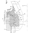
- Both sealing bodies 4 and 5 have numerous, arranged side by side, labyrinthine trained sealing elements or sealing lamellae 9 3, which is trapezoidal in cross section according to FIG could be.
- the sealing lamellae 9 are designed and arranged in such a way that that between the opposite sealing surfaces a slight gap remains, so that between the two sealing bodies 4 and 5 a rotary movement is possible.
- the outer seal body has three side by side Sealing lamellae 9, to which a cylindrical Approach 39 connects that into a corresponding one recess 40 provided in the inner sealing body 5 is precisely fitted. In this way, the inside End face of the recess 40 against the end face of the sealing body 4 press and thus the Sealing body 4 in turn against the shoulder 16 of the bearing bush 2 press.
- the second seal body 5 is referenced to FIG its sealing lamella 9 is a mirror image of the first Seal body 4 formed, the two opposite Sealing fins 9 according to FIG. 1 in one constant intervention.
- the 1 has at least two support elements 22 arranged at a distance from one another and 23, wherein the one support element 22 in one Area 14 of the cone transition is provided.
- the area 14 lies between the right end according to FIG. 3 of the cylindrical pivot part 35 and one itself adjoining, widening cone part 30.
- the transition region 14 has a curved course.
- a part of the support element 22, 23 sits on the cylindrical part and part of the support element the expanding part of the hinge pin 1.
- the support element 22 adjoins one Surface 41 of the cone part 30 a chamber or recess 15 and the second support element 23 thereon.
- the two sealing bodies 4, 5 can be made of an elastomer Material made of thermoplastics such as polyolefins or be formed from a polyvenyl compound.
- the outer sealing body 4 is connected to the bearing bush 2 and the inner sealing body 5 with the universal joint pin 1 each applied by means of an interference fit to this way foreign objects penetrate into the interior to avoid the bearing bush and also one Loss of lubricant through the stomata in the area the joints to be excluded.
- the two sealing bodies 4 become sealing devices and 5 assembled before installation.
- the outer seal body 4 can be machined or machined and then placed in an appropriate injection mold on the additional outer contour of the inner Sealing body 5 is recessed. Now he can inner sealing body are injected, he shrinks somewhat during the cooling process. This creates between the surfaces of the sealing fins 9 a labyrinth gap so that it is ensured that the two interacting sealing bodies 4 and 5 can be rotated against each other.
- the advantageous embodiment of the two sealing bodies 4, 5 creates the possibility of this with appropriate Adaptation of any surface to a hinge pin 1 to apply.
- To the cross-sectional height To reduce the seal body, do this accordingly the sealing blades 9 in their cross-sectional height reduced. This results in a gain in installation space.
- the support element 23 is advantageously located Biasing force against the surface 41 of the cone part 30 on. This gives a perfect seal between the outside and the inside of the universal joint pin.
- the sealing lamellas extend 9 preferably in the radial direction, d. H. they extend approximately parallel to one Transverse plane 31, which has a central axis 11 in a right Angle cuts. Between the facing each other Surfaces of the sealing lamella 9 is located Air gap or labyrinth gap 10.
- the outer diameter of the outer, ring-shaped Sealing body 4 is over the entire length of the Sealing body constant.
- an approach 6 which is in a second sealing body 5 provided annular space 24 extends.
- annular space 24 extends at the front end of the bearing bush 2 .
- a gradation or recess 25 with an end face 26 and a second end face 26 'is provided.
- Wrapping part 7, which is fixed to the outer, annular Sealing body 4 is connected.
- the outside diameter of the covering part 7 corresponds to the area of the end face 26 the graduation of the outer diameter of the bearing bush 2.
- the approach 6 of the bearing bush 2 thus forms the recess 25 in connection with the annular space 24 of the outer sealing body 4 also a labyrinth seal.
- the approximately parallel with respect to the transverse plane 31 form extending end faces 26, 26 'of the approach 6 with the recess 25 and also on one Transverse plane end faces 27 and 27 'of the wrapping part 7 with the annular space 24 each an annular gap 28 or 29.
- the outer wall of the sealing body 4 has approximately same outer diameter of the lower wall portion 43 of the Recess 37.
- the approach 6 is against the outer circumference of the sealing body 4 and the bottom of the annular space 24 and thus also forms a labyrinth-like sealing gap 12.
- the approach 39 lies with its interior Face against the face end of the outer seal body 4 and presses in the position shown in FIG. 3 the sealing body 4 against the shoulder 16. So that also the axial movement of the universal joint pin 1 in the direction the bottom 8 of the bearing bush 2 limited.
- the axial Fixation of the universal joint pin 1 is also carried out by the installation of the inner end face of the hinge pin 1 against the end face 17 of the base 8.
Applications Claiming Priority (2)
| Application Number | Priority Date | Filing Date | Title |
|---|---|---|---|
| DE10015571A DE10015571A1 (de) | 2000-03-29 | 2000-03-29 | Labyrinthdichtung für eine Gelenkkreuzwelle |
| DE10015571 | 2000-03-29 |
Publications (2)
| Publication Number | Publication Date |
|---|---|
| EP1138968A1 true EP1138968A1 (fr) | 2001-10-04 |
| EP1138968B1 EP1138968B1 (fr) | 2005-08-31 |
Family
ID=7636809
Family Applications (1)
| Application Number | Title | Priority Date | Filing Date |
|---|---|---|---|
| EP01107238A Expired - Lifetime EP1138968B1 (fr) | 2000-03-29 | 2001-03-23 | Joint d'étanchéité à labyrinthe pour joint universel |
Country Status (4)
| Country | Link |
|---|---|
| US (1) | US6547668B2 (fr) |
| EP (1) | EP1138968B1 (fr) |
| DE (2) | DE10015571A1 (fr) |
| ES (1) | ES2246952T3 (fr) |
Cited By (2)
| Publication number | Priority date | Publication date | Assignee | Title |
|---|---|---|---|---|
| EP1413788A1 (fr) * | 2002-10-24 | 2004-04-28 | TRW Automotive U.S. LLC | Joint universel |
| EP2798246A4 (fr) * | 2011-10-12 | 2015-09-23 | Baldor Electric Co | Joint d'isolation monté sur un palier |
Families Citing this family (7)
| Publication number | Priority date | Publication date | Assignee | Title |
|---|---|---|---|---|
| US20040171427A1 (en) * | 2003-02-28 | 2004-09-02 | Wagner John Brian | U-joint face seal |
| US7512070B2 (en) * | 2003-06-23 | 2009-03-31 | Intel Corporation | Adaptive use of a transmit opportunity |
| US8630168B2 (en) * | 2003-06-23 | 2014-01-14 | Intel Corporation | Adaptive use of a transmit opportunity |
| US7695390B2 (en) * | 2006-09-18 | 2010-04-13 | Gm Global Technology Operations, Inc. | Multi-speed transmission |
| DE102009048290A1 (de) * | 2009-10-05 | 2011-04-07 | Schaeffler Technologies Gmbh & Co. Kg | Wälzlager, insbesondere Radial-Nadellager |
| CA2734901C (fr) * | 2011-03-23 | 2018-05-22 | Hitek Urethane Global Ltd. | Joint elastomere pour tetes rotatives |
| JP5912480B2 (ja) * | 2011-12-12 | 2016-04-27 | 株式会社Roki | シール部材 |
Citations (8)
| Publication number | Priority date | Publication date | Assignee | Title |
|---|---|---|---|---|
| US4377312A (en) * | 1981-03-06 | 1983-03-22 | Dana Corporation | Bearing seal |
| US4440401A (en) * | 1982-05-15 | 1984-04-03 | Skf Kugellagerfabriken Gmbh | Seal assembly for bearing cups slidable in axial direction in bore |
| DE8416023U1 (de) * | 1984-08-23 | FAG Kugelfischer Georg Schäfer KGaA, 8720 Schweinfurt | Dichtung aus elastischem Werkstoff für Gelenkbüchsen | |
| US4903971A (en) * | 1987-11-10 | 1990-02-27 | Skf Gmbh | Seal for bearing bushings |
| DE4128179A1 (de) * | 1991-08-24 | 1993-02-25 | Skf Gmbh | Abdichtung fuer lagerbuechsen, insbesondere fuer kreuzgelenke |
| US5407387A (en) * | 1993-02-12 | 1995-04-18 | The Zeller Corporation | Universal joint seal |
| US5626520A (en) * | 1995-06-14 | 1997-05-06 | The Zeller Corporation | Reversible universal joint seal |
| DE19637553C1 (de) * | 1996-06-05 | 1997-11-27 | Gkn Automotive Ag | Zapfenkreuzgarnitur mit einer Abdichtungsanordnung |
Family Cites Families (10)
| Publication number | Priority date | Publication date | Assignee | Title |
|---|---|---|---|---|
| US3446507A (en) * | 1966-09-21 | 1969-05-27 | Gen Motors Corp | Universal joint bearing seal assembly |
| BE792674A (nl) * | 1971-12-14 | 1973-06-13 | Wavin Bv | Buisverbinding met klemring |
| US4337628A (en) * | 1980-08-20 | 1982-07-06 | Borg-Warner Corporation | Universal joint with unitary face seal and retainer assembly |
| FR2566071B1 (fr) * | 1984-06-15 | 1989-03-10 | Glaenzer Spicer Sa | Dispositif d'etancheite pour joint de cardan |
| DE3639315C1 (de) * | 1986-11-17 | 1988-04-14 | Gelenkwellenbau Gmbh | Vorrichtung zum Abdichten eines Waelzlagers,insbesondere von Lagerbuechsen eines Kreuzgelenkes |
| DE4131694C2 (de) | 1991-09-24 | 2000-02-17 | Schaeffler Waelzlager Ohg | Dichtungsanordnung für eine Lagerbüchse |
| DE4408831A1 (de) | 1994-03-16 | 1995-09-21 | Schaeffler Waelzlager Kg | Abdichtung für Gelenkkreuzbüchsen |
| US5588915A (en) | 1995-12-26 | 1996-12-31 | Dana Corporation | Seal and seal guard assembly for universal joint |
| JP3247048B2 (ja) * | 1996-08-28 | 2002-01-15 | 矢崎総業株式会社 | リップ付きゴム製品 |
| US6095925A (en) * | 1997-10-10 | 2000-08-01 | Dana Corporation | Seal assembly and seal guard for a universal joint |
-
2000
- 2000-03-29 DE DE10015571A patent/DE10015571A1/de not_active Withdrawn
-
2001
- 2001-03-23 ES ES01107238T patent/ES2246952T3/es not_active Expired - Lifetime
- 2001-03-23 DE DE50107246T patent/DE50107246D1/de not_active Expired - Lifetime
- 2001-03-23 EP EP01107238A patent/EP1138968B1/fr not_active Expired - Lifetime
- 2001-03-27 US US09/818,069 patent/US6547668B2/en not_active Expired - Fee Related
Patent Citations (8)
| Publication number | Priority date | Publication date | Assignee | Title |
|---|---|---|---|---|
| DE8416023U1 (de) * | 1984-08-23 | FAG Kugelfischer Georg Schäfer KGaA, 8720 Schweinfurt | Dichtung aus elastischem Werkstoff für Gelenkbüchsen | |
| US4377312A (en) * | 1981-03-06 | 1983-03-22 | Dana Corporation | Bearing seal |
| US4440401A (en) * | 1982-05-15 | 1984-04-03 | Skf Kugellagerfabriken Gmbh | Seal assembly for bearing cups slidable in axial direction in bore |
| US4903971A (en) * | 1987-11-10 | 1990-02-27 | Skf Gmbh | Seal for bearing bushings |
| DE4128179A1 (de) * | 1991-08-24 | 1993-02-25 | Skf Gmbh | Abdichtung fuer lagerbuechsen, insbesondere fuer kreuzgelenke |
| US5407387A (en) * | 1993-02-12 | 1995-04-18 | The Zeller Corporation | Universal joint seal |
| US5626520A (en) * | 1995-06-14 | 1997-05-06 | The Zeller Corporation | Reversible universal joint seal |
| DE19637553C1 (de) * | 1996-06-05 | 1997-11-27 | Gkn Automotive Ag | Zapfenkreuzgarnitur mit einer Abdichtungsanordnung |
Cited By (3)
| Publication number | Priority date | Publication date | Assignee | Title |
|---|---|---|---|---|
| EP1413788A1 (fr) * | 2002-10-24 | 2004-04-28 | TRW Automotive U.S. LLC | Joint universel |
| US6964613B2 (en) | 2002-10-24 | 2005-11-15 | Trw Inc. | Universal joint |
| EP2798246A4 (fr) * | 2011-10-12 | 2015-09-23 | Baldor Electric Co | Joint d'isolation monté sur un palier |
Also Published As
| Publication number | Publication date |
|---|---|
| ES2246952T3 (es) | 2006-03-01 |
| US20010034270A1 (en) | 2001-10-25 |
| US6547668B2 (en) | 2003-04-15 |
| DE50107246D1 (de) | 2005-10-06 |
| DE10015571A1 (de) | 2001-10-11 |
| EP1138968B1 (fr) | 2005-08-31 |
Similar Documents
| Publication | Publication Date | Title |
|---|---|---|
| EP0274584B1 (fr) | Dispositif d'étanchéité pour la coupelle de palier d'un joint universel | |
| EP2561241B1 (fr) | Ensemble d'étanchéité pour palier à roulement | |
| DD237535A5 (de) | Elastisches gelenk, kupplung oder dergleichen | |
| EP0050213B1 (fr) | Logement des paliers à alignement automatique | |
| DE19912432A1 (de) | Ausrücklager | |
| EP2603708A1 (fr) | Ensemble d'étanchéité pour palier de roulement | |
| EP1481175A1 (fr) | Articulation de voie opposee | |
| EP0330993B1 (fr) | Dispositif de palier pour un croisillon d'un joint de cardan | |
| EP1132642B1 (fr) | Support en gomme | |
| EP2886896A2 (fr) | Palier à roulement doté d'une unité d'étanchéité pour palier à roulement | |
| DE10209933A1 (de) | Gegenbahngelenk | |
| DE60308459T2 (de) | Kreuzkupplung | |
| DE19502246A1 (de) | Dichtungseinrichtung für ein Kreuzgelenk | |
| EP1138968A1 (fr) | Joint d'étanchéité à labyrinthe pour joint universel | |
| EP1676038B1 (fr) | Palier è rotulé servant notamment au centrage mutuel de deux extrimités d'abres | |
| DE2708137C2 (de) | Abdichtung für die Lagerkörper des Kreuzes eines Kreuzgelenkes | |
| EP0564875B1 (fr) | Dispositif d'étanchéité pour joint universal | |
| EP1225355B1 (fr) | Système d'étanchéite pour un palier de joint de cardan | |
| DE3805443A1 (de) | Dichtung, insbesondere radialwellendichtung oder manschettendichtung | |
| DE10157935A1 (de) | Befestigungsring für eine Dichtmanschette eines Kugelgelenks | |
| DE10344804B4 (de) | Schwenklagerung | |
| DE102017210135B4 (de) | Kugelkäfig für VL- und CG-Gelenke | |
| EP1016800B1 (fr) | Cartouche d'étanchéité pour un palier d'arbre | |
| DE2710768A1 (de) | Kugel-pfannen-gelenk | |
| DE2756809C2 (fr) |
Legal Events
| Date | Code | Title | Description |
|---|---|---|---|
| PUAI | Public reference made under article 153(3) epc to a published international application that has entered the european phase |
Free format text: ORIGINAL CODE: 0009012 |
|
| AK | Designated contracting states |
Kind code of ref document: A1 Designated state(s): DE ES FR GB IT Kind code of ref document: A1 Designated state(s): AT BE CH CY DE DK ES FI FR GB GR IE IT LI LU MC NL PT SE TR |
|
| AX | Request for extension of the european patent |
Free format text: AL;LT;LV;MK;RO;SI |
|
| 17P | Request for examination filed |
Effective date: 20020221 |
|
| AKX | Designation fees paid |
Free format text: DE ES FR GB IT |
|
| 17Q | First examination report despatched |
Effective date: 20041103 |
|
| GRAP | Despatch of communication of intention to grant a patent |
Free format text: ORIGINAL CODE: EPIDOSNIGR1 |
|
| GRAS | Grant fee paid |
Free format text: ORIGINAL CODE: EPIDOSNIGR3 |
|
| GRAA | (expected) grant |
Free format text: ORIGINAL CODE: 0009210 |
|
| AK | Designated contracting states |
Kind code of ref document: B1 Designated state(s): DE ES FR GB IT |
|
| REG | Reference to a national code |
Ref country code: GB Ref legal event code: FG4D Free format text: NOT ENGLISH |
|
| REF | Corresponds to: |
Ref document number: 50107246 Country of ref document: DE Date of ref document: 20051006 Kind code of ref document: P |
|
| GBT | Gb: translation of ep patent filed (gb section 77(6)(a)/1977) |
Effective date: 20051005 |
|
| REG | Reference to a national code |
Ref country code: ES Ref legal event code: FG2A Ref document number: 2246952 Country of ref document: ES Kind code of ref document: T3 |
|
| ET | Fr: translation filed | ||
| PLBE | No opposition filed within time limit |
Free format text: ORIGINAL CODE: 0009261 |
|
| STAA | Information on the status of an ep patent application or granted ep patent |
Free format text: STATUS: NO OPPOSITION FILED WITHIN TIME LIMIT |
|
| 26N | No opposition filed |
Effective date: 20060601 |
|
| PGFP | Annual fee paid to national office [announced via postgrant information from national office to epo] |
Ref country code: ES Payment date: 20100326 Year of fee payment: 10 |
|
| PGFP | Annual fee paid to national office [announced via postgrant information from national office to epo] |
Ref country code: FR Payment date: 20100402 Year of fee payment: 10 Ref country code: IT Payment date: 20100327 Year of fee payment: 10 |
|
| PGFP | Annual fee paid to national office [announced via postgrant information from national office to epo] |
Ref country code: GB Payment date: 20100322 Year of fee payment: 10 |
|
| PGFP | Annual fee paid to national office [announced via postgrant information from national office to epo] |
Ref country code: DE Payment date: 20100324 Year of fee payment: 10 |
|
| GBPC | Gb: european patent ceased through non-payment of renewal fee |
Effective date: 20110323 |
|
| REG | Reference to a national code |
Ref country code: FR Ref legal event code: ST Effective date: 20111130 |
|
| PG25 | Lapsed in a contracting state [announced via postgrant information from national office to epo] |
Ref country code: DE Free format text: LAPSE BECAUSE OF NON-PAYMENT OF DUE FEES Effective date: 20111001 Ref country code: FR Free format text: LAPSE BECAUSE OF NON-PAYMENT OF DUE FEES Effective date: 20110331 |
|
| REG | Reference to a national code |
Ref country code: DE Ref legal event code: R119 Ref document number: 50107246 Country of ref document: DE Effective date: 20111001 |
|
| PG25 | Lapsed in a contracting state [announced via postgrant information from national office to epo] |
Ref country code: IT Free format text: LAPSE BECAUSE OF NON-PAYMENT OF DUE FEES Effective date: 20110323 Ref country code: GB Free format text: LAPSE BECAUSE OF NON-PAYMENT OF DUE FEES Effective date: 20110323 |
|
| REG | Reference to a national code |
Ref country code: ES Ref legal event code: FD2A Effective date: 20120424 |
|
| PG25 | Lapsed in a contracting state [announced via postgrant information from national office to epo] |
Ref country code: ES Free format text: LAPSE BECAUSE OF NON-PAYMENT OF DUE FEES Effective date: 20110324 |