EP1138881A2 - Turbinengehäuse für eine axial durchströmte Gasturbine - Google Patents
Turbinengehäuse für eine axial durchströmte Gasturbine Download PDFInfo
- Publication number
- EP1138881A2 EP1138881A2 EP01106613A EP01106613A EP1138881A2 EP 1138881 A2 EP1138881 A2 EP 1138881A2 EP 01106613 A EP01106613 A EP 01106613A EP 01106613 A EP01106613 A EP 01106613A EP 1138881 A2 EP1138881 A2 EP 1138881A2
- Authority
- EP
- European Patent Office
- Prior art keywords
- outer shell
- turbine
- inner component
- turbine housing
- hot gas
- Prior art date
- Legal status (The legal status is an assumption and is not a legal conclusion. Google has not performed a legal analysis and makes no representation as to the accuracy of the status listed.)
- Granted
Links
Images

Classifications
-
- F—MECHANICAL ENGINEERING; LIGHTING; HEATING; WEAPONS; BLASTING
- F01—MACHINES OR ENGINES IN GENERAL; ENGINE PLANTS IN GENERAL; STEAM ENGINES
- F01D—NON-POSITIVE DISPLACEMENT MACHINES OR ENGINES, e.g. STEAM TURBINES
- F01D25/00—Component parts, details, or accessories, not provided for in, or of interest apart from, other groups
- F01D25/24—Casings; Casing parts, e.g. diaphragms, casing fastenings
- F01D25/26—Double casings; Measures against temperature strain in casings
-
- F—MECHANICAL ENGINEERING; LIGHTING; HEATING; WEAPONS; BLASTING
- F01—MACHINES OR ENGINES IN GENERAL; ENGINE PLANTS IN GENERAL; STEAM ENGINES
- F01D—NON-POSITIVE DISPLACEMENT MACHINES OR ENGINES, e.g. STEAM TURBINES
- F01D25/00—Component parts, details, or accessories, not provided for in, or of interest apart from, other groups
- F01D25/24—Casings; Casing parts, e.g. diaphragms, casing fastenings
- F01D25/243—Flange connections; Bolting arrangements
-
- F—MECHANICAL ENGINEERING; LIGHTING; HEATING; WEAPONS; BLASTING
- F05—INDEXING SCHEMES RELATING TO ENGINES OR PUMPS IN VARIOUS SUBCLASSES OF CLASSES F01-F04
- F05D—INDEXING SCHEME FOR ASPECTS RELATING TO NON-POSITIVE-DISPLACEMENT MACHINES OR ENGINES, GAS-TURBINES OR JET-PROPULSION PLANTS
- F05D2220/00—Application
- F05D2220/30—Application in turbines
- F05D2220/32—Application in turbines in gas turbines
Definitions
- the present invention relates to a turbine housing for an axially flowing gas turbine, at least a hot gas space between a compressor stage and encloses a turbine stage and an outer shell as an outer boundary and an inner component has the hot gas space over an intermediate space separates from the outer shell.
- Turbine housings manufactured are system-dependent limited in their mechanical and thermal resilience.
- the object of the present invention is therein, a turbine housing for an axially flow To provide gas turbine that can be manufactured inexpensively is and very high pressures and temperatures withstands. So the turbine housing should be in the range of one Compressor end pressure of over 30 bar at temperatures can be operated from 550 to 570 ° C without any problems.
- the task is with the turbine housing according to claim 1 solved.
- Advantageous embodiments of this Housing are the subject of the dependent claims.
- the invention Turbine housing that has at least one hot gas space between a compressor stage and a turbine stage encloses and an outer shell as an outer boundary has a separate from the outer shell provided internal component that the hot gas space over a Separate the space from the outer shell.
- the inner component is like this over two axial interfaces connected to the outer shell that the space is sealed against the hot gas space.
- the turbine housing according to the invention is thus out an outer shell and an inner component.
- the inner component hereinafter also called the hot gas component referred to, designed so that it both the circumferential stresses due to the pressure difference between the hot gas space and the space as well as the high one withstands the temperature in the hot gas chamber.
- This hot gas component is therefore preferably made of one high quality material.
- the outer shell only needs to be sufficient have a rigid construction around the static ones Forces of the gas turbine transmitted and on the other hand the pressure difference between the gap and the To be able to withstand the surrounding atmosphere.
- the temperature, that acts on the outer shell is due to the Separation from the hot gas space via the inner component and the space significantly reduced. This temperature load can be done by a suitable cooling air duct in the between the inner component and the outer shell formed space can also be counteracted. This also reduces that in steam and gas turbines known phenomenon of the so-called usually caused by a deformation of the stator becomes.
- the Turbine housing is the inner component by surface pressure acting in the axial direction connected to the outer shell.
- the outer shell preferably two inward circumferential Projections or webs as axial interfaces, on which the inner component is placed.
- the inner component this requires sufficient flexibility in the axial direction have to over the entire operating cycle of the gas turbine at the axial interfaces to the outer housing sufficient surface pressure for the sealing effect to be achieved build up.
- the sealing effect is preferred achieved by metallic sealing, both the axial interfaces as well as those in contact coming surfaces of the inner component metallic sealing surfaces exhibit.
- the outer shell with the webs a sufficiently rigid construction have the due to the surface pressure for to absorb metallic sealing occurring axial forces. This configuration allows the invention Turbine housing realized in a very simple way become.
- the materials for the outer shell and that Inner component selected such that during operation sufficient surface pressure between the interfaces the components for sealing are available.
- the thermal coefficient of linear expansion of the material lower is preferably chosen for the inner component than that for the outer shell. Different thermal Strains due to the effects on both components different temperatures can be compensated become.
- the materials are in any case chosen so that the sealing effect between the inner component and the outer shell during operation subsides.
- a medium under Pressure in the space between the inner component and the outer shell can, for example, at a pressure of 32 bar in the hot gas space a pressure of 16 bar in the space be respected.
- Inner component and outer shell must in this case only a pressure difference of Can withstand 16 bar.
- the turbine housing according to the invention enables further that even at high pressure ratios of the Compressor and large component diameters smaller Flange fittings as well as simpler materials and geometries for the outer shell and the inner component can be chosen. This also leads to a reduction in the cost of providing a such turbine housing.
- Another advantage is the simple manufacture of the housing, in which the inner component only clamped between the two axial interfaces must become. Other joining techniques that lead to thermal stresses or cracks might not be necessary.
- FIG. 1 An example of a turbine housing for an axial Flow through gas turbine is shown schematically in Figure 1.
- the figure shows the upper part of the Housing structure arranged symmetrically about a central axis 8.
- the central axis corresponds to the axis the gas turbine along which the shaft with the turbine and compressor blades.
- the housing is there from the outer shell 1 and the inner component 2.
- both enclose the hot gas space 5 ring-like. It closes on the right (not shown) compressor stage 7, on the left Expansion space 6 side with the (not shown) Turbine stage.
- the combustion chamber wall is in the hot gas chamber 5 9 (only schematically) indicated.
- Form the combustion chamber can be any.
- the hot gas chamber 5 contains the compressor stages 7 incoming compressed air at high Temperature and those escaping from the combustion chamber are called gases.
- the hot gas chamber 5 is enclosed by the inner component 2. Between the inner component 2 and the outer shell 1 an annular space 3 is formed, which over the axial interfaces 4 sealed by the hot gas chamber 5 is.
- the interfaces 4 are in the form of metallic sealing surfaces formed on the end faces of the inner member Press 2 so that a surface pressure is applied to the metallic densities is effected.
- the inner component 2 is here during assembly with a defined assembly gap clamped between the two interfaces 4. In the transient driving area, during the start and parking, takes on an additional element (e.g. a built-in membrane seal) the sealing function. In normal operation, the outer shell 1 and the inner component 2 clamped together.
- the interfaces themselves are in this case as radial revolutions or webs, the sealing surfaces of which are vertical run to the central axis 8.
- Both outer shell 1 as well as inner component 2 have a in this area domed shape. With this form the Clamping the inner component 2 between the two axial interfaces 4 supported.
- the seal between the hot gas chamber 5 and the Annulus 3 enables significantly different pressure conditions in the annulus than those in the hot gas space.
- the Inner component 2 must therefore only the pressure difference between Wear hot gas space and annulus while the outer shell 1 only the pressure difference between Annulus 3 and the environment 10, that is, the atmospheric pressure, as well as the static forces of the gas turbine has to withstand.
- the separation of the outer shell 1 from Hot gas space 5 via the inner component 2 and the annular space 3 further reduces the temperature load on the outer shell 1, so this is made of normal heat resistant Material can be made.
- the outer shell 1 can be made of Stg41T can be made during higher temperature loads exposed inner component 2 for example is made from the material Stg10T.
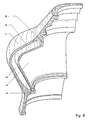
- Figure 2 shows the same embodiment again in a perspective sectional view.
- the curved shape of the outer shell 1 and the inner component 2 with the intermediate Annulus 3 can be seen very well.
- the two are the same axial interfaces 4 through by the outer shell 1 inward circumferential webs are formed, evident. These interfaces 4 are preferred made integrally with the outer shell.
- the outer shell 1 of such a turbine housing can be made very easily with a casting technique become. That separating the hot gas space 5 from the annular space 3 Inner component 2 then only has to be between the two Interfaces 4 are clamped.
- Suitable material differences between the material of the inner component 2 and the material of the outer shell 1 enable an almost temperature-independent Surface pressure of the inner component 2 on the axial Interfaces 4.
- the feeders for the supply of a medium, for example a cooling medium like air, not recognizable in the annular space 3.
- a prescribable pressure can be set via these feeds maintained in the annulus.
Landscapes
- Engineering & Computer Science (AREA)
- Mechanical Engineering (AREA)
- General Engineering & Computer Science (AREA)
- Turbine Rotor Nozzle Sealing (AREA)
- Structures Of Non-Positive Displacement Pumps (AREA)
- Gasket Seals (AREA)
Abstract
Aufgrund dieser Bauweise hält das Turbinengehäuse höheren Verdichterenddrücken und Temperaturen stand und kann auf kostengünstige Weise hergestellt werden.
Description
- Figur 1
- schematisch einen Schnitt durch ein beispielhaftes Turbinengehäuse; und
- Figur 2
- das Turbinengehäuse aus Figur 1 in perspektivischer Schnittansicht.
- 1
- Außenschale
- 2
- Innenbauteil
- 3
- Ringraum
- 4
- Axiale Schnittstelle
- 5
- Heißgasraum
- 6
- Expansionsraum (Turbinenstufe)
- 7
- Verdichterstufe
- 8
- Mittelachse
- 9
- Brennkammerwandung
- 10
- Umgebung
Claims (7)
- Turbinengehäuse für eine axial durchströmte Gasturbine, das zumindest einen Heißgasraum (5) zwischen einer Verdichterstufe (7) und einer Turbinenstufe (6) umschließt und eine Außenschale (1) als äußere Begrenzung sowie ein Innenbauteil (2) aufweist, das den Heißgasraum über einen Zwischenraum (3) von der Außenschale (1) abtrennt,
wobei das Innenbauteil (2) über zwei axiale Schnittstellen (4) derart mit der Außenschale (1) verbunden ist, daß der Zwischenraum (3) gegen den Heißgasraum (5) abgedichtet ist. - Turbinengehäuse nach Anspruch 1,
dadurch gekennzeichnet, daß das Innenbauteil (2) zwischen den axialen Schnittstellen (4) eingespannt ist, so daß die Verbindung mit der Außenschale (1) durch in axialer Richtung wirkende Flächenpressung erfolgt. - Turbinengehäuse nach Anspruch 2,
dadurch gekennzeichnet, daß die Außenschale (1) und das Innenbauteil (2) aus derart unterschiedlichen Werkstoffen gebildet sind, daß sich beim Betrieb der Gasturbine ausreichend Flächenpressung an den axialen Schnittstellen (4) einstellt, um den Zwischenraum (3) gegen den Heißgasraum (5) abzudichten. - Turbinengehäuse nach einem der Ansprüche 1 bis 3,
dadurch gekennzeichnet, daß die axialen Schnittstellen (4) als metallische Dichtflächen ausgebildet sind. - Turbinengehäuse nach einem der Ansprüche 1 bis 4,
dadurch gekennzeichnet, daß Außenschale (1) und Innenbauteil (2) den Heißgasraum (5) ringförmig umschließen. - Turbinengehäuse nach einem der Ansprüche 1 bis 5,
dadurch gekennzeichnet, daß das Innenbauteil (2) eine nach außen gewölbte Form aufweist. - Turbinengehäuse nach einem der Ansprüche 1 bis 6,
dadurch gekennzeichnet, daß die Außenschale (1) eine oder mehrere Öffnungen für die Zufuhr eines Mediums zum Zwischenraum (3) aufweist.
Applications Claiming Priority (2)
| Application Number | Priority Date | Filing Date | Title |
|---|---|---|---|
| DE10016082A DE10016082A1 (de) | 2000-03-31 | 2000-03-31 | Turbinengehäuse für eine axial durchströmte Gasturbine |
| DE10016082 | 2000-03-31 |
Publications (3)
| Publication Number | Publication Date |
|---|---|
| EP1138881A2 true EP1138881A2 (de) | 2001-10-04 |
| EP1138881A3 EP1138881A3 (de) | 2003-10-08 |
| EP1138881B1 EP1138881B1 (de) | 2005-08-03 |
Family
ID=7637141
Family Applications (1)
| Application Number | Title | Priority Date | Filing Date |
|---|---|---|---|
| EP01106613A Expired - Lifetime EP1138881B1 (de) | 2000-03-31 | 2001-03-16 | Turbinengehäuse für eine axial durchströmte Gasturbine |
Country Status (4)
| Country | Link |
|---|---|
| US (1) | US6484511B2 (de) |
| EP (1) | EP1138881B1 (de) |
| CN (1) | CN1320764A (de) |
| DE (2) | DE10016082A1 (de) |
Cited By (2)
| Publication number | Priority date | Publication date | Assignee | Title |
|---|---|---|---|---|
| EP2009250A3 (de) * | 2007-06-29 | 2011-01-05 | General Electric Company | Ringförmiges Turbinengehäuse von einem Gasturbinentriebwerk und entsprechende Turbinenanordnung |
| US8197186B2 (en) | 2007-06-29 | 2012-06-12 | General Electric Company | Flange with axially extending holes for gas turbine engine clearance control |
Families Citing this family (4)
| Publication number | Priority date | Publication date | Assignee | Title |
|---|---|---|---|---|
| SE0300261D0 (sv) * | 2003-01-31 | 2003-01-31 | Electrolux Home Prod Corp | Refrigerator with drawer |
| US7909569B2 (en) * | 2005-06-09 | 2011-03-22 | Pratt & Whitney Canada Corp. | Turbine support case and method of manufacturing |
| US7784261B2 (en) * | 2006-05-25 | 2010-08-31 | Siemens Energy, Inc. | Combined cycle power plant |
| CN109098780B (zh) * | 2018-05-24 | 2024-05-14 | 中车大连机车研究所有限公司 | 一种涡轮增压器燃气废气进排气壳体 |
Citations (1)
| Publication number | Priority date | Publication date | Assignee | Title |
|---|---|---|---|---|
| US5657625A (en) | 1994-06-17 | 1997-08-19 | Mitsubishi Jidosha Kogyo Kabushiki Kaisha | Apparatus and method for internal combustion engine control |
Family Cites Families (10)
| Publication number | Priority date | Publication date | Assignee | Title |
|---|---|---|---|---|
| US2417835A (en) * | 1936-09-25 | 1947-03-25 | Harry H Moore | Combustion device |
| US2575070A (en) * | 1948-04-06 | 1951-11-13 | William A Reed | Jacketed combustion pot with fuel and air nozzle head |
| US2599654A (en) * | 1949-04-04 | 1952-06-10 | Curtiss Wright Corp | Stator blade construction |
| US2702454A (en) * | 1951-06-07 | 1955-02-22 | United Aircraft Corp | Transition piece providing a connection between the combustion chambers and the turbine nozzle in gas turbine power plants |
| US3088281A (en) * | 1956-04-03 | 1963-05-07 | Bristol Siddeley Engines Ltd | Combustion chambers for use with swirling combustion supporting medium |
| US3772881A (en) * | 1970-06-04 | 1973-11-20 | Texaco Ag | Apparatus for controllable in-situ combustion |
| US3842595A (en) * | 1972-12-26 | 1974-10-22 | Gen Electric | Modular gas turbine engine |
| GB2168755B (en) * | 1984-12-08 | 1988-05-05 | Rolls Royce | Improvements in or relating to gas turbine engines |
| JP3564286B2 (ja) * | 1997-12-08 | 2004-09-08 | 三菱重工業株式会社 | ガスタービン静翼の段間シールアクティブクリアランス制御システム |
| DE19821889B4 (de) * | 1998-05-15 | 2008-03-27 | Alstom | Verfahren und Vorrichtung zur Durchführung von Reparatur- und/oder Wartungsarbeiten im Innengehäuse einer mehrschaligen Turbomaschine |
-
2000
- 2000-03-31 DE DE10016082A patent/DE10016082A1/de not_active Withdrawn
-
2001
- 2001-03-16 DE DE50106934T patent/DE50106934D1/de not_active Expired - Fee Related
- 2001-03-16 EP EP01106613A patent/EP1138881B1/de not_active Expired - Lifetime
- 2001-03-28 CN CN01109509A patent/CN1320764A/zh active Pending
- 2001-03-30 US US09/821,090 patent/US6484511B2/en not_active Expired - Fee Related
Patent Citations (1)
| Publication number | Priority date | Publication date | Assignee | Title |
|---|---|---|---|---|
| US5657625A (en) | 1994-06-17 | 1997-08-19 | Mitsubishi Jidosha Kogyo Kabushiki Kaisha | Apparatus and method for internal combustion engine control |
Cited By (3)
| Publication number | Priority date | Publication date | Assignee | Title |
|---|---|---|---|---|
| EP2009250A3 (de) * | 2007-06-29 | 2011-01-05 | General Electric Company | Ringförmiges Turbinengehäuse von einem Gasturbinentriebwerk und entsprechende Turbinenanordnung |
| US8197186B2 (en) | 2007-06-29 | 2012-06-12 | General Electric Company | Flange with axially extending holes for gas turbine engine clearance control |
| US8393855B2 (en) | 2007-06-29 | 2013-03-12 | General Electric Company | Flange with axially curved impingement surface for gas turbine engine clearance control |
Also Published As
| Publication number | Publication date |
|---|---|
| CN1320764A (zh) | 2001-11-07 |
| DE50106934D1 (de) | 2005-09-08 |
| DE10016082A1 (de) | 2001-10-04 |
| EP1138881A3 (de) | 2003-10-08 |
| US6484511B2 (en) | 2002-11-26 |
| EP1138881B1 (de) | 2005-08-03 |
| US20010025479A1 (en) | 2001-10-04 |
Similar Documents
| Publication | Publication Date | Title |
|---|---|---|
| DE60201467T2 (de) | Gasturbinenbrennkammer aus Verbundwerkstoff mit keramischer Matrix | |
| DE60203959T2 (de) | Luftgekühltes Abgasgehäuse für eine Gasturbine | |
| DE60222324T2 (de) | Befestigung von metallischen Aufsätzen auf CMC-Turbomaschinenbrennkammerwänden | |
| EP1631736B1 (de) | Abgasturbine für einen abgasturbolader | |
| EP0991891B1 (de) | Vorrichtung zum verbinden von leitungsabschnitten | |
| EP2655889B1 (de) | Turbomaschinengehäuse mit durch sperrgas abgedichteter teilfuge (bzw. flanschverbindung) | |
| EP3548705B1 (de) | Turbolader | |
| EP3315802A1 (de) | Rotationssystem mit axialer gaslagerung | |
| EP1138881B1 (de) | Turbinengehäuse für eine axial durchströmte Gasturbine | |
| DE602004006656T2 (de) | Gleitringdichtung für drehende Maschinen | |
| EP2396517B1 (de) | Dreischalige dampfturbine | |
| EP3999721B1 (de) | Turbinengehäuse mit einem spannungsarmen verbindungsflansch und abgasturbine mit einem solchen turbinengehäuse | |
| DE3830762A1 (de) | Einrichtung zur halterung eines mantelringes in gasturbinen | |
| EP3571380A1 (de) | Turbinengehäuse und verfahren zur montage einer turbine mit einem turbinengehäuses | |
| CH713701B1 (de) | Turbolader. | |
| EP2474744A1 (de) | Ringförmiger Strömungskanal für einen Axialverdichter | |
| DE102012223462B3 (de) | Backup Dichtung in Kompaktbauweise bei einem Gehäuse einer Strömungsmaschine | |
| EP1933038B1 (de) | Turbomaschinengehäuse | |
| DE102010036071A1 (de) | Gehäuseseitige Struktur einer Turbomaschine | |
| DE202013003855U1 (de) | Untersuchungseinrichtung sowie Multi-Inlet-Vakuumpumpe | |
| DE112023003233T5 (de) | Rotor, Rotationsmaschine und Verfahren zum Zusammenbau eines Rotors | |
| EP2993306B1 (de) | Flugzeugtriebwerk mit luftleitvorrichtung | |
| DE3835341A1 (de) | Kreiselverdichter mit horizontaler teilungsebene | |
| DE3731901C2 (de) | ||
| DE102016202940A1 (de) | Vorrichtung zum Komprimieren oder Expandieren eines Fluids, Verdichter und Turbine |
Legal Events
| Date | Code | Title | Description |
|---|---|---|---|
| PUAI | Public reference made under article 153(3) epc to a published international application that has entered the european phase |
Free format text: ORIGINAL CODE: 0009012 |
|
| AK | Designated contracting states |
Kind code of ref document: A2 Designated state(s): AT BE CH CY DE DK ES FI FR GB GR IE IT LI LU MC NL PT SE TR |
|
| AX | Request for extension of the european patent |
Free format text: AL;LT;LV;MK;RO;SI |
|
| RAP1 | Party data changed (applicant data changed or rights of an application transferred) |
Owner name: ALSTOM POWER N.V. |
|
| RAP1 | Party data changed (applicant data changed or rights of an application transferred) |
Owner name: ALSTOM (SWITZERLAND) LTD |
|
| RAP1 | Party data changed (applicant data changed or rights of an application transferred) |
Owner name: ALSTOM (SWITZERLAND) LTD |
|
| PUAL | Search report despatched |
Free format text: ORIGINAL CODE: 0009013 |
|
| AK | Designated contracting states |
Kind code of ref document: A3 Designated state(s): AT BE CH CY DE DK ES FI FR GB GR IE IT LI LU MC NL PT SE TR |
|
| AX | Request for extension of the european patent |
Extension state: AL LT LV MK RO SI |
|
| RIC1 | Information provided on ipc code assigned before grant |
Ipc: 7F 01D 25/14 B Ipc: 7F 01D 25/26 A |
|
| RAP1 | Party data changed (applicant data changed or rights of an application transferred) |
Owner name: ALSTOM TECHNOLOGY LTD |
|
| 17P | Request for examination filed |
Effective date: 20040320 |
|
| AKX | Designation fees paid |
Designated state(s): DE GB |
|
| 17Q | First examination report despatched |
Effective date: 20040625 |
|
| GRAP | Despatch of communication of intention to grant a patent |
Free format text: ORIGINAL CODE: EPIDOSNIGR1 |
|
| GRAS | Grant fee paid |
Free format text: ORIGINAL CODE: EPIDOSNIGR3 |
|
| GRAA | (expected) grant |
Free format text: ORIGINAL CODE: 0009210 |
|
| AK | Designated contracting states |
Kind code of ref document: B1 Designated state(s): DE GB |
|
| REG | Reference to a national code |
Ref country code: GB Ref legal event code: FG4D Free format text: NOT ENGLISH |
|
| REF | Corresponds to: |
Ref document number: 50106934 Country of ref document: DE Date of ref document: 20050908 Kind code of ref document: P |
|
| GBT | Gb: translation of ep patent filed (gb section 77(6)(a)/1977) |
Effective date: 20050917 |
|
| PGFP | Annual fee paid to national office [announced via postgrant information from national office to epo] |
Ref country code: DE Payment date: 20060314 Year of fee payment: 6 |
|
| PLBE | No opposition filed within time limit |
Free format text: ORIGINAL CODE: 0009261 |
|
| STAA | Information on the status of an ep patent application or granted ep patent |
Free format text: STATUS: NO OPPOSITION FILED WITHIN TIME LIMIT |
|
| 26N | No opposition filed |
Effective date: 20060504 |
|
| GBPC | Gb: european patent ceased through non-payment of renewal fee |
Effective date: 20070316 |
|
| PG25 | Lapsed in a contracting state [announced via postgrant information from national office to epo] |
Ref country code: DE Free format text: LAPSE BECAUSE OF NON-PAYMENT OF DUE FEES Effective date: 20071002 |
|
| PG25 | Lapsed in a contracting state [announced via postgrant information from national office to epo] |
Ref country code: GB Free format text: LAPSE BECAUSE OF NON-PAYMENT OF DUE FEES Effective date: 20070316 |
|
| PGFP | Annual fee paid to national office [announced via postgrant information from national office to epo] |
Ref country code: GB Payment date: 20060322 Year of fee payment: 6 |