EP1138878A2 - Plattenförmiger, auskragender Bauteilabschnitt einer Gasturbine - Google Patents
Plattenförmiger, auskragender Bauteilabschnitt einer Gasturbine Download PDFInfo
- Publication number
- EP1138878A2 EP1138878A2 EP01108008A EP01108008A EP1138878A2 EP 1138878 A2 EP1138878 A2 EP 1138878A2 EP 01108008 A EP01108008 A EP 01108008A EP 01108008 A EP01108008 A EP 01108008A EP 1138878 A2 EP1138878 A2 EP 1138878A2
- Authority
- EP
- European Patent Office
- Prior art keywords
- plenum
- component section
- cooling
- section according
- hot gas
- Prior art date
- Legal status (The legal status is an assumption and is not a legal conclusion. Google has not performed a legal analysis and makes no representation as to the accuracy of the status listed.)
- Granted
Links
Images


Classifications
-
- B—PERFORMING OPERATIONS; TRANSPORTING
- B22—CASTING; POWDER METALLURGY
- B22C—FOUNDRY MOULDING
- B22C9/00—Moulds or cores; Moulding processes
- B22C9/10—Cores; Manufacture or installation of cores
- B22C9/103—Multipart cores
-
- F—MECHANICAL ENGINEERING; LIGHTING; HEATING; WEAPONS; BLASTING
- F01—MACHINES OR ENGINES IN GENERAL; ENGINE PLANTS IN GENERAL; STEAM ENGINES
- F01D—NON-POSITIVE DISPLACEMENT MACHINES OR ENGINES, e.g. STEAM TURBINES
- F01D25/00—Component parts, details, or accessories, not provided for in, or of interest apart from, other groups
- F01D25/08—Cooling; Heating; Heat-insulation
- F01D25/12—Cooling
-
- F—MECHANICAL ENGINEERING; LIGHTING; HEATING; WEAPONS; BLASTING
- F01—MACHINES OR ENGINES IN GENERAL; ENGINE PLANTS IN GENERAL; STEAM ENGINES
- F01D—NON-POSITIVE DISPLACEMENT MACHINES OR ENGINES, e.g. STEAM TURBINES
- F01D5/00—Blades; Blade-carrying members; Heating, heat-insulating, cooling or antivibration means on the blades or the members
- F01D5/12—Blades
- F01D5/14—Form or construction
- F01D5/18—Hollow blades, i.e. blades with cooling or heating channels or cavities; Heating, heat-insulating or cooling means on blades
- F01D5/187—Convection cooling
-
- F—MECHANICAL ENGINEERING; LIGHTING; HEATING; WEAPONS; BLASTING
- F05—INDEXING SCHEMES RELATING TO ENGINES OR PUMPS IN VARIOUS SUBCLASSES OF CLASSES F01-F04
- F05D—INDEXING SCHEME FOR ASPECTS RELATING TO NON-POSITIVE-DISPLACEMENT MACHINES OR ENGINES, GAS-TURBINES OR JET-PROPULSION PLANTS
- F05D2240/00—Components
- F05D2240/80—Platforms for stationary or moving blades
- F05D2240/81—Cooled platforms
-
- F—MECHANICAL ENGINEERING; LIGHTING; HEATING; WEAPONS; BLASTING
- F05—INDEXING SCHEMES RELATING TO ENGINES OR PUMPS IN VARIOUS SUBCLASSES OF CLASSES F01-F04
- F05D—INDEXING SCHEME FOR ASPECTS RELATING TO NON-POSITIVE-DISPLACEMENT MACHINES OR ENGINES, GAS-TURBINES OR JET-PROPULSION PLANTS
- F05D2260/00—Function
- F05D2260/20—Heat transfer, e.g. cooling
- F05D2260/201—Heat transfer, e.g. cooling by impingement of a fluid
-
- F—MECHANICAL ENGINEERING; LIGHTING; HEATING; WEAPONS; BLASTING
- F05—INDEXING SCHEMES RELATING TO ENGINES OR PUMPS IN VARIOUS SUBCLASSES OF CLASSES F01-F04
- F05D—INDEXING SCHEME FOR ASPECTS RELATING TO NON-POSITIVE-DISPLACEMENT MACHINES OR ENGINES, GAS-TURBINES OR JET-PROPULSION PLANTS
- F05D2260/00—Function
- F05D2260/20—Heat transfer, e.g. cooling
- F05D2260/202—Heat transfer, e.g. cooling by film cooling
Definitions
- the invention relates to a plate-shaped, projecting component section of a Gas turbine or the like according to the preamble of claim 1.
- Such component sections can often be found where constructive Overhanging areas on main components, such as on Buckets, fasteners are provided or sealing elements, too between two neighboring components. Problematic are such overhanging component sections especially in thermally highly stressed Areas where hot gas is applied to the surface. It is often essential to provide cooling there.
- EP 0 911 486 A2 describes a cooled one Known blade of a gas turbine, in which overhanging areas in the form of plate-shaped, cantilevered component sections are formed in the axial direction are attached in front of and behind the blade root to cover the hub area with the adjacent blade root areas of rotor blades to ensure.
- To cool this plate-shaped, cantilevered Component sections are provided cooling bores that are purely convective from cooling air be flowed through.
- the cooling holes run for example in the front overhanging component section in the circumferential direction and are from the main cooling air supply fed. Due to the high thermal load in this Area there are additional turbulence generators in the cooling holes, to improve heat transfer.
- the rear, overhanging component section has a plurality of axially extending Cooling holes, which are also fed by the main cooling air supply.
- the cooling bores open axially at the end of the component section, so that the cooling medium escapes into the hot gas stream after flowing through the cooling channels.
- the invention tries to avoid the disadvantages described. You are the Task based on a plate-shaped, projecting component section of a Specify gas turbine or the like of the type mentioned, the one allows more effective cooling of the surface exposed to hot gas and thus has an increased service life with a reduced cooling air requirement.
- a plenum is provided, which is assigned exclusively to the component section, so that enables optimal cooling of the surface exposed to hot gas becomes.
- the plenum is immediately adjacent to the surface to be cooled arranged and is flowed through by the cooling medium convectively.
- the cooling bores are designed as blow-out openings which emanate from the plenum and open on the surface exposed to hot gas. So it is possible, a highly effective film cooling on the hot gas Realize surface, while the coolant consumption is kept extremely low can be. The reason is that the cooling air is initially convective flows through the cooling area and then by blowing out train highly effective cooling film.
- a number of preferred versions are based on the simple and inexpensive Realization of this cooling concept directed.
- the choice of the optimal shaping process for the plenary mainly depends on the manufacturing process from the actual component on which the plate-shaped, projecting section is to be provided. Other important aspects are those to be realized Geometry, as well as the manufacturing specifications.
- a multi-part core is used to create the desired geometry of the plenary. If necessary, side openings for Positioning of the core will be required afterwards, ie afterwards can be concluded from the shaping process.
- the plenum through a recess in the component section to form, for example opposite to the one to be cooled Surface is open and therefore by a cover to be retrofitted can be locked.
- the advantage of this variant lies in the possibility of making the geometry of the plenary largely revealing.
- the cover can be attached using cost-effective connection methods, such as soldering or welding.
- both the plenum and the blow-out openings using the EDM process.
- the shape, size and arrangement of the blow-out openings in particular can be freely selected and implemented with the highest precision.
- the plenum as such can also be implemented exactly with this procedure. Lateral outlet openings, as required for the production of the plenum, can remain completely or partially open as additional outlet openings, depending on the design of the cooling concept. Otherwise, they are closed after the molding process.
- the plenum is preferably connected via feed channels to a main plenum, which supplies the blade with cooling air. In this way, no direct connection to the cooling medium supply is required, which means that the design effort can be reduced.
- cooling concept described above is suitable for use with it is preferred that any thermally highly stressed components can be realized used on overhangs of turbine blades.
- thermal loads particularly high on the other hand is in the immediate vicinity of the overhang mostly provided for a coolant supply anyway, whereby the cooling concept according to the invention is particularly easy to implement leaves.
- the concept according to the invention is based on a plate-shaped, cantilevered Component section explained in the form of an overhang 1, which is a component a platform 3 carrying a turbine blade 4 is formed.
- a surface 2 is thermally highly stressed, namely by one not shown here Hot gas jet.
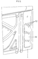
- FIGS. 1 and 2 are on the overhang 1 four essentially parallel and spaced apart Pleni 10 available, which consistently enforce the overhang 1. You run immediately adjacent to the surface 2 and cool it in this area through a cooling medium, which is not shown in more detail and is passed through convectively. Blow-out openings 12 are also present, preferably in rows and arranged in association with the Pleni 10. They are based on Pleni 10 and open on the surface 2. In this way, the cooling medium from the Pleni 10 blown out through the blow-out openings 12 such that a coherent Forms cooling film. The surface 2 is thus optimally cooled.
- the plenums 10 can be operated using EDM tools 19 are formed, drill the through holes in the overhang 1. This creates a connection to a main plenum 5 below the platform 3 manufactured, whereby the pleni 10 are fed with cooling air from this area.
- the plenums 10 can open on the side on the overhang 1, as shown in Fig. 1. In this case, cooling air is also discharged from the side blown out the overhang 1. However, it is equally possible to use Pleni 10 in to partially or completely close this area.
- the cross-section of the individual plenums 10 can vary to match the local one To achieve a coordinated cooling effect when exposed to heat. This also applies to their number and distribution of their arrangement along the overhang 1. The same applies analogously for the cooling bores or blow-out openings 12, which for training of the cooling film are responsible.
- Fig. 3 shows a plenum 30, the overhang 1 largely complete with regard to its longitudinal and transverse extension interspersed throughout. This enables a largely ideally evened out convective cooling of the surface 2 and also offers the possibility of the film cooling air bores (not shown here in detail) are distributed as desired to arrange.
- the plenum 30 is again supplied by the main plenum 5. For this there are feed channels 6 provided that the connection between the main plenum 5 and the Establish plenum 30.
- the plenum 30 and the feed channels 6 are in this case directly during the Casting process formed.
- a core 39 shown in FIG. 4 is used for this purpose, which specifies the shape of the plenum 30.
- FIG. 5 shows a recess 50 cast in the overhang 1, from which the cooling bores 52 depart.
- the actual plenum is then formed when the recess 50 is closed by a cover, not shown here becomes.
- the cover can consist of a simple plate that is on the overhang 1 is placed and soldered or welded there. So you can even complicated geometries due to a corresponding design of the recess 50 are implemented. Such geometries can, for example, on the Surface 2 arranged pins, ribs or turbulence generators (not shown).
Landscapes
- Engineering & Computer Science (AREA)
- Mechanical Engineering (AREA)
- General Engineering & Computer Science (AREA)
- Turbine Rotor Nozzle Sealing (AREA)
Abstract
Description
Bevorzugt ist das Plenum über Speisekanäle mit einem Hauptplenum verbunden, welches die Schaufel mit Kühlluft versorgt. Auf diese Weise ist kein direkter Anschluss an die Kühlmediumversorgung erforderlich, wodurch sich der konstruktive Aufwand reduzieren lässt.
- Fig. 1
- Überhang an einer Turbinenschaufel, perspektivische Ansicht von oben;
- Fig. 2
- Überhang gemäß Fig. 1, Ansicht von unten;
- Fig. 3
- Überhang an einer Turbinenschaufel gemäß einer ersten Ausführungsvariante, Ansicht von unten;
- Fig.4
- Kern zur Herstellung eines Plenums;
- Fig. 5
- Überhang an einer Turbinenschaufel gemäß einer zweiten Ausführungsvariante, Ansicht von unten.
- 1
- Überhang
- 2
- Heißgasseitige Oberfläche
- 3
- Plattform
- 4
- Turbinenschaufel
- 5
- Hauptplenum
- 6
- Speisekanal
- 10
- Plenum, EDM-Bohrung
- 12
- Film-Kühlbohrung, Ausblaseöffnung
- 19
- EDM-Werkzeug
- 30
- Plenum
- 38
- Speisekanalabschnitt
- 39
- Kern
- 50
- Vertiefung
- 52
- Film-Kühlbohrung, Ausblaseöffnung
Claims (9)
- Plattenförmiger, auskragender Bauteilabschnitt einer Gasturbine oder dergleichen, mit einer von Heißgas beaufschlagten Oberfläche und mit Kühlbohrungen, die von einem Kühlmedium durchströmbar sind, dadurch gekennzeichnet, dass wenigstens ein ausschließlich dem Bauteilabschnitt (1) zugeordnetes Plenum (10; 30; 50) vorgesehen ist, das unmittelbar benachbart zu der von Heißgas beaufschlagten Oberfläche (2) angeordnet ist und von dem Kühlmedium konvektiv durchströmbar ist, und dass die Kühlbohrungen als Ausblaseöffnungen (12; 52) ausgebildet sind, die von dem Plenum (10; 30, 50) ausgehen und an der von Heißgas beaufschlagten Oberfläche (2) münden, wodurch ein Kühlfilm generierbar ist.
- Bauteilabschnitt nach Anspruch 1, dadurch gekennzeichnet, dass das Plenum (30, 50) den Bauteilabschnitt (1) weitgehend vollständig durchsetzt.
- Bauteilabschnitt nach Anspruch 1 oder 2, dadurch gekennzeichnet, dass das Plenum (30, 50) im Gießverfahren geformt ist.
- Bauteilabschnitt nach Anspruch 3, dadurch gekennzeichnet, dass das Plenum (30; 50) mittels eines mehrteiligen Kerns (38; 39) gebildet ist.
- Bauteilabschnitt nach einem der Ansprüche 1 bis 4, dadurch gekennzeichnet, dass das Plenum (30; 50) durch eine in den Bauteilabschnitt (1) eingeformte Vertiefung (50) gebildet ist, die durch eine Abdeckung verschlossen ist.
- Bauteilabschnitt nach Anspruch 5, dadurch gekennzeichnet, dass die Abdeckung mit dem Bauteilabschnitt (1) verlötet oder verschweißt ist.
- Bauteilabschnitt nach Anspruch 1 oder 2, dadurch gekennzeichnet, dass das Plenum (10) und/oder die Ausblaseöffnungen (12) im EDM-Verfahren hergestellt ist/sind.
- Bauteilabschnitt nach einem der vorhergehenden Ansprüche, dadurch gekennzeichnet, dass das Plenum (10; 30; 50) über Speisekanäle (6) mit einem Hauptplenum (5) verbunden ist.
- Bauteilabschnitt nach einem der vorhergehenden Ansprüche in Form eines an einer Turbinenschaufel (4) gebildeten Überhangs (1).
Applications Claiming Priority (2)
| Application Number | Priority Date | Filing Date | Title |
|---|---|---|---|
| DE10016081A DE10016081A1 (de) | 2000-03-31 | 2000-03-31 | Plattenförmiger, auskragender Bauteilabschnitt einer Gasturbine |
| DE10016081 | 2000-03-31 |
Publications (3)
| Publication Number | Publication Date |
|---|---|
| EP1138878A2 true EP1138878A2 (de) | 2001-10-04 |
| EP1138878A3 EP1138878A3 (de) | 2003-10-01 |
| EP1138878B1 EP1138878B1 (de) | 2008-05-14 |
Family
ID=7637140
Family Applications (1)
| Application Number | Title | Priority Date | Filing Date |
|---|---|---|---|
| EP01108008A Expired - Lifetime EP1138878B1 (de) | 2000-03-31 | 2001-03-29 | Bauteil einer Gasturbine |
Country Status (3)
| Country | Link |
|---|---|
| US (1) | US6565317B2 (de) |
| EP (1) | EP1138878B1 (de) |
| DE (2) | DE10016081A1 (de) |
Cited By (2)
| Publication number | Priority date | Publication date | Assignee | Title |
|---|---|---|---|---|
| CH700320A1 (de) * | 2009-01-30 | 2010-07-30 | Alstom Technology Ltd | Verfahren zum herstellen eines bauteils einer gasturbine. |
| EP3467257A1 (de) * | 2017-10-09 | 2019-04-10 | United Technologies Corporation | Leitschaufelplattform-kühlstrukturen |
Families Citing this family (7)
| Publication number | Priority date | Publication date | Assignee | Title |
|---|---|---|---|---|
| US6887033B1 (en) * | 2003-11-10 | 2005-05-03 | General Electric Company | Cooling system for nozzle segment platform edges |
| US7004720B2 (en) * | 2003-12-17 | 2006-02-28 | Pratt & Whitney Canada Corp. | Cooled turbine vane platform |
| US7625172B2 (en) * | 2006-04-26 | 2009-12-01 | United Technologies Corporation | Vane platform cooling |
| US10189100B2 (en) | 2008-07-29 | 2019-01-29 | Pratt & Whitney Canada Corp. | Method for wire electro-discharge machining a part |
| US8925201B2 (en) * | 2009-06-29 | 2015-01-06 | Pratt & Whitney Canada Corp. | Method and apparatus for providing rotor discs |
| US20130094971A1 (en) * | 2011-10-12 | 2013-04-18 | General Electric Company | Hot gas path component for turbine system |
| CA2898822A1 (en) | 2013-03-13 | 2014-10-09 | Rolls-Royce Corporation | Trenched cooling hole arrangement for a ceramic matrix composite vane |
Citations (1)
| Publication number | Priority date | Publication date | Assignee | Title |
|---|---|---|---|---|
| EP0911486A2 (de) | 1997-10-28 | 1999-04-28 | Mitsubishi Heavy Industries, Ltd. | Kühlung einer Gasturbinenleitschaufel |
Family Cites Families (11)
| Publication number | Priority date | Publication date | Assignee | Title |
|---|---|---|---|---|
| IT1079131B (it) * | 1975-06-30 | 1985-05-08 | Gen Electric | Perfezionato raffreddamento applicabile particolarmente a elementi di turbomotori a gas |
| US4017213A (en) * | 1975-10-14 | 1977-04-12 | United Technologies Corporation | Turbomachinery vane or blade with cooled platforms |
| DE2643049A1 (de) * | 1975-10-14 | 1977-04-21 | United Technologies Corp | Schaufel mit gekuehlter plattform fuer eine stroemungsmaschine |
| US4353679A (en) * | 1976-07-29 | 1982-10-12 | General Electric Company | Fluid-cooled element |
| GB2163218B (en) * | 1981-07-07 | 1986-07-16 | Rolls Royce | Cooled vane or blade for a gas turbine engine |
| JPH03213602A (ja) * | 1990-01-08 | 1991-09-19 | General Electric Co <Ge> | ガスタービンエンジンの当接セグメントを連結する自己冷却式ジョイント連結構造 |
| US5197852A (en) * | 1990-05-31 | 1993-03-30 | General Electric Company | Nozzle band overhang cooling |
| GB9224241D0 (en) * | 1992-11-19 | 1993-01-06 | Bmw Rolls Royce Gmbh | A turbine blade arrangement |
| US5344283A (en) * | 1993-01-21 | 1994-09-06 | United Technologies Corporation | Turbine vane having dedicated inner platform cooling |
| US5413458A (en) * | 1994-03-29 | 1995-05-09 | United Technologies Corporation | Turbine vane with a platform cavity having a double feed for cooling fluid |
| US5823741A (en) * | 1996-09-25 | 1998-10-20 | General Electric Co. | Cooling joint connection for abutting segments in a gas turbine engine |
-
2000
- 2000-03-31 DE DE10016081A patent/DE10016081A1/de not_active Withdrawn
-
2001
- 2001-03-29 DE DE50113955T patent/DE50113955D1/de not_active Expired - Lifetime
- 2001-03-29 EP EP01108008A patent/EP1138878B1/de not_active Expired - Lifetime
- 2001-03-30 US US09/820,679 patent/US6565317B2/en not_active Expired - Lifetime
Patent Citations (1)
| Publication number | Priority date | Publication date | Assignee | Title |
|---|---|---|---|---|
| EP0911486A2 (de) | 1997-10-28 | 1999-04-28 | Mitsubishi Heavy Industries, Ltd. | Kühlung einer Gasturbinenleitschaufel |
Cited By (5)
| Publication number | Priority date | Publication date | Assignee | Title |
|---|---|---|---|---|
| CH700320A1 (de) * | 2009-01-30 | 2010-07-30 | Alstom Technology Ltd | Verfahren zum herstellen eines bauteils einer gasturbine. |
| WO2010086402A2 (de) | 2009-01-30 | 2010-08-05 | Alstom Technology Ltd. | Verfahren zum herstellen eines bauteils einer gasturbine |
| WO2010086402A3 (de) * | 2009-01-30 | 2010-10-21 | Alstom Technology Ltd. | Verfahren zum herstellen eines bauteils einer gasturbine |
| EP3467257A1 (de) * | 2017-10-09 | 2019-04-10 | United Technologies Corporation | Leitschaufelplattform-kühlstrukturen |
| US11118474B2 (en) | 2017-10-09 | 2021-09-14 | Raytheon Technologies Corporation | Vane cooling structures |
Also Published As
| Publication number | Publication date |
|---|---|
| EP1138878B1 (de) | 2008-05-14 |
| EP1138878A3 (de) | 2003-10-01 |
| US6565317B2 (en) | 2003-05-20 |
| US20010036407A1 (en) | 2001-11-01 |
| DE10016081A1 (de) | 2001-10-04 |
| DE50113955D1 (de) | 2008-06-26 |
Similar Documents
| Publication | Publication Date | Title |
|---|---|---|
| DE3211139C1 (de) | Axialturbinenschaufel,insbesondere Axialturbinenlaufschaufel fuer Gasturbinentriebwerke | |
| DE10001109B4 (de) | Gekühlte Schaufel für eine Gasturbine | |
| EP1013884B1 (de) | Turbinenschaufel mit aktiv gekühltem Deckbandelememt | |
| DE19944923B4 (de) | Turbinenschaufel für den Rotor einer Gasturbine | |
| DE60018817T2 (de) | Gekühlte Gasturbinenschaufel | |
| EP2384392B2 (de) | Gekühltes bauelement für eine gasturbine | |
| DE69011005T2 (de) | Keramischer Gasbrenner für Heisslufterhitzer und Steine dafür. | |
| DE60017166T2 (de) | Gusskern für eine innengekühlte turbinenschaufel, deren speiseröffnung nicht verschlossen werden muss | |
| EP1113145B1 (de) | Schaufel für Gasturbinen mit Drosselquerschnitt an Hinterkante | |
| DE69823236T2 (de) | Einrichtung zur kühlung von gasturbinenschaufeln und methode zu deren herstellung | |
| DE19810066C2 (de) | Gasturbinenlaufschaufel | |
| DE60128319T2 (de) | Mantelringsegment für eine Turbine | |
| DE60223115T2 (de) | Kühlfluidführung bei einem Gasturbinenschaufelblatt | |
| EP2304185B1 (de) | Turbinenschaufel für eine gasturbine und gusskern zum herstellen in einer solchen | |
| DE60221284T2 (de) | Bauteil zur beaufschlagung mit hoher thermischer belastung beim betrieb und verfahren zur herstellung eines solchen bauteils | |
| DE102009026052B4 (de) | Kühleinrichtung für das hintere Ende eines Brennkammerübergangstücks und zugehöriges Verfahren | |
| DE69914509T2 (de) | Verfahren zur Herstellung einer dreiteiligen Spritzgiessdüse und eines Spritzgiesshohlraumeinsatzes und zum Kühlen eines Formhohlraumes | |
| EP2611990B1 (de) | Turbinenschaufel für eine gasturbine | |
| CH628397A5 (de) | Luftgekuehlte turbinenschaufel. | |
| EP1211384A2 (de) | Verfahren zum Einbringen eines gekrümmten Kühlkanals in eine Gasturbinenkomponente sowie kühlbare Schaufel für eine Gasturbinenkomponente | |
| EP1247602B1 (de) | Verfahren zur Herstellung einer Turbinenschaufel | |
| EP1431662B1 (de) | Geschlossen gekühlte Brennkammer für eine Turbine | |
| EP1668236A1 (de) | Brennkammer mit kühleinrichtung und verfahren zur herstellung der brennkammer | |
| EP1138878A2 (de) | Plattenförmiger, auskragender Bauteilabschnitt einer Gasturbine | |
| WO2010028913A1 (de) | Turbinenschaufel mit einer modularen, gestuften hinterkante |
Legal Events
| Date | Code | Title | Description |
|---|---|---|---|
| PUAI | Public reference made under article 153(3) epc to a published international application that has entered the european phase |
Free format text: ORIGINAL CODE: 0009012 |
|
| AK | Designated contracting states |
Kind code of ref document: A2 Designated state(s): AT BE CH CY DE DK ES FI FR GB GR IE IT LI LU MC NL PT SE TR |
|
| AX | Request for extension of the european patent |
Free format text: AL;LT;LV;MK;RO;SI |
|
| RAP1 | Party data changed (applicant data changed or rights of an application transferred) |
Owner name: ALSTOM (SWITZERLAND) LTD |
|
| RAP1 | Party data changed (applicant data changed or rights of an application transferred) |
Owner name: ALSTOM (SWITZERLAND) LTD |
|
| PUAL | Search report despatched |
Free format text: ORIGINAL CODE: 0009013 |
|
| AK | Designated contracting states |
Kind code of ref document: A3 Designated state(s): AT BE CH CY DE DK ES FI FR GB GR IE IT LI LU MC NL PT SE TR |
|
| AX | Request for extension of the european patent |
Extension state: AL LT LV MK RO SI |
|
| RAP1 | Party data changed (applicant data changed or rights of an application transferred) |
Owner name: ALSTOM TECHNOLOGY LTD |
|
| 17P | Request for examination filed |
Effective date: 20040320 |
|
| AKX | Designation fees paid |
Designated state(s): DE GB |
|
| 17Q | First examination report despatched |
Effective date: 20040729 |
|
| 17Q | First examination report despatched |
Effective date: 20040812 |
|
| GRAP | Despatch of communication of intention to grant a patent |
Free format text: ORIGINAL CODE: EPIDOSNIGR1 |
|
| RTI1 | Title (correction) |
Free format text: GAS TURBINE COMPONENT |
|
| GRAS | Grant fee paid |
Free format text: ORIGINAL CODE: EPIDOSNIGR3 |
|
| GRAA | (expected) grant |
Free format text: ORIGINAL CODE: 0009210 |
|
| RIN1 | Information on inventor provided before grant (corrected) |
Inventor name: RICHTER, MARK Inventor name: BEECK, ALEXANDER, DR. Inventor name: SEMMLER, KLAUS Inventor name: STENGELE, JOERG, DR. Inventor name: NAGLER, CHRISTOPH Inventor name: SCHNEIDER, LOTHAR |
|
| AK | Designated contracting states |
Kind code of ref document: B1 Designated state(s): DE GB |
|
| REG | Reference to a national code |
Ref country code: GB Ref legal event code: FG4D Free format text: NOT ENGLISH |
|
| RIN1 | Information on inventor provided before grant (corrected) |
Inventor name: STENGELE, JOERG, DR. Inventor name: BEECK, ALEXANDER, DR. Inventor name: SEMMLER, KLAUS Inventor name: SCHNEIDER, LOTHAR Inventor name: NAGLER, CHRISTOPH Inventor name: RICHTER, MARK |
|
| REF | Corresponds to: |
Ref document number: 50113955 Country of ref document: DE Date of ref document: 20080626 Kind code of ref document: P |
|
| PLBE | No opposition filed within time limit |
Free format text: ORIGINAL CODE: 0009261 |
|
| STAA | Information on the status of an ep patent application or granted ep patent |
Free format text: STATUS: NO OPPOSITION FILED WITHIN TIME LIMIT |
|
| 26N | No opposition filed |
Effective date: 20090217 |
|
| REG | Reference to a national code |
Ref country code: DE Ref legal event code: R082 Ref document number: 50113955 Country of ref document: DE Representative=s name: ROESLER, UWE, DIPL.-PHYS.UNIV., DE Ref country code: DE Ref legal event code: R081 Ref document number: 50113955 Country of ref document: DE Owner name: GENERAL ELECTRIC TECHNOLOGY GMBH, CH Free format text: FORMER OWNER: ALSTOM TECHNOLOGY LTD., BADEN, CH Ref country code: DE Ref legal event code: R081 Ref document number: 50113955 Country of ref document: DE Owner name: ANSALDO ENERGIA IP UK LIMITED, GB Free format text: FORMER OWNER: ALSTOM TECHNOLOGY LTD., BADEN, CH |
|
| PGFP | Annual fee paid to national office [announced via postgrant information from national office to epo] |
Ref country code: DE Payment date: 20170322 Year of fee payment: 17 |
|
| PGFP | Annual fee paid to national office [announced via postgrant information from national office to epo] |
Ref country code: GB Payment date: 20170322 Year of fee payment: 17 |
|
| REG | Reference to a national code |
Ref country code: DE Ref legal event code: R082 Ref document number: 50113955 Country of ref document: DE Representative=s name: ROESLER, UWE, DIPL.-PHYS.UNIV., DE Ref country code: DE Ref legal event code: R081 Ref document number: 50113955 Country of ref document: DE Owner name: ANSALDO ENERGIA IP UK LIMITED, GB Free format text: FORMER OWNER: GENERAL ELECTRIC TECHNOLOGY GMBH, BADEN, CH |
|
| REG | Reference to a national code |
Ref country code: GB Ref legal event code: 732E Free format text: REGISTERED BETWEEN 20170824 AND 20170830 |
|
| REG | Reference to a national code |
Ref country code: DE Ref legal event code: R119 Ref document number: 50113955 Country of ref document: DE |
|
| GBPC | Gb: european patent ceased through non-payment of renewal fee |
Effective date: 20180329 |
|
| PG25 | Lapsed in a contracting state [announced via postgrant information from national office to epo] |
Ref country code: DE Free format text: LAPSE BECAUSE OF NON-PAYMENT OF DUE FEES Effective date: 20181002 |
|
| PG25 | Lapsed in a contracting state [announced via postgrant information from national office to epo] |
Ref country code: GB Free format text: LAPSE BECAUSE OF NON-PAYMENT OF DUE FEES Effective date: 20180329 |