EP0911486A2 - Kühlung einer Gasturbinenleitschaufel - Google Patents
Kühlung einer Gasturbinenleitschaufel Download PDFInfo
- Publication number
- EP0911486A2 EP0911486A2 EP98120025A EP98120025A EP0911486A2 EP 0911486 A2 EP0911486 A2 EP 0911486A2 EP 98120025 A EP98120025 A EP 98120025A EP 98120025 A EP98120025 A EP 98120025A EP 0911486 A2 EP0911486 A2 EP 0911486A2
- Authority
- EP
- European Patent Office
- Prior art keywords
- passage
- leading edge
- cooling
- cooling air
- air
- Prior art date
- Legal status (The legal status is an assumption and is not a legal conclusion. Google has not performed a legal analysis and makes no representation as to the accuracy of the status listed.)
- Granted
Links
Images


Classifications
-
- F—MECHANICAL ENGINEERING; LIGHTING; HEATING; WEAPONS; BLASTING
- F01—MACHINES OR ENGINES IN GENERAL; ENGINE PLANTS IN GENERAL; STEAM ENGINES
- F01D—NON-POSITIVE DISPLACEMENT MACHINES OR ENGINES, e.g. STEAM TURBINES
- F01D5/00—Blades; Blade-carrying members; Heating, heat-insulating, cooling or antivibration means on the blades or the members
- F01D5/12—Blades
- F01D5/14—Form or construction
- F01D5/18—Hollow blades, i.e. blades with cooling or heating channels or cavities; Heating, heat-insulating or cooling means on blades
- F01D5/187—Convection cooling
- F01D5/188—Convection cooling with an insert in the blade cavity to guide the cooling fluid, e.g. forming a separation wall
- F01D5/189—Convection cooling with an insert in the blade cavity to guide the cooling fluid, e.g. forming a separation wall the insert having a tubular cross-section, e.g. airfoil shape
-
- F—MECHANICAL ENGINEERING; LIGHTING; HEATING; WEAPONS; BLASTING
- F01—MACHINES OR ENGINES IN GENERAL; ENGINE PLANTS IN GENERAL; STEAM ENGINES
- F01D—NON-POSITIVE DISPLACEMENT MACHINES OR ENGINES, e.g. STEAM TURBINES
- F01D9/00—Stators
- F01D9/06—Fluid supply conduits to nozzles or the like
- F01D9/065—Fluid supply or removal conduits traversing the working fluid flow, e.g. for lubrication-, cooling-, or sealing fluids
-
- F—MECHANICAL ENGINEERING; LIGHTING; HEATING; WEAPONS; BLASTING
- F05—INDEXING SCHEMES RELATING TO ENGINES OR PUMPS IN VARIOUS SUBCLASSES OF CLASSES F01-F04
- F05B—INDEXING SCHEME RELATING TO WIND, SPRING, WEIGHT, INERTIA OR LIKE MOTORS, TO MACHINES OR ENGINES FOR LIQUIDS COVERED BY SUBCLASSES F03B, F03D AND F03G
- F05B2240/00—Components
- F05B2240/80—Platforms for stationary or moving blades
- F05B2240/801—Platforms for stationary or moving blades cooled platforms
-
- F—MECHANICAL ENGINEERING; LIGHTING; HEATING; WEAPONS; BLASTING
- F05—INDEXING SCHEMES RELATING TO ENGINES OR PUMPS IN VARIOUS SUBCLASSES OF CLASSES F01-F04
- F05D—INDEXING SCHEME FOR ASPECTS RELATING TO NON-POSITIVE-DISPLACEMENT MACHINES OR ENGINES, GAS-TURBINES OR JET-PROPULSION PLANTS
- F05D2240/00—Components
- F05D2240/80—Platforms for stationary or moving blades
- F05D2240/81—Cooled platforms
Definitions
- the present invention relates to a gas turbine stationary blade, and more specifically to a gas turbine stationary blade having a cooling structure for applying air cooling to a second stage stationary blade with a high cooling efficiency.
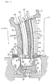
- Fig. 1 a cross sectional view of a typical structure of gas turbine is shown and an outline thereof will be described first.
- numeral 1 designates a compressor portion
- numeral 2 designates a combustor portion
- numeral 3 designates a turbine portion.
- Numeral 4 designates a rotor, which extends in a turbine axial direction from the compressor portion 1 to the turbine portion 3.
- Numeral 6 designates an inner housing and numerals 7, 8 designate cylinders of compressor portion 1, which surround an outer circumference of a compressor.
- Numeral 9 designates a cylindrical shell forming a chamber
- numeral 10 designates an outer shell of the turbine portion 3
- numeral 11 designates an inner shell of same
- numeral 12 designates a stationary blade of compressor and a plurality of the stationary blades are disposed along a compressor circumferential direction with equal spacing between each of the blades and in multi-stage along a compressor axial direction
- numeral 13 designates a moving blade of compressor and a plurality of the moving blades are fixed around the rotor 4 and disposed alternately with the stationary blades 12 along the compressor axial direction.
- Numeral 14 designates a chamber surrounded by the cylindrical shell 9 and numeral 15 designates a combustor, disposed in the chamber 14, into which fuel 35 is injected from a fuel nozzle 34 for combustion.
- Numeral 16 designates a duct for leading a high temperature combustion gas 30 generated in the combustor 15 into the turbine portion 3.
- Numeral 17 designates a second stage stationary blade of gas turbine, which is the object of the present invention. In the case shown in Fig. 1, the gas turbine is constructed of four stage stationary blades and four stage moving blades disposed alternately therewith, and the high temperature combustion gas 30 passes through the blades and is discharged as an expanded gas 31.
- Numeral 21 designates a manifold of the compressor portion 1 and numeral 22 designates a manifold of the turbine portion 3 and cooling air is supplied from the manifold 21 of the compressor portion 1 to the manifold 22 of the turbine portion via a pipe 32 and an air piping 19.
- the fuel 35 is injected into the combustor 15 from the fuel nozzle 34 to be burnt to generate the high temperature combustion gas 30 and then flows into the turbine portion 3 to pass through a passage where the stationary blades and the moving blades are disposed alternately and to expand to rotate the moving blades and the rotor 4 and is discharged as the expanded gas 31.
- Fig. 6 is a cross sectional view of the second stage stationary blade 17 of the prior art gas turbine, said stationary blade being cut along a turbine axial direction at approximately a central portion of its inner shroud and seen from an inner side thereof, that is, on a rotor 4 side
- Fig. 7 is a cross sectional view taken on line D-D of Fig. 6
- Fig. 8 is a cross sectional view taken on line E-E of Fig. 6
- Fig. 9 is a cross sectional view taken on line F-F of Fig. 6
- Fig. 10 is a cross sectional view taken on line G-G of Fig. 6
- Fig. 11 is a cross sectional view taken on line H-H of Fig. 6
- Fig. 12 is a cross sectional view taken on line J-J of Fig. 6.
- numeral 26 designates an inner shroud and therein provided are a rib 40, and a leading edge passage 42 and a trailing edge passage 44 mutually separated by the rib 40, and a projection portion 95 provided therearound.
- Numerals 96, 97 designate rails of both side edge portions of the inner shroud 26 and numerals 93, 94 designate passages of cooling air provided in the rails 96, 97, respectively.
- a passage 88 is provided in an leading edge portion 41 of the inner shroud 26 and a multiplicity of passages 92 are provided in a trailing edge portion 43 of the inner shroud 26.
- Numeral 100 designates a recess portion formed by the projection portion 95 and numerals 83, 84 designate impingement plates, each having a multiplicity of small holes 101 provided therein as passages of air.
- Numerals 81, 82 designate a front flange and a rear flange, respectively, and there are provided passages 90, 91 in the front flange 81.
- Cooling air 57 which has entered the recess portion 100 passes through the passage 90 in the front flange 81 and the passage 88 in the leading edge portion 41 and then through the passage 91 in the front flange 81 and enters a chamber formed by the impingement plate 83.
- a portion 58 of the cooling air which has entered the passage 88 passes through the passages 93, 94 in the rails 96, 97 of the side edge portions for cooling therearound and is discharged outside as a cooling air 61.
- the cooling air which has flown through the small holes 101 of the impinge plates 83, 84 and the cooling air which has flown through the passage 91 gather together in the chamber to further flow through the multiplicity of passages 92 of the trailing edge portion 43 and to be discharged outside as a cooling air 60.
- Fig. 7 being a cross sectional view taken on line D-D of Fig. 6, the passage 88 is formed in the leading edge portion 41 of the inner shroud 26 and the multiplicity of needle-like fins 89 are provided therein.
- the recess portion 100 in the front of the projection portion 95 and a recess portion 99 in the rear of same.
- the impingement plate 84 is provided so as to form the chamber 78 on an outer side of the impingement plate 84.
- a passage 90 which connects to the passage 88 and a portion 57 of the cooling air, flowing through the passages 90 and 88, and another portion 59 of the cooling air, passing through the small holes 101 of the impingement plate 84, gather together in the chamber 78 to further flow through the multiplicity of passages 92 of the trailing edge portion 43 and is then discharged as the cooling air 60.
- the second stage stationary blade 17 has the inner shroud 26 and the outer shroud 27 and a blade portion 25 is formed therebetween.
- the leading edge passage 42 in front of the rib 40 and the trailing edge passage 44 in the rear of same are formed between a leading edge portion 28 and a trailing edge portion 29 of the blade portion 25 and cylindrical members 46, 47 are inserted into these passages 42, 44, respectively.
- the passage 88 and the needle-like fins 89 in the passage 88 are provided, and in the trailing edge portion 43 of the inner shroud 26, the passages 92 are provided so as to connect to a cavity 45 which is formed by the front and rear flanges 81, 82 and a seal support portion 66.
- a chamber 77 is formed by the impingement plate 84 in the cavity 45.
- the seal support portion 66 supports a seal 33, by which a seal mechanism between the inner shroud 26 and rotor side arm portions 48 is constructed.
- Cooling air 19' from the air piping 19 flows into the cylindrical members 46, 47 to be injected through the cooling air holes 70, 71 to impinge on walls of the leading edge passage 42 and the trailing edge passage 44 and to flow toward the inner side thereof as well as to be injected through the cooling air holes 72, 73 of the bottom walls of the cylindrical members 46, 47 to flow into opening portions 68, 69 and then the cooling air as shown by numerals 75, 76 flows into the cavity 45.
- the cooling air then flows into a space between the inner shroud 26 and a front stage moving blade thereof and a space between the inner shroud 26 and a rear stage moving blade thereof via the seal 33 to thereby maintain said spaces in a higher pressure than in a passage of the high temperature combustion gas 30 and to prevent the high temperature combustion gas 30 from coming into said spaces.
- a recess portion 98 and the chamber 77 are formed by the impingement plate 83 between the front flange 81 and the rear flange 82, and the passage 91 provided in the front flange 81 connects to the passage 88 and the passages 92 provided in the trailing edge portion 43 connect to the chamber 77.
- Cooling air 59 in the cavity 45 is injected into the chamber 77 through the small holes 101 of the impingement plate 83 for cooling therearound, as shown by arrows of the air 59.
- cooling air which has flown through the passage 88 enters the passage 91 of the front flange 81 to join with the cooling air 59 in the chamber 77 both to be then discharged as the cooling air 60 through the passages 92 of the trailing edge portion 43.
- Fig. 10 being a cross sectional view taken on line G-G of Fig. 6, the recess portions 98, 99 are provided around the blade portion 25 and the passages 93, 94 are provided in the rails 96, 97, respectively. Also, the chambers 77, 78 are formed by the impingement plates 83, 84, respectively. Cooling air 75 flows into the cavity 45 from the leading edge passage 42 and flows therefrom into the chambers 77, 78 through the small holes 101 of the impingement plates 83, 84.
- Fig. 11 being a cross sectional view taken on line H-H of Fig. 6, the passages 90, 91 of the front flange 81 and the passages 93, 94 of the side edge portions are provided in both of the side edge portions of the inner shroud 26 and the passages 90, 91 connect respectively to the passage 88 of the leading edge portion 41.
- Fig. 12 being a cross sectional view taken on line J-J of Fig. 6, the passage 94 of the rail 97 is provided extending through the trailing edge portion 43 so that the cooling air 61 is discharged therefrom and the impingement plate 83 is provided between the front flange 81 and the rear flange 82.
- the cooling air 57 from the recess portion 100 flows into the passage 88 of the leading edge portion 41 through the passage 90 of the front flange 81.
- the multiplicity of needle-like fins 99 in the passage 88 thereby cooling effect of the cooling air 57 is enhanced so that portions therearound are cooled efficiently.
- the cooling air 57 bends approximately orthogonally at the passage 91 and flows into the chamber 77 formed by the impingement plate 83 to join with the cooling air flowing thereinto through the small holes 101 of the impingement plate 83 and flows together through the trailing edge portion 43 for cooling thereof and is discharged through the passages 92.
- the cooling air which has been injected through the small holes 101 of the impingement plate 84 to enter the chamber 78 is likewise discharged through the passages 92.
- the portion 58 of the air which has entered the passage 88 passes through the passages 93, 94 in the rails 96, 97, respectively, of the side edge portions for cooling therearound and are discharged as the cooling air 61 from the trailing edge portion 43.
- the cooling air 75, 76 in the cavity 45 is portioned to be made effective use thereof respectively to flow through the passage 88, of which heat transfer is enhanced by the needle-like fins 89, the passages 93, 94 in the rails 96, 97 and the multiplicity of passages 92 in the trailing edge portion 43, thereby entire cooling of the inner shroud 26 is aimed to be performed efficiently.
- the cooling air passes through the passage 88 and the needle-like fins 89 provided therein for enhancement of the cooling effect to further flow portionally into the chamber 77 formed by the impingement plate 83 through the passage 91 of the front flange 81 and also the cooling air is injected into the chambers 77, 78 through the small holes 101 of the impingement plates 83, 84 for cooling of the central portion and then both the cooling air joins together to flow through the multiplicity of passages 92 of the trailing edge portion 43 for cooling therearound and further the cooling air from the passage 88 of the leading edge portion 41 portionally flows through the passages 93, 94 of the rails 96, 97 of the side edge portions for cooling therearound.
- the cooling air entering the passage 88 of the leading edge portion 41 is a part of the cooling air entering the cavity 45 and comes from the recess portion 100 through the passage 90 and in order to further enhance the cooling effect of the leading edge portion 41, it is expected that amount of the cooling air flowing therein and flow velocity thereof are increased so as to enhance the cooling effect further.
- an object of the present invention to provide a gas turbine stationary blade in which an entire cooling effect of inner shroud is further enhanced by a construction made such that amount of cooling air entering a leading edge portion and flow velocity thereof are increased with cooling effect thereof being further enhanced by agitation of the cooling air and also cooling air flowing in both side edge portions is increased.
- the present invention provides following means mentioned in (1) to (3):
- the cooling air which has flown through the leading edge side passage for cooling the blade interior enters in its entire amount into the passage of the leading edge portion of the inner shroud for cooling of the leading edge portion and then is separated to flow into the passages of the side edge portions.
- the cooling air which has flown through the passages of the side edge portions for cooling thereof enters the trailing edge portion for cooling thereof and is then discharged outside.
- the entire amount of the cooling air which has flown through the leading edge side passage for cooling of the blade interior enters the passage of the leading edge portion so that the leading edge portion which is exposed to a high temperature combustion gas and is in a severe temperature condition is cooled efficiently.
- the cooling air in the passage of the leading edge portion is then separated to flow through the respective side edge portions, thereby the side edge portions which are also exposed to the high temperature combustion gas are cooled efficiently. Then, the cooling air is discharged out of the trailing edge portion.
- the cooling air from the trailing edge side passage enters the central portion of the inner shroud to spread therearound for cooling the central portion and then is discharged outside through the trailing edge portion.
- the construction is such that the cooling air to enter the leading edge portion once flows into a cavity to be then portionally flown to be used as a seal air and portionally flown into the leading edge portion to be used as a cooling air thereof, but in the present invention, the entire amount of the cooling air from the leading edge side passage flows directly into the leading edge portion, hence the air of high pressure can be supplied as it is with an increased amount of the air as compared with the prior art case.
- the cooling air which has flown into the leading edge portion in the prior art case further flows portionally into the central portion of the inner shroud, but in the invention mentioned in (1) above, there is eliminated the passage connecting from the leading edge portion to the central portion and the entire amount of the air in the passage of the leading edge portion flows separatedly into the side edge portions, hence the leading edge portion and the side edge portions, both being in the severe temperature condition, are cooled efficiently as compared with the prior art case.
- the flow passage cross sectional area of the leading edge portion is made narrower appropriately by the adjusting plate, hence the flow velocity of the cooling air therein is increased.
- the turbulators are provided, hence the cooling effect of the leading edge portion is increased greatly by the agitating action of the turbulators as compared with the prior art case.
- the present invention relates to a gas turbine stationary blade, and more specifically to a cooling structure of inner shroud of a second stage stationary blade of gas turbine.
- Fig. 1 is an entire cross sectional view of a gas turbine and a second stage stationary blade 17 shown there is the object of the present invention. Structure of other portions than the second stage stationary blade 17 of the present invention is same as that described in the column of the prior art with repeated description thereof being omitted here and featured portion of the present invention will be described with reference to Figs. 2 to 5.
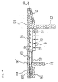
- Fig. 2 is a cross sectional view of the second stage stationary blade 17 which is cut along a turbine axial direction at approximately a central portion of its inner shroud 126 and seen from an inner side thereof, that is, on a rotor side.
- a rib 40 at a central portion, and a leading edge passage 42 and a trailing edge passage 44 mutually separated by the rib 40, and impingement plates 83, 84 therearound having a multiplicity of small holes 101.
- a passage 188 which connects to a passage 90' provided in the front flange 81 so as to lead a cooling air thereinto.
- the passage 188 has a width of flow passage which is narrower than the prior art one, as described later, and has a plurality of turbulators 200 provided therein for enhancing further an agitating effect of internal air flow than the prior art needle-like fins.
- a bottom plate 150 is provided at a bottom portion of the leading edge passage 42, so that entire amount of the cooling air flowing from the leading edge passage 42 flows into the passage 188 through the passage 90'.
- the cooling air of higher pressure can be supplied directly from the leading edge passage 42 and both the flow amount and the flow velocity of the air can be increased.
- the entire amount of the cooling air supplied from the leading edge passage 42 enters the passage 188 through the passage 90' to be agitated by the turbulators 200 for cooling of the leading edge portion 41 with an enhanced heat transfer and is separated to flow into the respective passages 93, 94 in the rails 96, 97 of the side edge portions for cooling the side edge portions to be then discharged out of the passages 92 of the trailing edge portion 43 as air 61 after used for cooling.
- cooling air supplied from the trailing edge passage 44 flows into a cavity 45 to be then injected through the small holes 101 of the impingement plates 83, 84 for cooling of a central portion of the inner shroud 126 with an impingement effect and is discharged out of the multiplicity of passages 92 of the trailing edge portion 43 as air 60 after used for cooling.
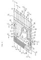
- Fig. 3 being a cross sectional view taken on line A-A of Fig. 2, shows interiors of the stationary blade and the inner shroud.
- the second stage stationary blade 17 consists of a blade portion 25, an outer shroud 27 and the inner shroud 126.
- the rib 40 In the blade portion 25, there are provided the rib 40, and the leading edge passage 42 and the trailing edge passage 44 mutually separated by the rib 40.
- a cylindrical member 46 is provided in the leading edge passage 42 and a cylindrical member 47 is provided in the trailing edge passage 44, and a multiplicity of cooling holes 70, 71 are provided in side walls of the cylindrical members 46, 47, respectively.
- cooling air holes 72, 73 are provided in bottom walls of the cylindrical members 46, 47, respectively.
- the front flange 81 and the rear flange 82 are provided so as to form therebetween the cavity 45.
- the impingement plate 83 is provided so as to form a chamber 78 and also a bottom plate 150 is provided so as to close a bottom portion of the leading edge passage 42 to thereby form an opening portion 68.
- the multiplicity of passages 92 connecting to the cavity 45.
- the opening portion 68 connects to the passage 90' of the front flange 81 so that entire amount of the cooling air from the leading edge passage 42 may flow into the passage 188.
- an adjusting plate 151 is provided so as to make narrower a cross sectional area of flow passage of the passage 188 and to increase flow velocity of the cooling air.
- the turbulators 200 as mentioned above.
- Cooling air 19' enters the cylindrical members 46, 47 and flows through the cooling air holes 70, 71 to impinge on wall surfaces of the leading edge and trailing edge passages 42, 44 for cooling of the wall surfaces with an increased heat transfer effect.
- the cooling air which has cooled the wall surface of the leading edge passage 42 flows to the opening portion 68 to join with the cooling air which has flown through the cooling air hole 72 of the bottom portion of the cylindrical member 46.
- the cooling air which has entered the cylindrical member 47 flows portionally into the cavity 45 through the cooling air hole 73 and portionally flows through the cooling air holes 71 for cooling of the wall surface of the trailing edge passage 44.
- the cooling air which has cooled the wall surface of the trailing edge passage 44 flows portionally through a trailing edge portion 29 of the blade portion 25 to be discharged outside therefrom and portionally flows into the cavity 45 to join with the cooling air which has entered there through the cooling air hole 73 and then enters the chamber 78 or chambers (not shown) through the impingement plates 83, 84 for cooling of a central portion of the inner shroud 126 and is discharged outside through the multiplicity of passages 92 of the trailing edge portion 43.
- the cooling air in the cavity 45 flows out portionally through a hole 67 of a seal supporting portion 66 as shown by air 85 and 86.
- the air 85 flows into a space between the inner shroud 126 and a front stage moving blade thereof, thereby said space is maintained at a higher pressure tan in a passage through which an outside high temperature combustion gas 30 passes so that the high temperature gas is prevented from coming thereinto.
- the air 86 flows through a seal 33 to enter a space between the inner shroud 126 and a rear stage moving blade thereof, thereby this space is maintained likewise at a higher pressure and the high temperature gas is prevented from coming thereinto.
- the cooling air which has been supplied through the leading edge passage 42 for cooling of the blade portion 25 enters the opening portion 68 and entire amount of this air flows into the passage 188 through the passage 90' because of the bottom plate 150.
- the cross sectional area thereof is adjusted by the adjusting plate 151 so as to become narrower and to increase the flow velocity of the air therein. Further, the air flow is agitated by the turbulators 200 and thereby the cooling effect is increased.
- both the leading edge portion 41 and the trailing edge portion 43 are cooled efficiently.
- Fig. 4 being a cross sectional view taken on line B-B of Fig. 2, between the front flange 81 and the rear flange 82 of the inner shroud 126, there are provided the impingement plate 84 having the multiplicity of small holes 101 and the bottom plate 150 for closing the bottom portion of the leading edge passage 42.
- the passage 90' provided in the front flange 81 and a recess portion 100 connect to each other and the entire amount of the cooling air flown from the leading edge passage 42 flows into the passage 188 of the leading edge portion 41 through the passage 90'.
- the adjusting plate 151 and the turbulators 200 are provided, as mentioned before.
- the cooling air flown from the trailing edge passage 44 is injected through the small holes 101 of the impingement plate 84 into the chamber 78 formed by the impingement plate 84 and a recess portion 99, thus all these portions are cooled with enhanced cooling effect.
- Fig. 5 being an enlarged cross sectional view taken on line C-C of Fig. 2, the adjusting plate 151 is provided in the passage 188, thereby the flow passage cross sectional area is made narrower than the prior art case and the flow velocity of the air there is increased. Also, the turbulators 200 are provided to upper and lower wall surfaces of the passage 188, thereby the heat transfer effect by convection is increased.
- the passage 91 of the cooling air which has been provided in the front flange 81 of the leading edge portion 41 in the prior art case is eliminated and the entire amount of the cooling air in the passage 188 of the leading edge portion 41 is caused to flow through the passages 93, 94 provided in the rails 96, 97 of the side edge portions.
- the bottom plate 150 is provided so as to close the bottom portion of the leading edge passage 42.
- the adjusting plate 151 is provided in order to increase the flow velocity of the air in the passage 188 of the leading edge portion 41.
- the turbulators 200 are provided for increasing the cooling effect.
- the entire amount of the cooling air from the leading edge passage 42 flows into the passage 188 of the leading edge portion 41 and this air is used in its entire amount for cooling of the leading edge portion 41 without a portion thereof being taken for cooling of the central portion as has been done in the prior art case, hence the cooling effect of the leading edge portion 41, which is exposed to a high temperature gas and is in a severe temperature condition, is enhanced greatly as compared with the prior art one.
- the adjusting plate 151 is provided in the passage 188 of the leading edge portion 41 so that the flow passage cross sectional area is made narrower and the flow velocity is increased, as compared with the prior art case, and further the turbulators 200 are provided in the passage 188, hence the cooling effect of the passage 188 is enhanced greatly as compared with the prior art case where only the needle-like fins are provided in the passage 88.
- the entire amount of the cooling air which has entered the passage 188 of the leading edge portion 41 further flows separatedly into the passages 93, 94, respectively, of the rails 96, 97 of the side edge portions so that the air amount flowing in the passages 93, 94 increases as compared with the prior art case, hence the cooling effect of the side edge portions which are exposed to the high temperature gas increases.
- the air which has entered the passage 88 portion ally flows into the passage 91 of the front flange 81 for cooling of the central portion and portionally flows into the passages 93, 94.
- the passage 91 is eliminated, hence the amount of the cooling air flowing in the passages 93, 94 increases by that degree.
Landscapes
- Engineering & Computer Science (AREA)
- Mechanical Engineering (AREA)
- General Engineering & Computer Science (AREA)
- Physics & Mathematics (AREA)
- Fluid Mechanics (AREA)
- Turbine Rotor Nozzle Sealing (AREA)
Applications Claiming Priority (3)
| Application Number | Priority Date | Filing Date | Title |
|---|---|---|---|
| JP29540897 | 1997-10-28 | ||
| JP29540897A JP3495579B2 (ja) | 1997-10-28 | 1997-10-28 | ガスタービン静翼 |
| JP295408/97 | 1997-10-28 |
Publications (3)
| Publication Number | Publication Date |
|---|---|
| EP0911486A2 true EP0911486A2 (de) | 1999-04-28 |
| EP0911486A3 EP0911486A3 (de) | 2000-01-05 |
| EP0911486B1 EP0911486B1 (de) | 2004-01-07 |
Family
ID=17820227
Family Applications (1)
| Application Number | Title | Priority Date | Filing Date |
|---|---|---|---|
| EP98120025A Expired - Lifetime EP0911486B1 (de) | 1997-10-28 | 1998-10-22 | Kühlung einer Gasturbinenleitschaufel |
Country Status (5)
| Country | Link |
|---|---|
| US (1) | US6089822A (de) |
| EP (1) | EP0911486B1 (de) |
| JP (1) | JP3495579B2 (de) |
| CA (1) | CA2251198C (de) |
| DE (1) | DE69820958T2 (de) |
Cited By (12)
| Publication number | Priority date | Publication date | Assignee | Title |
|---|---|---|---|---|
| EP1138878A2 (de) | 2000-03-31 | 2001-10-04 | ALSTOM Power N.V. | Plattenförmiger, auskragender Bauteilabschnitt einer Gasturbine |
| EP1275819A2 (de) * | 2001-07-11 | 2003-01-15 | Mitsubishi Heavy Industries, Ltd. | Gasturbinenleitschaufel |
| EP1283326A1 (de) * | 2001-08-09 | 2003-02-12 | Siemens Aktiengesellschaft | Kühlung einer Turbinenschaufel |
| EP1288442A1 (de) * | 2001-08-27 | 2003-03-05 | General Electric Company | Verfahren und Vorrichtung zur Steuerung der Kühlungsströmung in eine Turbinenschaufel |
| EP1384855A2 (de) * | 2002-07-25 | 2004-01-28 | Mitsubishi Heavy Industries, Ltd. | Kühlstruktur einer Turbinenleitschaufel und Gasturbine |
| EP1413714A2 (de) * | 2002-10-22 | 2004-04-28 | Siemens Aktiengesellschaft | Leitschaufel für eine Turbine |
| EP1452693A3 (de) * | 2003-02-27 | 2007-02-21 | General Electric Company | Turbinenleitschaufelträger |
| EP2613012A1 (de) * | 2012-01-09 | 2013-07-10 | General Electric Company | Kühlungsanordnung eines Turbinenleitapparats |
| EP2626519A1 (de) * | 2012-02-09 | 2013-08-14 | Siemens Aktiengesellschaft | Turbinenbaugruppe, zugehöriges Prallkühlungsrohr und Gasturbinenkraftwerk. |
| EP2990607A1 (de) * | 2014-08-28 | 2016-03-02 | Siemens Aktiengesellschaft | Kühlkonzept für Gasturbinenschaufeln |
| EP3009605A4 (de) * | 2014-08-04 | 2016-08-31 | Mitsubishi Hitachi Power Sys | Hochtemperaturbauteil einer gasturbine, gasturbine damit und verfahren zur herstellung eines hochtemperaturbauteils einer gasturbine |
| RU192446U1 (ru) * | 2019-03-13 | 2019-09-17 | Федеральное государственное бюджетное образовательное учреждение высшего образования "Рыбинский государственный авиационный технический университет имени П.А. Соловьева" | Блок сопловых турбинных лопаток с охлаждаемой несимметричной торцевой полкой |
Families Citing this family (37)
| Publication number | Priority date | Publication date | Assignee | Title |
|---|---|---|---|---|
| JP3782637B2 (ja) * | 2000-03-08 | 2006-06-07 | 三菱重工業株式会社 | ガスタービン冷却静翼 |
| US6481959B1 (en) | 2001-04-26 | 2002-11-19 | Honeywell International, Inc. | Gas turbine disk cavity ingestion inhibitor |
| US6508620B2 (en) | 2001-05-17 | 2003-01-21 | Pratt & Whitney Canada Corp. | Inner platform impingement cooling by supply air from outside |
| US6416275B1 (en) * | 2001-05-30 | 2002-07-09 | Gary Michael Itzel | Recessed impingement insert metering plate for gas turbine nozzles |
| FR2851286B1 (fr) * | 2003-02-18 | 2006-07-28 | Snecma Moteurs | Aubes de turbine refroidie a fuite d'air de refroidissement reduite |
| US7008185B2 (en) * | 2003-02-27 | 2006-03-07 | General Electric Company | Gas turbine engine turbine nozzle bifurcated impingement baffle |
| US7118326B2 (en) * | 2004-06-17 | 2006-10-10 | Siemens Power Generation, Inc. | Cooled gas turbine vane |
| US7198468B2 (en) * | 2004-07-15 | 2007-04-03 | Pratt & Whitney Canada Corp. | Internally cooled turbine blade |
| US7464554B2 (en) * | 2004-09-09 | 2008-12-16 | United Technologies Corporation | Gas turbine combustor heat shield panel or exhaust panel including a cooling device |
| US7534088B1 (en) | 2006-06-19 | 2009-05-19 | United Technologies Corporation | Fluid injection system |
| US7611324B2 (en) * | 2006-11-30 | 2009-11-03 | General Electric Company | Method and system to facilitate enhanced local cooling of turbine engines |
| US7921654B1 (en) | 2007-09-07 | 2011-04-12 | Florida Turbine Technologies, Inc. | Cooled turbine stator vane |
| JP2009221995A (ja) * | 2008-03-18 | 2009-10-01 | Ihi Corp | 高温部品の内面冷却構造 |
| JP5180653B2 (ja) * | 2008-03-31 | 2013-04-10 | 三菱重工業株式会社 | ガスタービン翼およびこれを備えたガスタービン |
| JP5078766B2 (ja) * | 2008-06-13 | 2012-11-21 | 三菱重工業株式会社 | タービン静翼構造 |
| US8840369B2 (en) * | 2010-09-30 | 2014-09-23 | General Electric Company | Apparatus and methods for cooling platform regions of turbine rotor blades |
| US8814518B2 (en) * | 2010-10-29 | 2014-08-26 | General Electric Company | Apparatus and methods for cooling platform regions of turbine rotor blades |
| RU2547351C2 (ru) * | 2010-11-29 | 2015-04-10 | Альстом Текнолоджи Лтд | Осевая газовая турбина |
| US8628294B1 (en) * | 2011-05-19 | 2014-01-14 | Florida Turbine Technologies, Inc. | Turbine stator vane with purge air channel |
| US8845289B2 (en) | 2011-11-04 | 2014-09-30 | General Electric Company | Bucket assembly for turbine system |
| US8840370B2 (en) | 2011-11-04 | 2014-09-23 | General Electric Company | Bucket assembly for turbine system |
| US8870525B2 (en) | 2011-11-04 | 2014-10-28 | General Electric Company | Bucket assembly for turbine system |
| US20130170960A1 (en) * | 2012-01-04 | 2013-07-04 | General Electric Company | Turbine assembly and method for reducing fluid flow between turbine components |
| US9011078B2 (en) * | 2012-01-09 | 2015-04-21 | General Electric Company | Turbine vane seal carrier with slots for cooling and assembly |
| US9175565B2 (en) | 2012-08-03 | 2015-11-03 | General Electric Company | Systems and apparatus relating to seals for turbine engines |
| US9194237B2 (en) | 2012-09-10 | 2015-11-24 | General Electric Company | Serpentine cooling of nozzle endwall |
| JP5627718B2 (ja) * | 2013-01-11 | 2014-11-19 | 三菱重工業株式会社 | ガスタービン翼およびこれを備えたガスタービン |
| JP5575279B2 (ja) * | 2013-01-11 | 2014-08-20 | 三菱重工業株式会社 | ガスタービン翼およびこれを備えたガスタービン |
| US10100737B2 (en) | 2013-05-16 | 2018-10-16 | Siemens Energy, Inc. | Impingement cooling arrangement having a snap-in plate |
| WO2016002602A1 (ja) | 2014-06-30 | 2016-01-07 | 三菱日立パワーシステムズ株式会社 | タービン静翼、タービン、及び、タービン静翼の改造方法 |
| GB2559739A (en) * | 2017-02-15 | 2018-08-22 | Rolls Royce Plc | Stator vane section |
| US10677084B2 (en) | 2017-06-16 | 2020-06-09 | Honeywell International Inc. | Turbine tip shroud assembly with plural shroud segments having inter-segment seal arrangement |
| US10900378B2 (en) | 2017-06-16 | 2021-01-26 | Honeywell International Inc. | Turbine tip shroud assembly with plural shroud segments having internal cooling passages |
| US10989067B2 (en) | 2018-07-13 | 2021-04-27 | Honeywell International Inc. | Turbine vane with dust tolerant cooling system |
| KR102224983B1 (ko) * | 2019-10-17 | 2021-03-08 | 한국서부발전 주식회사 | 가스터빈 연소기의 점검 진단 장치 |
| JP2022061204A (ja) * | 2020-10-06 | 2022-04-18 | 三菱重工業株式会社 | ガスタービン静翼 |
| US11536149B1 (en) * | 2022-03-11 | 2022-12-27 | Mitsubishi Heavy Industries, Ltd. | Cooling method and structure of vane of gas turbine |
Citations (4)
| Publication number | Priority date | Publication date | Assignee | Title |
|---|---|---|---|---|
| GB2093923A (en) * | 1981-03-02 | 1982-09-08 | Westinghouse Electric Corp | Air cooled gas turbine vane structure |
| JPH05163959A (ja) * | 1991-12-16 | 1993-06-29 | Tohoku Electric Power Co Inc | タービン静翼 |
| US5609466A (en) * | 1994-11-10 | 1997-03-11 | Westinghouse Electric Corporation | Gas turbine vane with a cooled inner shroud |
| US5634766A (en) * | 1994-08-23 | 1997-06-03 | General Electric Co. | Turbine stator vane segments having combined air and steam cooling circuits |
Family Cites Families (1)
| Publication number | Priority date | Publication date | Assignee | Title |
|---|---|---|---|---|
| US5320483A (en) * | 1992-12-30 | 1994-06-14 | General Electric Company | Steam and air cooling for stator stage of a turbine |
-
1997
- 1997-10-28 JP JP29540897A patent/JP3495579B2/ja not_active Expired - Lifetime
-
1998
- 1998-10-20 CA CA002251198A patent/CA2251198C/en not_active Expired - Lifetime
- 1998-10-22 DE DE69820958T patent/DE69820958T2/de not_active Expired - Lifetime
- 1998-10-22 EP EP98120025A patent/EP0911486B1/de not_active Expired - Lifetime
- 1998-10-28 US US09/179,816 patent/US6089822A/en not_active Expired - Lifetime
Patent Citations (4)
| Publication number | Priority date | Publication date | Assignee | Title |
|---|---|---|---|---|
| GB2093923A (en) * | 1981-03-02 | 1982-09-08 | Westinghouse Electric Corp | Air cooled gas turbine vane structure |
| JPH05163959A (ja) * | 1991-12-16 | 1993-06-29 | Tohoku Electric Power Co Inc | タービン静翼 |
| US5634766A (en) * | 1994-08-23 | 1997-06-03 | General Electric Co. | Turbine stator vane segments having combined air and steam cooling circuits |
| US5609466A (en) * | 1994-11-10 | 1997-03-11 | Westinghouse Electric Corporation | Gas turbine vane with a cooled inner shroud |
Non-Patent Citations (1)
| Title |
|---|
| PATENT ABSTRACTS OF JAPAN vol. 017, no. 572 (M-1497), 18 October 1993 (1993-10-18) -& JP 05 163959 A (TOHOKU ELECTRIC POWER CO INC;OTHERS: 01), 29 June 1993 (1993-06-29) * |
Cited By (24)
| Publication number | Priority date | Publication date | Assignee | Title |
|---|---|---|---|---|
| EP1138878A2 (de) | 2000-03-31 | 2001-10-04 | ALSTOM Power N.V. | Plattenförmiger, auskragender Bauteilabschnitt einer Gasturbine |
| EP1275819A2 (de) * | 2001-07-11 | 2003-01-15 | Mitsubishi Heavy Industries, Ltd. | Gasturbinenleitschaufel |
| EP1275819A3 (de) * | 2001-07-11 | 2009-06-17 | Mitsubishi Heavy Industries, Ltd. | Gasturbinenleitschaufel |
| EP1283326A1 (de) * | 2001-08-09 | 2003-02-12 | Siemens Aktiengesellschaft | Kühlung einer Turbinenschaufel |
| US6905301B2 (en) | 2001-08-09 | 2005-06-14 | Siemens Aktiengesellschaft | Turbine blade/vane |
| EP1288442A1 (de) * | 2001-08-27 | 2003-03-05 | General Electric Company | Verfahren und Vorrichtung zur Steuerung der Kühlungsströmung in eine Turbinenschaufel |
| EP1384855A3 (de) * | 2002-07-25 | 2005-08-17 | Mitsubishi Heavy Industries, Ltd. | Kühlstruktur einer Turbinenleitschaufel und Gasturbine |
| EP1384855A2 (de) * | 2002-07-25 | 2004-01-28 | Mitsubishi Heavy Industries, Ltd. | Kühlstruktur einer Turbinenleitschaufel und Gasturbine |
| EP1413714A3 (de) * | 2002-10-22 | 2004-12-22 | Siemens Aktiengesellschaft | Leitschaufel für eine Turbine |
| EP1413714A2 (de) * | 2002-10-22 | 2004-04-28 | Siemens Aktiengesellschaft | Leitschaufel für eine Turbine |
| EP1452693A3 (de) * | 2003-02-27 | 2007-02-21 | General Electric Company | Turbinenleitschaufelträger |
| US8944751B2 (en) | 2012-01-09 | 2015-02-03 | General Electric Company | Turbine nozzle cooling assembly |
| EP2613012A1 (de) * | 2012-01-09 | 2013-07-10 | General Electric Company | Kühlungsanordnung eines Turbinenleitapparats |
| EP2626519A1 (de) * | 2012-02-09 | 2013-08-14 | Siemens Aktiengesellschaft | Turbinenbaugruppe, zugehöriges Prallkühlungsrohr und Gasturbinenkraftwerk. |
| US10012093B2 (en) | 2012-02-09 | 2018-07-03 | Siemens Aktiengesellschaft | Impingement cooling of turbine blades or vanes |
| EP3009605A4 (de) * | 2014-08-04 | 2016-08-31 | Mitsubishi Hitachi Power Sys | Hochtemperaturbauteil einer gasturbine, gasturbine damit und verfahren zur herstellung eines hochtemperaturbauteils einer gasturbine |
| US9540934B2 (en) | 2014-08-04 | 2017-01-10 | Mitsubishi Hitachi Power Systems, Ltd. | Hot part of gas turbine, gas turbine including the same, and manufacturing method of hot part of gas turbine |
| EP2990607A1 (de) * | 2014-08-28 | 2016-03-02 | Siemens Aktiengesellschaft | Kühlkonzept für Gasturbinenschaufeln |
| WO2016030157A1 (en) * | 2014-08-28 | 2016-03-03 | Siemens Aktiengesellschaft | Cooling concept for turbine blades or vanes |
| CN106795772A (zh) * | 2014-08-28 | 2017-05-31 | 西门子股份公司 | 用于涡轮叶片或导叶的冷却概念 |
| RU2671251C2 (ru) * | 2014-08-28 | 2018-10-30 | Сименс Акциенгезелльшафт | Принцип охлаждения для лопаток или направляющих лопаток турбины |
| CN106795772B (zh) * | 2014-08-28 | 2018-11-13 | 西门子股份公司 | 用于涡轮叶片或导叶的冷却概念 |
| US10513933B2 (en) | 2014-08-28 | 2019-12-24 | Siemens Aktiengesellschaft | Cooling concept for turbine blades or vanes |
| RU192446U1 (ru) * | 2019-03-13 | 2019-09-17 | Федеральное государственное бюджетное образовательное учреждение высшего образования "Рыбинский государственный авиационный технический университет имени П.А. Соловьева" | Блок сопловых турбинных лопаток с охлаждаемой несимметричной торцевой полкой |
Also Published As
| Publication number | Publication date |
|---|---|
| CA2251198C (en) | 2002-01-01 |
| EP0911486A3 (de) | 2000-01-05 |
| DE69820958T2 (de) | 2004-10-21 |
| CA2251198A1 (en) | 1999-04-28 |
| JPH11132005A (ja) | 1999-05-18 |
| JP3495579B2 (ja) | 2004-02-09 |
| US6089822A (en) | 2000-07-18 |
| DE69820958D1 (de) | 2004-02-12 |
| EP0911486B1 (de) | 2004-01-07 |
Similar Documents
| Publication | Publication Date | Title |
|---|---|---|
| EP0911486B1 (de) | Kühlung einer Gasturbinenleitschaufel | |
| JP3978143B2 (ja) | 静翼の冷却構造及びガスタービン | |
| US6481966B2 (en) | Blade for gas turbines with choke cross section at the trailing edge | |
| US6422817B1 (en) | Cooling circuit for and method of cooling a gas turbine bucket | |
| US6428273B1 (en) | Truncated rib turbine nozzle | |
| JP6030826B2 (ja) | タービンロータブレードのプラットフォーム領域を冷却するための装置および方法 | |
| US9011077B2 (en) | Cooled airfoil in a turbine engine | |
| US6561757B2 (en) | Turbine vane segment and impingement insert configuration for fail-safe impingement insert retention | |
| US6506013B1 (en) | Film cooling for a closed loop cooled airfoil | |
| US6435814B1 (en) | Film cooling air pocket in a closed loop cooled airfoil | |
| EP1143107A2 (de) | Kühlung des Endrahmens eines Turbineneinlasskanals | |
| JP2004257389A (ja) | タービンノズルセグメントの片持ち式支持 | |
| JP2004257392A (ja) | 二分割空洞を有する単一の中空ベーンを備えたガスタービンエンジンのタービンノズルセグメント | |
| KR100671573B1 (ko) | 가스 터빈 노즐 및 국부적인 영역 냉각 방법 | |
| JP2004257390A (ja) | ガスタービンエンジンのタービンノズルの二又状インピンジメントバッフル | |
| US6406254B1 (en) | Cooling circuit for steam and air-cooled turbine nozzle stage | |
| US6468031B1 (en) | Nozzle cavity impingement/area reduction insert | |
| US6416275B1 (en) | Recessed impingement insert metering plate for gas turbine nozzles | |
| IL35196A (en) | Fluid cooled vane assembly | |
| JPS623298B2 (de) | ||
| US6390769B1 (en) | Closed circuit steam cooled turbine shroud and method for steam cooling turbine shroud | |
| WO2023171745A1 (ja) | ガスタービンの静翼の冷却方法および冷却構造 | |
| JP2005061412A (ja) | 冷却式ガスタービンエンジン羽根 | |
| US5062262A (en) | Cooling of turbine nozzles | |
| JP3368417B2 (ja) | タービン静翼 |
Legal Events
| Date | Code | Title | Description |
|---|---|---|---|
| PUAI | Public reference made under article 153(3) epc to a published international application that has entered the european phase |
Free format text: ORIGINAL CODE: 0009012 |
|
| 17P | Request for examination filed |
Effective date: 19981119 |
|
| AK | Designated contracting states |
Kind code of ref document: A2 Designated state(s): CH DE FR GB IT LI |
|
| AX | Request for extension of the european patent |
Free format text: AL;LT;LV;MK;RO;SI |
|
| PUAL | Search report despatched |
Free format text: ORIGINAL CODE: 0009013 |
|
| AK | Designated contracting states |
Kind code of ref document: A3 Designated state(s): AT BE CH CY DE DK ES FI FR GB GR IE IT LI LU MC NL PT SE |
|
| AX | Request for extension of the european patent |
Free format text: AL;LT;LV;MK;RO;SI |
|
| RIC1 | Information provided on ipc code assigned before grant |
Free format text: 7F 01D 9/04 A, 7F 01D 25/12 B, 7F 01D 5/18 B |
|
| AKX | Designation fees paid |
Free format text: CH DE FR GB IT LI |
|
| 17Q | First examination report despatched |
Effective date: 20020326 |
|
| GRAH | Despatch of communication of intention to grant a patent |
Free format text: ORIGINAL CODE: EPIDOS IGRA |
|
| GRAH | Despatch of communication of intention to grant a patent |
Free format text: ORIGINAL CODE: EPIDOS IGRA |
|
| GRAA | (expected) grant |
Free format text: ORIGINAL CODE: 0009210 |
|
| AK | Designated contracting states |
Kind code of ref document: B1 Designated state(s): CH DE FR GB IT LI |
|
| REG | Reference to a national code |
Ref country code: GB Ref legal event code: FG4D |
|
| REG | Reference to a national code |
Ref country code: CH Ref legal event code: EP |
|
| REF | Corresponds to: |
Ref document number: 69820958 Country of ref document: DE Date of ref document: 20040212 Kind code of ref document: P |
|
| REG | Reference to a national code |
Ref country code: CH Ref legal event code: NV Representative=s name: E. BLUM & CO. PATENTANWAELTE |
|
| ET | Fr: translation filed | ||
| PLBE | No opposition filed within time limit |
Free format text: ORIGINAL CODE: 0009261 |
|
| STAA | Information on the status of an ep patent application or granted ep patent |
Free format text: STATUS: NO OPPOSITION FILED WITHIN TIME LIMIT |
|
| 26N | No opposition filed |
Effective date: 20041008 |
|
| REG | Reference to a national code |
Ref country code: CH Ref legal event code: PFA Owner name: MITSUBISHI HEAVY INDUSTRIES, LTD. Free format text: MITSUBISHI HEAVY INDUSTRIES, LTD.#5-1, MARUNOUCHI 2-CHOME, CHIYODA-KU,#TOKYO 100-0005 (JP) -TRANSFER TO- MITSUBISHI HEAVY INDUSTRIES, LTD.#5-1, MARUNOUCHI 2-CHOME, CHIYODA-KU,#TOKYO 100-0005 (JP) |
|
| REG | Reference to a national code |
Ref country code: DE Ref legal event code: R082 Ref document number: 69820958 Country of ref document: DE Representative=s name: PATENTANWAELTE HENKEL, BREUER & PARTNER, DE Ref country code: DE Ref legal event code: R081 Ref document number: 69820958 Country of ref document: DE Owner name: MITSUBISHI HITACHI POWER SYSTEMS, LTD., YOKOHA, JP Free format text: FORMER OWNER: MITSUBISHI HEAVY INDUSTRIES, LTD., TOKYO, JP |
|
| REG | Reference to a national code |
Ref country code: FR Ref legal event code: PLFP Year of fee payment: 18 |
|
| REG | Reference to a national code |
Ref country code: FR Ref legal event code: CA Effective date: 20151119 |
|
| REG | Reference to a national code |
Ref country code: GB Ref legal event code: 732E Free format text: REGISTERED BETWEEN 20151203 AND 20151209 |
|
| REG | Reference to a national code |
Ref country code: FR Ref legal event code: TP Owner name: MITSUBISHI HITACHI POWER SYSTEMS, LTD., JP Effective date: 20151222 |
|
| REG | Reference to a national code |
Ref country code: FR Ref legal event code: PLFP Year of fee payment: 19 |
|
| REG | Reference to a national code |
Ref country code: CH Ref legal event code: PCOW Free format text: NEW ADDRESS: 16-5, KONAN 2-CHOME MINATO-KU, TOKYO 108-8215 (JP) |
|
| REG | Reference to a national code |
Ref country code: CH Ref legal event code: PUE Owner name: MITSUBISHI HITACHI POWER SYSTEMS, LTD., JP Free format text: FORMER OWNER: MITSUBISHI HEAVY INDUSTRIES, LTD., JP Ref country code: CH Ref legal event code: NV Representative=s name: SCHNEIDER FELDMANN AG PATENT- UND MARKENANWAEL, CH |
|
| REG | Reference to a national code |
Ref country code: FR Ref legal event code: PLFP Year of fee payment: 20 |
|
| PGFP | Annual fee paid to national office [announced via postgrant information from national office to epo] |
Ref country code: FR Payment date: 20170918 Year of fee payment: 20 |
|
| PGFP | Annual fee paid to national office [announced via postgrant information from national office to epo] |
Ref country code: DE Payment date: 20171018 Year of fee payment: 20 |
|
| PGFP | Annual fee paid to national office [announced via postgrant information from national office to epo] |
Ref country code: CH Payment date: 20171013 Year of fee payment: 20 Ref country code: GB Payment date: 20171018 Year of fee payment: 20 Ref country code: IT Payment date: 20171024 Year of fee payment: 20 |
|
| REG | Reference to a national code |
Ref country code: DE Ref legal event code: R071 Ref document number: 69820958 Country of ref document: DE |
|
| REG | Reference to a national code |
Ref country code: CH Ref legal event code: PL |
|
| REG | Reference to a national code |
Ref country code: GB Ref legal event code: PE20 Expiry date: 20181021 |
|
| PG25 | Lapsed in a contracting state [announced via postgrant information from national office to epo] |
Ref country code: GB Free format text: LAPSE BECAUSE OF EXPIRATION OF PROTECTION Effective date: 20181021 |