EP1138481A2 - Lithographic printing machine and lithographic printing method - Google Patents
Lithographic printing machine and lithographic printing method Download PDFInfo
- Publication number
- EP1138481A2 EP1138481A2 EP01107730A EP01107730A EP1138481A2 EP 1138481 A2 EP1138481 A2 EP 1138481A2 EP 01107730 A EP01107730 A EP 01107730A EP 01107730 A EP01107730 A EP 01107730A EP 1138481 A2 EP1138481 A2 EP 1138481A2
- Authority
- EP
- European Patent Office
- Prior art keywords
- group
- imaging
- lithographic printing
- plate cylinder
- unit
- Prior art date
- Legal status (The legal status is an assumption and is not a legal conclusion. Google has not performed a legal analysis and makes no representation as to the accuracy of the status listed.)
- Withdrawn
Links
- 238000007639 printing Methods 0.000 title claims abstract description 121
- 238000000034 method Methods 0.000 title claims abstract description 44
- 238000003384 imaging method Methods 0.000 claims abstract description 84
- 125000000524 functional group Chemical group 0.000 claims abstract description 70
- 229920000642 polymer Polymers 0.000 claims abstract description 55
- 238000000576 coating method Methods 0.000 claims abstract description 31
- 239000011248 coating agent Substances 0.000 claims abstract description 29
- 230000002209 hydrophobic effect Effects 0.000 claims abstract description 25
- 238000004140 cleaning Methods 0.000 claims abstract description 22
- 239000007888 film coating Substances 0.000 claims abstract description 7
- 238000009501 film coating Methods 0.000 claims abstract description 7
- 230000005855 radiation Effects 0.000 claims description 50
- 238000006243 chemical reaction Methods 0.000 claims description 34
- 239000007787 solid Substances 0.000 claims description 17
- 238000010438 heat treatment Methods 0.000 claims description 16
- 150000007942 carboxylates Chemical group 0.000 claims description 7
- 125000002843 carboxylic acid group Chemical group 0.000 claims description 6
- 150000001768 cations Chemical class 0.000 claims description 6
- 125000000542 sulfonic acid group Chemical group 0.000 claims description 5
- 229910052783 alkali metal Inorganic materials 0.000 claims description 3
- 150000001340 alkali metals Chemical class 0.000 claims description 3
- 229910052784 alkaline earth metal Inorganic materials 0.000 claims description 3
- 150000001342 alkaline earth metals Chemical class 0.000 claims description 3
- 230000000737 periodic effect Effects 0.000 claims description 3
- ABLZXFCXXLZCGV-UHFFFAOYSA-N phosphonic acid group Chemical group P(O)(O)=O ABLZXFCXXLZCGV-UHFFFAOYSA-N 0.000 claims description 3
- -1 carbamoyloxy group Chemical group 0.000 description 120
- 239000002245 particle Substances 0.000 description 70
- 239000010410 layer Substances 0.000 description 69
- 150000001875 compounds Chemical class 0.000 description 64
- 239000000049 pigment Substances 0.000 description 41
- 239000000178 monomer Substances 0.000 description 36
- 125000000217 alkyl group Chemical group 0.000 description 33
- 238000004132 cross linking Methods 0.000 description 31
- 125000003118 aryl group Chemical group 0.000 description 29
- 239000000975 dye Substances 0.000 description 29
- 239000000843 powder Substances 0.000 description 26
- 239000000463 material Substances 0.000 description 25
- XEEYBQQBJWHFJM-UHFFFAOYSA-N Iron Chemical compound [Fe] XEEYBQQBJWHFJM-UHFFFAOYSA-N 0.000 description 23
- XLYOFNOQVPJJNP-UHFFFAOYSA-N water Substances O XLYOFNOQVPJJNP-UHFFFAOYSA-N 0.000 description 21
- 125000004432 carbon atom Chemical group C* 0.000 description 18
- 229910052751 metal Inorganic materials 0.000 description 18
- 239000002184 metal Substances 0.000 description 18
- 229920005989 resin Polymers 0.000 description 18
- 239000011347 resin Substances 0.000 description 18
- 239000002585 base Substances 0.000 description 16
- 239000002243 precursor Substances 0.000 description 16
- RTAQQCXQSZGOHL-UHFFFAOYSA-N Titanium Chemical compound [Ti] RTAQQCXQSZGOHL-UHFFFAOYSA-N 0.000 description 15
- 229910052709 silver Inorganic materials 0.000 description 14
- 229910052782 aluminium Inorganic materials 0.000 description 13
- 239000000976 ink Substances 0.000 description 13
- 239000010954 inorganic particle Substances 0.000 description 13
- 125000000325 methylidene group Chemical group [H]C([H])=* 0.000 description 13
- 125000001424 substituent group Chemical group 0.000 description 12
- 229910052742 iron Inorganic materials 0.000 description 11
- 239000000126 substance Substances 0.000 description 11
- FBPFZTCFMRRESA-FSIIMWSLSA-N D-Glucitol Natural products OC[C@H](O)[C@H](O)[C@@H](O)[C@H](O)CO FBPFZTCFMRRESA-FSIIMWSLSA-N 0.000 description 10
- FBPFZTCFMRRESA-JGWLITMVSA-N D-glucitol Chemical compound OC[C@H](O)[C@@H](O)[C@H](O)[C@H](O)CO FBPFZTCFMRRESA-JGWLITMVSA-N 0.000 description 10
- PXHVJJICTQNCMI-UHFFFAOYSA-N Nickel Chemical compound [Ni] PXHVJJICTQNCMI-UHFFFAOYSA-N 0.000 description 10
- BQCADISMDOOEFD-UHFFFAOYSA-N Silver Chemical compound [Ag] BQCADISMDOOEFD-UHFFFAOYSA-N 0.000 description 10
- 238000011161 development Methods 0.000 description 10
- 230000007062 hydrolysis Effects 0.000 description 10
- 238000006460 hydrolysis reaction Methods 0.000 description 10
- 239000004332 silver Substances 0.000 description 10
- 239000002904 solvent Substances 0.000 description 10
- 239000000600 sorbitol Substances 0.000 description 10
- 239000010936 titanium Substances 0.000 description 10
- 239000002253 acid Substances 0.000 description 9
- 229920001577 copolymer Polymers 0.000 description 9
- 239000006185 dispersion Substances 0.000 description 9
- 239000010419 fine particle Substances 0.000 description 9
- 125000004435 hydrogen atom Chemical group [H]* 0.000 description 9
- 239000003921 oil Substances 0.000 description 9
- 239000011146 organic particle Substances 0.000 description 9
- 229910052719 titanium Inorganic materials 0.000 description 9
- OKKJLVBELUTLKV-UHFFFAOYSA-N Methanol Chemical class OC OKKJLVBELUTLKV-UHFFFAOYSA-N 0.000 description 8
- MCMNRKCIXSYSNV-UHFFFAOYSA-N Zirconium dioxide Chemical compound O=[Zr]=O MCMNRKCIXSYSNV-UHFFFAOYSA-N 0.000 description 8
- 239000010408 film Substances 0.000 description 8
- 125000005843 halogen group Chemical group 0.000 description 8
- 239000013528 metallic particle Substances 0.000 description 8
- 150000002739 metals Chemical class 0.000 description 8
- 239000000203 mixture Substances 0.000 description 8
- 229910052759 nickel Inorganic materials 0.000 description 8
- 229910052710 silicon Inorganic materials 0.000 description 8
- 238000011282 treatment Methods 0.000 description 8
- 229910052727 yttrium Inorganic materials 0.000 description 8
- 229910000859 α-Fe Inorganic materials 0.000 description 8
- 150000001252 acrylic acid derivatives Chemical class 0.000 description 7
- 125000003545 alkoxy group Chemical group 0.000 description 7
- 125000002887 hydroxy group Chemical group [H]O* 0.000 description 7
- WEVYAHXRMPXWCK-UHFFFAOYSA-N Acetonitrile Chemical compound CC#N WEVYAHXRMPXWCK-UHFFFAOYSA-N 0.000 description 6
- 229920002134 Carboxymethyl cellulose Polymers 0.000 description 6
- LFQSCWFLJHTTHZ-UHFFFAOYSA-N Ethanol Chemical compound CCO LFQSCWFLJHTTHZ-UHFFFAOYSA-N 0.000 description 6
- 239000004793 Polystyrene Substances 0.000 description 6
- VYPSYNLAJGMNEJ-UHFFFAOYSA-N Silicium dioxide Chemical compound O=[Si]=O VYPSYNLAJGMNEJ-UHFFFAOYSA-N 0.000 description 6
- 125000001931 aliphatic group Chemical group 0.000 description 6
- 125000002947 alkylene group Chemical group 0.000 description 6
- 125000004429 atom Chemical group 0.000 description 6
- 235000010948 carboxy methyl cellulose Nutrition 0.000 description 6
- 229910052804 chromium Inorganic materials 0.000 description 6
- 239000011651 chromium Substances 0.000 description 6
- 239000000499 gel Substances 0.000 description 6
- IQPQWNKOIGAROB-UHFFFAOYSA-N isocyanate group Chemical group [N-]=C=O IQPQWNKOIGAROB-UHFFFAOYSA-N 0.000 description 6
- 125000002496 methyl group Chemical group [H]C([H])([H])* 0.000 description 6
- 125000001997 phenyl group Chemical group [H]C1=C([H])C([H])=C(*)C([H])=C1[H] 0.000 description 6
- 125000001476 phosphono group Chemical group [H]OP(*)(=O)O[H] 0.000 description 6
- 229920001169 thermoplastic Polymers 0.000 description 6
- 125000000391 vinyl group Chemical group [H]C([*])=C([H])[H] 0.000 description 6
- 229910052726 zirconium Inorganic materials 0.000 description 6
- QGKMIGUHVLGJBR-UHFFFAOYSA-M (4z)-1-(3-methylbutyl)-4-[[1-(3-methylbutyl)quinolin-1-ium-4-yl]methylidene]quinoline;iodide Chemical compound [I-].C12=CC=CC=C2N(CCC(C)C)C=CC1=CC1=CC=[N+](CCC(C)C)C2=CC=CC=C12 QGKMIGUHVLGJBR-UHFFFAOYSA-M 0.000 description 5
- 150000007513 acids Chemical class 0.000 description 5
- 125000004453 alkoxycarbonyl group Chemical group 0.000 description 5
- 229910052802 copper Inorganic materials 0.000 description 5
- 239000010949 copper Substances 0.000 description 5
- 125000001495 ethyl group Chemical group [H]C([H])([H])C([H])([H])* 0.000 description 5
- 239000003999 initiator Substances 0.000 description 5
- 150000002734 metacrylic acid derivatives Chemical class 0.000 description 5
- 150000004767 nitrides Chemical class 0.000 description 5
- 239000012071 phase Substances 0.000 description 5
- 230000008569 process Effects 0.000 description 5
- 238000001179 sorption measurement Methods 0.000 description 5
- 125000000547 substituted alkyl group Chemical group 0.000 description 5
- SMZOUWXMTYCWNB-UHFFFAOYSA-N 2-(2-methoxy-5-methylphenyl)ethanamine Chemical compound COC1=CC=C(C)C=C1CCN SMZOUWXMTYCWNB-UHFFFAOYSA-N 0.000 description 4
- NIXOWILDQLNWCW-UHFFFAOYSA-N 2-Propenoic acid Natural products OC(=O)C=C NIXOWILDQLNWCW-UHFFFAOYSA-N 0.000 description 4
- 239000004593 Epoxy Substances 0.000 description 4
- 229910000640 Fe alloy Inorganic materials 0.000 description 4
- QIGBRXMKCJKVMJ-UHFFFAOYSA-N Hydroquinone Chemical compound OC1=CC=C(O)C=C1 QIGBRXMKCJKVMJ-UHFFFAOYSA-N 0.000 description 4
- UQSXHKLRYXJYBZ-UHFFFAOYSA-N Iron oxide Chemical compound [Fe]=O UQSXHKLRYXJYBZ-UHFFFAOYSA-N 0.000 description 4
- CERQOIWHTDAKMF-UHFFFAOYSA-N Methacrylic acid Chemical compound CC(=C)C(O)=O CERQOIWHTDAKMF-UHFFFAOYSA-N 0.000 description 4
- 229910052779 Neodymium Inorganic materials 0.000 description 4
- 229910018830 PO3H Inorganic materials 0.000 description 4
- 239000006087 Silane Coupling Agent Substances 0.000 description 4
- PPBRXRYQALVLMV-UHFFFAOYSA-N Styrene Chemical compound C=CC1=CC=CC=C1 PPBRXRYQALVLMV-UHFFFAOYSA-N 0.000 description 4
- 238000010521 absorption reaction Methods 0.000 description 4
- 229940114077 acrylic acid Drugs 0.000 description 4
- 125000002252 acyl group Chemical group 0.000 description 4
- 125000003342 alkenyl group Chemical group 0.000 description 4
- 150000004703 alkoxides Chemical class 0.000 description 4
- 150000004645 aluminates Chemical class 0.000 description 4
- 150000008064 anhydrides Chemical class 0.000 description 4
- 125000004104 aryloxy group Chemical group 0.000 description 4
- 230000005540 biological transmission Effects 0.000 description 4
- 229910052796 boron Inorganic materials 0.000 description 4
- 125000000484 butyl group Chemical group [H]C([*])([H])C([H])([H])C([H])([H])C([H])([H])[H] 0.000 description 4
- 125000003178 carboxy group Chemical group [H]OC(*)=O 0.000 description 4
- 150000001735 carboxylic acids Chemical class 0.000 description 4
- 229910052801 chlorine Inorganic materials 0.000 description 4
- 125000001309 chloro group Chemical group Cl* 0.000 description 4
- 150000002148 esters Chemical class 0.000 description 4
- 125000002485 formyl group Chemical group [H]C(*)=O 0.000 description 4
- 230000006870 function Effects 0.000 description 4
- 229910000765 intermetallic Inorganic materials 0.000 description 4
- 229910052746 lanthanum Inorganic materials 0.000 description 4
- 229910052748 manganese Inorganic materials 0.000 description 4
- 239000011572 manganese Substances 0.000 description 4
- 239000011159 matrix material Substances 0.000 description 4
- 229910044991 metal oxide Inorganic materials 0.000 description 4
- FQPSGWSUVKBHSU-UHFFFAOYSA-N methacrylamide Chemical class CC(=C)C(N)=O FQPSGWSUVKBHSU-UHFFFAOYSA-N 0.000 description 4
- SNVLJLYUUXKWOJ-UHFFFAOYSA-N methylidenecarbene Chemical compound C=[C] SNVLJLYUUXKWOJ-UHFFFAOYSA-N 0.000 description 4
- 229910052750 molybdenum Inorganic materials 0.000 description 4
- 125000000449 nitro group Chemical group [O-][N+](*)=O 0.000 description 4
- 238000007645 offset printing Methods 0.000 description 4
- 239000000047 product Substances 0.000 description 4
- 125000005372 silanol group Chemical group 0.000 description 4
- 238000003860 storage Methods 0.000 description 4
- 239000004094 surface-active agent Substances 0.000 description 4
- 238000003786 synthesis reaction Methods 0.000 description 4
- 229910052718 tin Inorganic materials 0.000 description 4
- 229910052721 tungsten Inorganic materials 0.000 description 4
- 229910052720 vanadium Inorganic materials 0.000 description 4
- 229910052725 zinc Inorganic materials 0.000 description 4
- 239000011701 zinc Substances 0.000 description 4
- ZWEHNKRNPOVVGH-UHFFFAOYSA-N 2-Butanone Chemical compound CCC(C)=O ZWEHNKRNPOVVGH-UHFFFAOYSA-N 0.000 description 3
- TXBCBTDQIULDIA-UHFFFAOYSA-N 2-[[3-hydroxy-2,2-bis(hydroxymethyl)propoxy]methyl]-2-(hydroxymethyl)propane-1,3-diol Chemical compound OCC(CO)(CO)COCC(CO)(CO)CO TXBCBTDQIULDIA-UHFFFAOYSA-N 0.000 description 3
- NIXOWILDQLNWCW-UHFFFAOYSA-M Acrylate Chemical compound [O-]C(=O)C=C NIXOWILDQLNWCW-UHFFFAOYSA-M 0.000 description 3
- WKBOTKDWSSQWDR-UHFFFAOYSA-N Bromine atom Chemical compound [Br] WKBOTKDWSSQWDR-UHFFFAOYSA-N 0.000 description 3
- OKTJSMMVPCPJKN-UHFFFAOYSA-N Carbon Chemical compound [C] OKTJSMMVPCPJKN-UHFFFAOYSA-N 0.000 description 3
- ZAMOUSCENKQFHK-UHFFFAOYSA-N Chlorine atom Chemical compound [Cl] ZAMOUSCENKQFHK-UHFFFAOYSA-N 0.000 description 3
- WSFSSNUMVMOOMR-UHFFFAOYSA-N Formaldehyde Chemical compound O=C WSFSSNUMVMOOMR-UHFFFAOYSA-N 0.000 description 3
- VEXZGXHMUGYJMC-UHFFFAOYSA-N Hydrochloric acid Chemical compound Cl VEXZGXHMUGYJMC-UHFFFAOYSA-N 0.000 description 3
- KFZMGEQAYNKOFK-UHFFFAOYSA-N Isopropanol Chemical compound CC(C)O KFZMGEQAYNKOFK-UHFFFAOYSA-N 0.000 description 3
- VVQNEPGJFQJSBK-UHFFFAOYSA-N Methyl methacrylate Chemical compound COC(=O)C(C)=C VVQNEPGJFQJSBK-UHFFFAOYSA-N 0.000 description 3
- ZMXDDKWLCZADIW-UHFFFAOYSA-N N,N-Dimethylformamide Chemical compound CN(C)C=O ZMXDDKWLCZADIW-UHFFFAOYSA-N 0.000 description 3
- 125000005118 N-alkylcarbamoyl group Chemical group 0.000 description 3
- BOTDANWDWHJENH-UHFFFAOYSA-N Tetraethyl orthosilicate Chemical compound CCO[Si](OCC)(OCC)OCC BOTDANWDWHJENH-UHFFFAOYSA-N 0.000 description 3
- YXFVVABEGXRONW-UHFFFAOYSA-N Toluene Chemical compound CC1=CC=CC=C1 YXFVVABEGXRONW-UHFFFAOYSA-N 0.000 description 3
- 238000002835 absorbance Methods 0.000 description 3
- 239000006096 absorbing agent Substances 0.000 description 3
- 150000003926 acrylamides Chemical class 0.000 description 3
- 229940048053 acrylate Drugs 0.000 description 3
- 125000004442 acylamino group Chemical group 0.000 description 3
- 125000004423 acyloxy group Chemical group 0.000 description 3
- 125000004414 alkyl thio group Chemical group 0.000 description 3
- 125000000304 alkynyl group Chemical group 0.000 description 3
- XAGFODPZIPBFFR-UHFFFAOYSA-N aluminium Chemical compound [Al] XAGFODPZIPBFFR-UHFFFAOYSA-N 0.000 description 3
- 125000004397 aminosulfonyl group Chemical group NS(=O)(=O)* 0.000 description 3
- 229910052787 antimony Inorganic materials 0.000 description 3
- 125000005161 aryl oxy carbonyl group Chemical group 0.000 description 3
- 125000005110 aryl thio group Chemical group 0.000 description 3
- 239000000987 azo dye Substances 0.000 description 3
- 230000015572 biosynthetic process Effects 0.000 description 3
- 125000003917 carbamoyl group Chemical group [H]N([H])C(*)=O 0.000 description 3
- 239000006229 carbon black Substances 0.000 description 3
- 239000007795 chemical reaction product Substances 0.000 description 3
- 239000000460 chlorine Substances 0.000 description 3
- 239000003086 colorant Substances 0.000 description 3
- 229920006037 cross link polymer Polymers 0.000 description 3
- 125000004093 cyano group Chemical group *C#N 0.000 description 3
- 230000000694 effects Effects 0.000 description 3
- 238000007720 emulsion polymerization reaction Methods 0.000 description 3
- 229910052737 gold Inorganic materials 0.000 description 3
- 125000004051 hexyl group Chemical group [H]C([H])([H])C([H])([H])C([H])([H])C([H])([H])C([H])([H])C([H])([H])* 0.000 description 3
- RAXXELZNTBOGNW-UHFFFAOYSA-N imidazole Natural products C1=CNC=N1 RAXXELZNTBOGNW-UHFFFAOYSA-N 0.000 description 3
- 239000002563 ionic surfactant Substances 0.000 description 3
- 239000012948 isocyanate Substances 0.000 description 3
- 229910052745 lead Inorganic materials 0.000 description 3
- 150000001247 metal acetylides Chemical class 0.000 description 3
- 125000001624 naphthyl group Chemical group 0.000 description 3
- 239000002736 nonionic surfactant Substances 0.000 description 3
- 229910052763 palladium Inorganic materials 0.000 description 3
- 125000000394 phosphonato group Chemical group [O-]P([O-])(*)=O 0.000 description 3
- 238000000016 photochemical curing Methods 0.000 description 3
- 238000006116 polymerization reaction Methods 0.000 description 3
- 125000001436 propyl group Chemical group [H]C([*])([H])C([H])([H])C([H])([H])[H] 0.000 description 3
- WVIICGIFSIBFOG-UHFFFAOYSA-N pyrylium Chemical compound C1=CC=[O+]C=C1 WVIICGIFSIBFOG-UHFFFAOYSA-N 0.000 description 3
- 150000003254 radicals Chemical class 0.000 description 3
- 229910052702 rhenium Inorganic materials 0.000 description 3
- 230000035945 sensitivity Effects 0.000 description 3
- 150000003440 styrenes Chemical class 0.000 description 3
- 150000004763 sulfides Chemical class 0.000 description 3
- 125000000020 sulfo group Chemical group O=S(=O)([*])O[H] 0.000 description 3
- 125000001273 sulfonato group Chemical group [O-]S(*)(=O)=O 0.000 description 3
- 238000004381 surface treatment Methods 0.000 description 3
- 229910052715 tantalum Inorganic materials 0.000 description 3
- 229920001567 vinyl ester resin Polymers 0.000 description 3
- MYRTYDVEIRVNKP-UHFFFAOYSA-N 1,2-Divinylbenzene Chemical compound C=CC1=CC=CC=C1C=C MYRTYDVEIRVNKP-UHFFFAOYSA-N 0.000 description 2
- ARXJGSRGQADJSQ-UHFFFAOYSA-N 1-methoxypropan-2-ol Chemical compound COCC(C)O ARXJGSRGQADJSQ-UHFFFAOYSA-N 0.000 description 2
- XFCMNSHQOZQILR-UHFFFAOYSA-N 2-[2-(2-methylprop-2-enoyloxy)ethoxy]ethyl 2-methylprop-2-enoate Chemical compound CC(=C)C(=O)OCCOCCOC(=O)C(C)=C XFCMNSHQOZQILR-UHFFFAOYSA-N 0.000 description 2
- INQDDHNZXOAFFD-UHFFFAOYSA-N 2-[2-(2-prop-2-enoyloxyethoxy)ethoxy]ethyl prop-2-enoate Chemical compound C=CC(=O)OCCOCCOCCOC(=O)C=C INQDDHNZXOAFFD-UHFFFAOYSA-N 0.000 description 2
- HCLJOFJIQIJXHS-UHFFFAOYSA-N 2-[2-[2-(2-prop-2-enoyloxyethoxy)ethoxy]ethoxy]ethyl prop-2-enoate Chemical compound C=CC(=O)OCCOCCOCCOCCOC(=O)C=C HCLJOFJIQIJXHS-UHFFFAOYSA-N 0.000 description 2
- 125000004974 2-butenyl group Chemical group C(C=CC)* 0.000 description 2
- 125000001340 2-chloroethyl group Chemical group [H]C([H])(Cl)C([H])([H])* 0.000 description 2
- ISPYQTSUDJAMAB-UHFFFAOYSA-N 2-chlorophenol Chemical compound OC1=CC=CC=C1Cl ISPYQTSUDJAMAB-UHFFFAOYSA-N 0.000 description 2
- XLLIQLLCWZCATF-UHFFFAOYSA-N 2-methoxyethyl acetate Chemical compound COCCOC(C)=O XLLIQLLCWZCATF-UHFFFAOYSA-N 0.000 description 2
- KUDUQBURMYMBIJ-UHFFFAOYSA-N 2-prop-2-enoyloxyethyl prop-2-enoate Chemical compound C=CC(=O)OCCOC(=O)C=C KUDUQBURMYMBIJ-UHFFFAOYSA-N 0.000 description 2
- 125000003903 2-propenyl group Chemical group [H]C([*])([H])C([H])=C([H])[H] 0.000 description 2
- VVBLNCFGVYUYGU-UHFFFAOYSA-N 4,4'-Bis(dimethylamino)benzophenone Chemical compound C1=CC(N(C)C)=CC=C1C(=O)C1=CC=C(N(C)C)C=C1 VVBLNCFGVYUYGU-UHFFFAOYSA-N 0.000 description 2
- YEJRWHAVMIAJKC-UHFFFAOYSA-N 4-Butyrolactone Chemical compound O=C1CCCO1 YEJRWHAVMIAJKC-UHFFFAOYSA-N 0.000 description 2
- NLHHRLWOUZZQLW-UHFFFAOYSA-N Acrylonitrile Chemical compound C=CC#N NLHHRLWOUZZQLW-UHFFFAOYSA-N 0.000 description 2
- QGZKDVFQNNGYKY-UHFFFAOYSA-N Ammonia Chemical compound N QGZKDVFQNNGYKY-UHFFFAOYSA-N 0.000 description 2
- SOGAXMICEFXMKE-UHFFFAOYSA-N Butylmethacrylate Chemical compound CCCCOC(=O)C(C)=C SOGAXMICEFXMKE-UHFFFAOYSA-N 0.000 description 2
- 229910052684 Cerium Inorganic materials 0.000 description 2
- KCXZNSGUUQJJTR-UHFFFAOYSA-N Di-n-hexyl phthalate Chemical compound CCCCCCOC(=O)C1=CC=CC=C1C(=O)OCCCCCC KCXZNSGUUQJJTR-UHFFFAOYSA-N 0.000 description 2
- RTZKZFJDLAIYFH-UHFFFAOYSA-N Diethyl ether Chemical compound CCOCC RTZKZFJDLAIYFH-UHFFFAOYSA-N 0.000 description 2
- IAZDPXIOMUYVGZ-UHFFFAOYSA-N Dimethylsulphoxide Chemical compound CS(C)=O IAZDPXIOMUYVGZ-UHFFFAOYSA-N 0.000 description 2
- BAPJBEWLBFYGME-UHFFFAOYSA-N Methyl acrylate Chemical compound COC(=O)C=C BAPJBEWLBFYGME-UHFFFAOYSA-N 0.000 description 2
- YNAVUWVOSKDBBP-UHFFFAOYSA-N Morpholine Chemical compound C1COCCN1 YNAVUWVOSKDBBP-UHFFFAOYSA-N 0.000 description 2
- ISWSIDIOOBJBQZ-UHFFFAOYSA-N Phenol Chemical compound OC1=CC=CC=C1 ISWSIDIOOBJBQZ-UHFFFAOYSA-N 0.000 description 2
- GLUUGHFHXGJENI-UHFFFAOYSA-N Piperazine Chemical compound C1CNCCN1 GLUUGHFHXGJENI-UHFFFAOYSA-N 0.000 description 2
- 229910052777 Praseodymium Inorganic materials 0.000 description 2
- 229910006069 SO3H Inorganic materials 0.000 description 2
- XUIMIQQOPSSXEZ-UHFFFAOYSA-N Silicon Chemical compound [Si] XUIMIQQOPSSXEZ-UHFFFAOYSA-N 0.000 description 2
- UCKMPCXJQFINFW-UHFFFAOYSA-N Sulphide Chemical compound [S-2] UCKMPCXJQFINFW-UHFFFAOYSA-N 0.000 description 2
- DKGAVHZHDRPRBM-UHFFFAOYSA-N Tert-Butanol Chemical compound CC(C)(C)O DKGAVHZHDRPRBM-UHFFFAOYSA-N 0.000 description 2
- GWEVSGVZZGPLCZ-UHFFFAOYSA-N Titan oxide Chemical compound O=[Ti]=O GWEVSGVZZGPLCZ-UHFFFAOYSA-N 0.000 description 2
- ZFOZVQLOBQUTQQ-UHFFFAOYSA-N Tributyl citrate Chemical compound CCCCOC(=O)CC(O)(C(=O)OCCCC)CC(=O)OCCCC ZFOZVQLOBQUTQQ-UHFFFAOYSA-N 0.000 description 2
- XLOMVQKBTHCTTD-UHFFFAOYSA-N Zinc monoxide Chemical compound [Zn]=O XLOMVQKBTHCTTD-UHFFFAOYSA-N 0.000 description 2
- 238000002679 ablation Methods 0.000 description 2
- YRKCREAYFQTBPV-UHFFFAOYSA-N acetylacetone Chemical compound CC(=O)CC(C)=O YRKCREAYFQTBPV-UHFFFAOYSA-N 0.000 description 2
- DZBUGLKDJFMEHC-UHFFFAOYSA-N acridine Chemical compound C1=CC=CC2=CC3=CC=CC=C3N=C21 DZBUGLKDJFMEHC-UHFFFAOYSA-N 0.000 description 2
- 125000005035 acylthio group Chemical group 0.000 description 2
- 150000001298 alcohols Chemical class 0.000 description 2
- 239000003513 alkali Substances 0.000 description 2
- 125000004466 alkoxycarbonylamino group Chemical group 0.000 description 2
- 125000005138 alkoxysulfonyl group Chemical group 0.000 description 2
- 125000004644 alkyl sulfinyl group Chemical group 0.000 description 2
- 125000004390 alkyl sulfonyl group Chemical group 0.000 description 2
- 125000005332 alkyl sulfoxy group Chemical group 0.000 description 2
- 229910045601 alloy Inorganic materials 0.000 description 2
- 239000000956 alloy Substances 0.000 description 2
- JZQOJFLIJNRDHK-CMDGGOBGSA-N alpha-irone Chemical compound CC1CC=C(C)C(\C=C\C(C)=O)C1(C)C JZQOJFLIJNRDHK-CMDGGOBGSA-N 0.000 description 2
- 150000001408 amides Chemical class 0.000 description 2
- 125000003277 amino group Chemical group 0.000 description 2
- PYKYMHQGRFAEBM-UHFFFAOYSA-N anthraquinone Natural products CCC(=O)c1c(O)c2C(=O)C3C(C=CC=C3O)C(=O)c2cc1CC(=O)OC PYKYMHQGRFAEBM-UHFFFAOYSA-N 0.000 description 2
- 150000004056 anthraquinones Chemical class 0.000 description 2
- 125000005162 aryl oxy carbonyl amino group Chemical group 0.000 description 2
- 125000005142 aryl oxy sulfonyl group Chemical group 0.000 description 2
- 125000005135 aryl sulfinyl group Chemical group 0.000 description 2
- 125000004391 aryl sulfonyl group Chemical group 0.000 description 2
- 229910052788 barium Inorganic materials 0.000 description 2
- 125000001797 benzyl group Chemical group [H]C1=C([H])C([H])=C(C([H])=C1[H])C([H])([H])* 0.000 description 2
- 229960003237 betaine Drugs 0.000 description 2
- 239000011230 binding agent Substances 0.000 description 2
- 125000006267 biphenyl group Chemical group 0.000 description 2
- 229910052797 bismuth Inorganic materials 0.000 description 2
- GDTBXPJZTBHREO-UHFFFAOYSA-N bromine Substances BrBr GDTBXPJZTBHREO-UHFFFAOYSA-N 0.000 description 2
- 229910052794 bromium Inorganic materials 0.000 description 2
- 125000004799 bromophenyl group Chemical group 0.000 description 2
- GKRVGTLVYRYCFR-UHFFFAOYSA-N butane-1,4-diol;2-methylidenebutanedioic acid Chemical compound OCCCCO.OC(=O)CC(=C)C(O)=O.OC(=O)CC(=C)C(O)=O GKRVGTLVYRYCFR-UHFFFAOYSA-N 0.000 description 2
- 229910052791 calcium Inorganic materials 0.000 description 2
- 239000011575 calcium Substances 0.000 description 2
- 125000001951 carbamoylamino group Chemical group C(N)(=O)N* 0.000 description 2
- 239000003054 catalyst Substances 0.000 description 2
- 125000000068 chlorophenyl group Chemical group 0.000 description 2
- 125000000490 cinnamyl group Chemical group C(C=CC1=CC=CC=C1)* 0.000 description 2
- 238000002485 combustion reaction Methods 0.000 description 2
- 239000002131 composite material Substances 0.000 description 2
- ZXJXZNDDNMQXFV-UHFFFAOYSA-M crystal violet Chemical compound [Cl-].C1=CC(N(C)C)=CC=C1[C+](C=1C=CC(=CC=1)N(C)C)C1=CC=C(N(C)C)C=C1 ZXJXZNDDNMQXFV-UHFFFAOYSA-M 0.000 description 2
- 125000002592 cumenyl group Chemical group C1(=C(C=CC=C1)*)C(C)C 0.000 description 2
- 125000006165 cyclic alkyl group Chemical group 0.000 description 2
- JHIVVAPYMSGYDF-UHFFFAOYSA-N cyclohexanone Chemical compound O=C1CCCCC1 JHIVVAPYMSGYDF-UHFFFAOYSA-N 0.000 description 2
- 238000013461 design Methods 0.000 description 2
- DOIRQSBPFJWKBE-UHFFFAOYSA-N dibutyl phthalate Chemical compound CCCCOC(=O)C1=CC=CC=C1C(=O)OCCCC DOIRQSBPFJWKBE-UHFFFAOYSA-N 0.000 description 2
- ZZNQQQWFKKTOSD-UHFFFAOYSA-N diethoxy(diphenyl)silane Chemical compound C=1C=CC=CC=1[Si](OCC)(OCC)C1=CC=CC=C1 ZZNQQQWFKKTOSD-UHFFFAOYSA-N 0.000 description 2
- FLKPEMZONWLCSK-UHFFFAOYSA-N diethyl phthalate Chemical compound CCOC(=O)C1=CC=CC=C1C(=O)OCC FLKPEMZONWLCSK-UHFFFAOYSA-N 0.000 description 2
- AHUXYBVKTIBBJW-UHFFFAOYSA-N dimethoxy(diphenyl)silane Chemical compound C=1C=CC=CC=1[Si](OC)(OC)C1=CC=CC=C1 AHUXYBVKTIBBJW-UHFFFAOYSA-N 0.000 description 2
- YYLGKUPAFFKGRQ-UHFFFAOYSA-N dimethyldiethoxysilane Chemical compound CCO[Si](C)(C)OCC YYLGKUPAFFKGRQ-UHFFFAOYSA-N 0.000 description 2
- 238000012674 dispersion polymerization Methods 0.000 description 2
- 239000000839 emulsion Substances 0.000 description 2
- LZCLXQDLBQLTDK-UHFFFAOYSA-N ethyl 2-hydroxypropanoate Chemical compound CCOC(=O)C(C)O LZCLXQDLBQLTDK-UHFFFAOYSA-N 0.000 description 2
- SBRXLTRZCJVAPH-UHFFFAOYSA-N ethyl(trimethoxy)silane Chemical compound CC[Si](OC)(OC)OC SBRXLTRZCJVAPH-UHFFFAOYSA-N 0.000 description 2
- VOZRXNHHFUQHIL-UHFFFAOYSA-N glycidyl methacrylate Chemical compound CC(=C)C(=O)OCC1CO1 VOZRXNHHFUQHIL-UHFFFAOYSA-N 0.000 description 2
- 239000010439 graphite Substances 0.000 description 2
- 229910002804 graphite Inorganic materials 0.000 description 2
- 125000000623 heterocyclic group Chemical group 0.000 description 2
- 150000002483 hydrogen compounds Chemical class 0.000 description 2
- XLYOFNOQVPJJNP-UHFFFAOYSA-M hydroxide Chemical compound [OH-] XLYOFNOQVPJJNP-UHFFFAOYSA-M 0.000 description 2
- 125000004464 hydroxyphenyl group Chemical group 0.000 description 2
- 229910052738 indium Inorganic materials 0.000 description 2
- 230000001678 irradiating effect Effects 0.000 description 2
- LDHQCZJRKDOVOX-IHWYPQMZSA-N isocrotonic acid Chemical compound C\C=C/C(O)=O LDHQCZJRKDOVOX-IHWYPQMZSA-N 0.000 description 2
- 150000002513 isocyanates Chemical class 0.000 description 2
- NLYAJNPCOHFWQQ-UHFFFAOYSA-N kaolin Chemical compound O.O.O=[Al]O[Si](=O)O[Si](=O)O[Al]=O NLYAJNPCOHFWQQ-UHFFFAOYSA-N 0.000 description 2
- 239000007788 liquid Substances 0.000 description 2
- FDZZZRQASAIRJF-UHFFFAOYSA-M malachite green Chemical compound [Cl-].C1=CC(N(C)C)=CC=C1C(C=1C=CC=CC=1)=C1C=CC(=[N+](C)C)C=C1 FDZZZRQASAIRJF-UHFFFAOYSA-M 0.000 description 2
- FPYJFEHAWHCUMM-UHFFFAOYSA-N maleic anhydride Chemical compound O=C1OC(=O)C=C1 FPYJFEHAWHCUMM-UHFFFAOYSA-N 0.000 description 2
- 229910052753 mercury Inorganic materials 0.000 description 2
- 125000001434 methanylylidene group Chemical group [H]C#[*] 0.000 description 2
- 125000000956 methoxy group Chemical group [H]C([H])([H])O* 0.000 description 2
- CXKWCBBOMKCUKX-UHFFFAOYSA-M methylene blue Chemical compound [Cl-].C1=CC(N(C)C)=CC2=[S+]C3=CC(N(C)C)=CC=C3N=C21 CXKWCBBOMKCUKX-UHFFFAOYSA-M 0.000 description 2
- LVHBHZANLOWSRM-UHFFFAOYSA-N methylenebutanedioic acid Natural products OC(=O)CC(=C)C(O)=O LVHBHZANLOWSRM-UHFFFAOYSA-N 0.000 description 2
- BFXIKLCIZHOAAZ-UHFFFAOYSA-N methyltrimethoxysilane Chemical compound CO[Si](C)(OC)OC BFXIKLCIZHOAAZ-UHFFFAOYSA-N 0.000 description 2
- 230000007935 neutral effect Effects 0.000 description 2
- 125000002347 octyl group Chemical group [H]C([*])([H])C([H])([H])C([H])([H])C([H])([H])C([H])([H])C([H])([H])C([H])([H])C([H])([H])[H] 0.000 description 2
- 229920000620 organic polymer Polymers 0.000 description 2
- 238000007254 oxidation reaction Methods 0.000 description 2
- PNJWIWWMYCMZRO-UHFFFAOYSA-N pent‐4‐en‐2‐one Natural products CC(=O)CC=C PNJWIWWMYCMZRO-UHFFFAOYSA-N 0.000 description 2
- 230000002093 peripheral effect Effects 0.000 description 2
- 229910052698 phosphorus Inorganic materials 0.000 description 2
- 238000011907 photodimerization Methods 0.000 description 2
- 239000003504 photosensitizing agent Substances 0.000 description 2
- LGRFSURHDFAFJT-UHFFFAOYSA-N phthalic anhydride Chemical group C1=CC=C2C(=O)OC(=O)C2=C1 LGRFSURHDFAFJT-UHFFFAOYSA-N 0.000 description 2
- IEQIEDJGQAUEQZ-UHFFFAOYSA-N phthalocyanine Chemical class N1C(N=C2C3=CC=CC=C3C(N=C3C4=CC=CC=C4C(=N4)N3)=N2)=C(C=CC=C2)C2=C1N=C1C2=CC=CC=C2C4=N1 IEQIEDJGQAUEQZ-UHFFFAOYSA-N 0.000 description 2
- 229920000728 polyester Polymers 0.000 description 2
- 229920001228 polyisocyanate Polymers 0.000 description 2
- 239000005056 polyisocyanate Substances 0.000 description 2
- 229920002223 polystyrene Polymers 0.000 description 2
- 238000012545 processing Methods 0.000 description 2
- 230000009257 reactivity Effects 0.000 description 2
- 229910052703 rhodium Inorganic materials 0.000 description 2
- 239000010703 silicon Substances 0.000 description 2
- NDVLTYZPCACLMA-UHFFFAOYSA-N silver oxide Chemical compound [O-2].[Ag+].[Ag+] NDVLTYZPCACLMA-UHFFFAOYSA-N 0.000 description 2
- SQGYOTSLMSWVJD-UHFFFAOYSA-N silver(1+) nitrate Chemical compound [Ag+].[O-]N(=O)=O SQGYOTSLMSWVJD-UHFFFAOYSA-N 0.000 description 2
- 239000000344 soap Substances 0.000 description 2
- 230000002269 spontaneous effect Effects 0.000 description 2
- 125000003107 substituted aryl group Chemical group 0.000 description 2
- 150000005846 sugar alcohols Polymers 0.000 description 2
- 229910052717 sulfur Inorganic materials 0.000 description 2
- 239000002344 surface layer Substances 0.000 description 2
- LFQCEHFDDXELDD-UHFFFAOYSA-N tetramethyl orthosilicate Chemical compound CO[Si](OC)(OC)OC LFQCEHFDDXELDD-UHFFFAOYSA-N 0.000 description 2
- 229920001187 thermosetting polymer Polymers 0.000 description 2
- 125000003396 thiol group Chemical group [H]S* 0.000 description 2
- YRHRIQCWCFGUEQ-UHFFFAOYSA-N thioxanthen-9-one Chemical group C1=CC=C2C(=O)C3=CC=CC=C3SC2=C1 YRHRIQCWCFGUEQ-UHFFFAOYSA-N 0.000 description 2
- 125000003944 tolyl group Chemical group 0.000 description 2
- LDHQCZJRKDOVOX-UHFFFAOYSA-N trans-crotonic acid Natural products CC=CC(O)=O LDHQCZJRKDOVOX-UHFFFAOYSA-N 0.000 description 2
- 238000012546 transfer Methods 0.000 description 2
- DENFJSAFJTVPJR-UHFFFAOYSA-N triethoxy(ethyl)silane Chemical compound CCO[Si](CC)(OCC)OCC DENFJSAFJTVPJR-UHFFFAOYSA-N 0.000 description 2
- CPUDPFPXCZDNGI-UHFFFAOYSA-N triethoxy(methyl)silane Chemical compound CCO[Si](C)(OCC)OCC CPUDPFPXCZDNGI-UHFFFAOYSA-N 0.000 description 2
- JCVQKRGIASEUKR-UHFFFAOYSA-N triethoxy(phenyl)silane Chemical compound CCO[Si](OCC)(OCC)C1=CC=CC=C1 JCVQKRGIASEUKR-UHFFFAOYSA-N 0.000 description 2
- ZNOCGWVLWPVKAO-UHFFFAOYSA-N trimethoxy(phenyl)silane Chemical compound CO[Si](OC)(OC)C1=CC=CC=C1 ZNOCGWVLWPVKAO-UHFFFAOYSA-N 0.000 description 2
- 238000005406 washing Methods 0.000 description 2
- 125000005023 xylyl group Chemical group 0.000 description 2
- GQYQBIVGRVCCGG-UHFFFAOYSA-N (2,2-dihydroxy-2-phenylethyl) 2-methylprop-2-enoate Chemical compound CC(=C)C(=O)OCC(O)(O)C1=CC=CC=C1 GQYQBIVGRVCCGG-UHFFFAOYSA-N 0.000 description 1
- YCGKGGDGSZYZEV-UHFFFAOYSA-N (2,2-dihydroxy-2-phenylethyl) prop-2-enoate Chemical compound C=CC(=O)OCC(O)(O)C1=CC=CC=C1 YCGKGGDGSZYZEV-UHFFFAOYSA-N 0.000 description 1
- YKZMWXJHPKWFLS-UHFFFAOYSA-N (2-chlorophenyl) 2-methylprop-2-enoate Chemical compound CC(=C)C(=O)OC1=CC=CC=C1Cl YKZMWXJHPKWFLS-UHFFFAOYSA-N 0.000 description 1
- GOUZWCLULXUQSR-UHFFFAOYSA-N (2-chlorophenyl) prop-2-enoate Chemical compound ClC1=CC=CC=C1OC(=O)C=C GOUZWCLULXUQSR-UHFFFAOYSA-N 0.000 description 1
- KVVOEGSKSBXLOB-UHFFFAOYSA-N (2-hydroxy-2-phenylethyl) 2-methylprop-2-enoate Chemical compound CC(=C)C(=O)OCC(O)C1=CC=CC=C1 KVVOEGSKSBXLOB-UHFFFAOYSA-N 0.000 description 1
- NSIHCJDYMGWYKW-UHFFFAOYSA-N (2-hydroxy-2-phenylethyl) prop-2-enoate Chemical compound C=CC(=O)OCC(O)C1=CC=CC=C1 NSIHCJDYMGWYKW-UHFFFAOYSA-N 0.000 description 1
- HZBSQYSUONRRMW-UHFFFAOYSA-N (2-hydroxyphenyl) 2-methylprop-2-enoate Chemical compound CC(=C)C(=O)OC1=CC=CC=C1O HZBSQYSUONRRMW-UHFFFAOYSA-N 0.000 description 1
- IUSXXDHQFMPZQX-UHFFFAOYSA-N (2-hydroxyphenyl) prop-2-enoate Chemical compound OC1=CC=CC=C1OC(=O)C=C IUSXXDHQFMPZQX-UHFFFAOYSA-N 0.000 description 1
- RDJHJYJHQKPTKS-UHFFFAOYSA-N (2-sulfamoylphenyl) 2-methylprop-2-enoate Chemical compound CC(=C)C(=O)OC1=CC=CC=C1S(N)(=O)=O RDJHJYJHQKPTKS-UHFFFAOYSA-N 0.000 description 1
- RPCKQZVEAKXDED-UHFFFAOYSA-N (2-sulfamoylphenyl) prop-2-enoate Chemical compound NS(=O)(=O)C1=CC=CC=C1OC(=O)C=C RPCKQZVEAKXDED-UHFFFAOYSA-N 0.000 description 1
- WYTZZXDRDKSJID-UHFFFAOYSA-N (3-aminopropyl)triethoxysilane Chemical compound CCO[Si](OCC)(OCC)CCCN WYTZZXDRDKSJID-UHFFFAOYSA-N 0.000 description 1
- OAKFFVBGTSPYEG-UHFFFAOYSA-N (4-prop-2-enoyloxycyclohexyl) prop-2-enoate Chemical compound C=CC(=O)OC1CCC(OC(=O)C=C)CC1 OAKFFVBGTSPYEG-UHFFFAOYSA-N 0.000 description 1
- FGTUGLXGCCYKPJ-SPIKMXEPSA-N (Z)-but-2-enedioic acid 2-[2-(2-hydroxyethoxy)ethoxy]ethanol Chemical compound OC(=O)\C=C/C(O)=O.OC(=O)\C=C/C(O)=O.OCCOCCOCCO FGTUGLXGCCYKPJ-SPIKMXEPSA-N 0.000 description 1
- SORHAFXJCOXOIC-CCAGOZQPSA-N (z)-4-[2-[(z)-3-carboxyprop-2-enoyl]oxyethoxy]-4-oxobut-2-enoic acid Chemical compound OC(=O)\C=C/C(=O)OCCOC(=O)\C=C/C(O)=O SORHAFXJCOXOIC-CCAGOZQPSA-N 0.000 description 1
- AVQQQNCBBIEMEU-UHFFFAOYSA-N 1,1,3,3-tetramethylurea Chemical compound CN(C)C(=O)N(C)C AVQQQNCBBIEMEU-UHFFFAOYSA-N 0.000 description 1
- MYWOJODOMFBVCB-UHFFFAOYSA-N 1,2,6-trimethylphenanthrene Chemical compound CC1=CC=C2C3=CC(C)=CC=C3C=CC2=C1C MYWOJODOMFBVCB-UHFFFAOYSA-N 0.000 description 1
- WSLDOOZREJYCGB-UHFFFAOYSA-N 1,2-Dichloroethane Chemical compound ClCCCl WSLDOOZREJYCGB-UHFFFAOYSA-N 0.000 description 1
- VDYWHVQKENANGY-UHFFFAOYSA-N 1,3-Butyleneglycol dimethacrylate Chemical compound CC(=C)C(=O)OC(C)CCOC(=O)C(C)=C VDYWHVQKENANGY-UHFFFAOYSA-N 0.000 description 1
- OGBWMWKMTUSNKE-UHFFFAOYSA-N 1-(2-methylprop-2-enoyloxy)hexyl 2-methylprop-2-enoate Chemical compound CCCCCC(OC(=O)C(C)=C)OC(=O)C(C)=C OGBWMWKMTUSNKE-UHFFFAOYSA-N 0.000 description 1
- 125000004973 1-butenyl group Chemical group C(=CCC)* 0.000 description 1
- 125000004972 1-butynyl group Chemical group [H]C([H])([H])C([H])([H])C#C* 0.000 description 1
- VOBUAPTXJKMNCT-UHFFFAOYSA-N 1-prop-2-enoyloxyhexyl prop-2-enoate Chemical compound CCCCCC(OC(=O)C=C)OC(=O)C=C VOBUAPTXJKMNCT-UHFFFAOYSA-N 0.000 description 1
- 125000006017 1-propenyl group Chemical group 0.000 description 1
- 125000000530 1-propynyl group Chemical group [H]C([H])([H])C#C* 0.000 description 1
- KSAPYRIVHFAQGR-UHFFFAOYSA-N 1-sulfanylbenzimidazole Chemical compound C1=CC=C2N(S)C=NC2=C1 KSAPYRIVHFAQGR-UHFFFAOYSA-N 0.000 description 1
- HGOUNPXIJSDIKV-UHFFFAOYSA-N 2,2-bis(hydroxymethyl)butyl 2-methylprop-2-enoate Chemical compound CCC(CO)(CO)COC(=O)C(C)=C HGOUNPXIJSDIKV-UHFFFAOYSA-N 0.000 description 1
- SYENVBKSVVOOPS-UHFFFAOYSA-N 2,2-bis(hydroxymethyl)butyl prop-2-enoate Chemical compound CCC(CO)(CO)COC(=O)C=C SYENVBKSVVOOPS-UHFFFAOYSA-N 0.000 description 1
- GZBSIABKXVPBFY-UHFFFAOYSA-N 2,2-bis(hydroxymethyl)propane-1,3-diol;prop-2-enoic acid Chemical compound OC(=O)C=C.OC(=O)C=C.OC(=O)C=C.OC(=O)C=C.OCC(CO)(CO)CO GZBSIABKXVPBFY-UHFFFAOYSA-N 0.000 description 1
- CISIJYCKDJSTMX-UHFFFAOYSA-N 2,2-dichloroethenylbenzene Chemical compound ClC(Cl)=CC1=CC=CC=C1 CISIJYCKDJSTMX-UHFFFAOYSA-N 0.000 description 1
- PWESSVUYESFKBH-UHFFFAOYSA-N 2,2-dimethoxyethenylbenzene Chemical compound COC(OC)=CC1=CC=CC=C1 PWESSVUYESFKBH-UHFFFAOYSA-N 0.000 description 1
- VEPOHXYIFQMVHW-XOZOLZJESA-N 2,3-dihydroxybutanedioic acid (2S,3S)-3,4-dimethyl-2-phenylmorpholine Chemical compound OC(C(O)C(O)=O)C(O)=O.C[C@H]1[C@@H](OCCN1C)c1ccccc1 VEPOHXYIFQMVHW-XOZOLZJESA-N 0.000 description 1
- PIINGYXNCHTJTF-UHFFFAOYSA-N 2-(2-azaniumylethylamino)acetate Chemical compound NCCNCC(O)=O PIINGYXNCHTJTF-UHFFFAOYSA-N 0.000 description 1
- MHISRJALZKKCNN-UHFFFAOYSA-N 2-(2-methylprop-2-enoyloxy)ethyl 2-hydroxybenzoate Chemical compound CC(=C)C(=O)OCCOC(=O)C1=CC=CC=C1O MHISRJALZKKCNN-UHFFFAOYSA-N 0.000 description 1
- JAHNSTQSQJOJLO-UHFFFAOYSA-N 2-(3-fluorophenyl)-1h-imidazole Chemical compound FC1=CC=CC(C=2NC=CN=2)=C1 JAHNSTQSQJOJLO-UHFFFAOYSA-N 0.000 description 1
- YEVQZPWSVWZAOB-UHFFFAOYSA-N 2-(bromomethyl)-1-iodo-4-(trifluoromethyl)benzene Chemical compound FC(F)(F)C1=CC=C(I)C(CBr)=C1 YEVQZPWSVWZAOB-UHFFFAOYSA-N 0.000 description 1
- GOXQRTZXKQZDDN-UHFFFAOYSA-N 2-Ethylhexyl acrylate Chemical compound CCCCC(CC)COC(=O)C=C GOXQRTZXKQZDDN-UHFFFAOYSA-N 0.000 description 1
- XNWFRZJHXBZDAG-UHFFFAOYSA-N 2-METHOXYETHANOL Chemical compound COCCO XNWFRZJHXBZDAG-UHFFFAOYSA-N 0.000 description 1
- APJRQJNSYFWQJD-GGWOSOGESA-N 2-[(e)-but-2-enoyl]oxyethyl (e)-but-2-enoate Chemical compound C\C=C\C(=O)OCCOC(=O)\C=C\C APJRQJNSYFWQJD-GGWOSOGESA-N 0.000 description 1
- APJRQJNSYFWQJD-GLIMQPGKSA-N 2-[(z)-but-2-enoyl]oxyethyl (z)-but-2-enoate Chemical compound C\C=C/C(=O)OCCOC(=O)\C=C/C APJRQJNSYFWQJD-GLIMQPGKSA-N 0.000 description 1
- HWSSEYVMGDIFMH-UHFFFAOYSA-N 2-[2-[2-(2-methylprop-2-enoyloxy)ethoxy]ethoxy]ethyl 2-methylprop-2-enoate Chemical compound CC(=C)C(=O)OCCOCCOCCOC(=O)C(C)=C HWSSEYVMGDIFMH-UHFFFAOYSA-N 0.000 description 1
- VIYWVRIBDZTTMH-UHFFFAOYSA-N 2-[4-[2-[4-[2-(2-methylprop-2-enoyloxy)ethoxy]phenyl]propan-2-yl]phenoxy]ethyl 2-methylprop-2-enoate Chemical compound C1=CC(OCCOC(=O)C(=C)C)=CC=C1C(C)(C)C1=CC=C(OCCOC(=O)C(C)=C)C=C1 VIYWVRIBDZTTMH-UHFFFAOYSA-N 0.000 description 1
- FDSUVTROAWLVJA-UHFFFAOYSA-N 2-[[3-hydroxy-2,2-bis(hydroxymethyl)propoxy]methyl]-2-(hydroxymethyl)propane-1,3-diol;prop-2-enoic acid Chemical compound OC(=O)C=C.OC(=O)C=C.OC(=O)C=C.OC(=O)C=C.OC(=O)C=C.OCC(CO)(CO)COCC(CO)(CO)CO FDSUVTROAWLVJA-UHFFFAOYSA-N 0.000 description 1
- 125000000069 2-butynyl group Chemical group [H]C([H])([H])C#CC([H])([H])* 0.000 description 1
- SBYMUDUGTIKLCR-UHFFFAOYSA-N 2-chloroethenylbenzene Chemical compound ClC=CC1=CC=CC=C1 SBYMUDUGTIKLCR-UHFFFAOYSA-N 0.000 description 1
- GPOGMJLHWQHEGF-UHFFFAOYSA-N 2-chloroethyl 2-methylprop-2-enoate Chemical compound CC(=C)C(=O)OCCCl GPOGMJLHWQHEGF-UHFFFAOYSA-N 0.000 description 1
- WHBAYNMEIXUTJV-UHFFFAOYSA-N 2-chloroethyl prop-2-enoate Chemical compound ClCCOC(=O)C=C WHBAYNMEIXUTJV-UHFFFAOYSA-N 0.000 description 1
- 125000001731 2-cyanoethyl group Chemical group [H]C([H])(*)C([H])([H])C#N 0.000 description 1
- MENUHMSZHZBYMK-UHFFFAOYSA-N 2-cyclohexylethenylbenzene Chemical compound C1CCCCC1C=CC1=CC=CC=C1 MENUHMSZHZBYMK-UHFFFAOYSA-N 0.000 description 1
- WDQMWEYDKDCEHT-UHFFFAOYSA-N 2-ethylhexyl 2-methylprop-2-enoate Chemical compound CCCCC(CC)COC(=O)C(C)=C WDQMWEYDKDCEHT-UHFFFAOYSA-N 0.000 description 1
- KBKNKFIRGXQLDB-UHFFFAOYSA-N 2-fluoroethenylbenzene Chemical compound FC=CC1=CC=CC=C1 KBKNKFIRGXQLDB-UHFFFAOYSA-N 0.000 description 1
- NLGDWWCZQDIASO-UHFFFAOYSA-N 2-hydroxy-1-(7-oxabicyclo[4.1.0]hepta-1,3,5-trien-2-yl)-2-phenylethanone Chemical compound OC(C(=O)c1cccc2Oc12)c1ccccc1 NLGDWWCZQDIASO-UHFFFAOYSA-N 0.000 description 1
- CHZCERSEMVWNHL-UHFFFAOYSA-N 2-hydroxybenzonitrile Chemical compound OC1=CC=CC=C1C#N CHZCERSEMVWNHL-UHFFFAOYSA-N 0.000 description 1
- OMIGHNLMNHATMP-UHFFFAOYSA-N 2-hydroxyethyl prop-2-enoate Chemical compound OCCOC(=O)C=C OMIGHNLMNHATMP-UHFFFAOYSA-N 0.000 description 1
- VHSHLMUCYSAUQU-UHFFFAOYSA-N 2-hydroxypropyl methacrylate Chemical compound CC(O)COC(=O)C(C)=C VHSHLMUCYSAUQU-UHFFFAOYSA-N 0.000 description 1
- GWZMWHWAWHPNHN-UHFFFAOYSA-N 2-hydroxypropyl prop-2-enoate Chemical compound CC(O)COC(=O)C=C GWZMWHWAWHPNHN-UHFFFAOYSA-N 0.000 description 1
- OZPOYKXYJOHGCW-UHFFFAOYSA-N 2-iodoethenylbenzene Chemical compound IC=CC1=CC=CC=C1 OZPOYKXYJOHGCW-UHFFFAOYSA-N 0.000 description 1
- CTHJQRHPNQEPAB-UHFFFAOYSA-N 2-methoxyethenylbenzene Chemical compound COC=CC1=CC=CC=C1 CTHJQRHPNQEPAB-UHFFFAOYSA-N 0.000 description 1
- 125000004200 2-methoxyethyl group Chemical group [H]C([H])([H])OC([H])([H])C([H])([H])* 0.000 description 1
- BGPDQWZQYUDVCY-UHFFFAOYSA-N 2-methyl-n-(2-methylphenyl)prop-2-enamide Chemical compound CC(=C)C(=O)NC1=CC=CC=C1C BGPDQWZQYUDVCY-UHFFFAOYSA-N 0.000 description 1
- VXPNHCXCUJEOKI-UHFFFAOYSA-N 2-methyl-n-(2-methylphenyl)sulfonylprop-2-enamide Chemical compound CC(=C)C(=O)NS(=O)(=O)C1=CC=CC=C1C VXPNHCXCUJEOKI-UHFFFAOYSA-N 0.000 description 1
- NGYXHOXRNFKMRL-UHFFFAOYSA-N 2-methyl-n-(2-sulfamoylphenyl)prop-2-enamide Chemical compound CC(=C)C(=O)NC1=CC=CC=C1S(N)(=O)=O NGYXHOXRNFKMRL-UHFFFAOYSA-N 0.000 description 1
- TURITJIWSQEMDB-UHFFFAOYSA-N 2-methyl-n-[(2-methylprop-2-enoylamino)methyl]prop-2-enamide Chemical compound CC(=C)C(=O)NCNC(=O)C(C)=C TURITJIWSQEMDB-UHFFFAOYSA-N 0.000 description 1
- YBKWKURHPIBUEM-UHFFFAOYSA-N 2-methyl-n-[6-(2-methylprop-2-enoylamino)hexyl]prop-2-enamide Chemical compound CC(=C)C(=O)NCCCCCCNC(=O)C(C)=C YBKWKURHPIBUEM-UHFFFAOYSA-N 0.000 description 1
- IJSVVICYGLOZHA-UHFFFAOYSA-N 2-methyl-n-phenylprop-2-enamide Chemical compound CC(=C)C(=O)NC1=CC=CC=C1 IJSVVICYGLOZHA-UHFFFAOYSA-N 0.000 description 1
- CCIDRBFZPRURMU-UHFFFAOYSA-N 2-methyl-n-propylprop-2-enamide Chemical compound CCCNC(=O)C(C)=C CCIDRBFZPRURMU-UHFFFAOYSA-N 0.000 description 1
- 125000003229 2-methylhexyl group Chemical group [H]C([H])([H])C([H])([H])C([H])([H])C([H])([H])C([H])(C([H])([H])[H])C([H])([H])* 0.000 description 1
- GDHSRTFITZTMMP-UHFFFAOYSA-N 2-methylidenebutanedioic acid;propane-1,2-diol Chemical compound CC(O)CO.OC(=O)CC(=C)C(O)=O.OC(=O)CC(=C)C(O)=O GDHSRTFITZTMMP-UHFFFAOYSA-N 0.000 description 1
- QTWJRLJHJPIABL-UHFFFAOYSA-N 2-methylphenol;3-methylphenol;4-methylphenol Chemical compound CC1=CC=C(O)C=C1.CC1=CC=CC(O)=C1.CC1=CC=CC=C1O QTWJRLJHJPIABL-UHFFFAOYSA-N 0.000 description 1
- BTOVVHWKPVSLBI-UHFFFAOYSA-N 2-methylprop-1-enylbenzene Chemical compound CC(C)=CC1=CC=CC=C1 BTOVVHWKPVSLBI-UHFFFAOYSA-N 0.000 description 1
- 125000004135 2-norbornyl group Chemical group [H]C1([H])C([H])([H])C2([H])C([H])([H])C1([H])C([H])([H])C2([H])* 0.000 description 1
- 125000000094 2-phenylethyl group Chemical group [H]C1=C([H])C([H])=C(C([H])=C1[H])C([H])([H])C([H])([H])* 0.000 description 1
- PHYRSPFFFIPRNC-UHFFFAOYSA-N 2-prop-2-enoyloxyethyl 2-hydroxybenzoate Chemical compound OC1=CC=CC=C1C(=O)OCCOC(=O)C=C PHYRSPFFFIPRNC-UHFFFAOYSA-N 0.000 description 1
- VFZKVQVQOMDJEG-UHFFFAOYSA-N 2-prop-2-enoyloxypropyl prop-2-enoate Chemical compound C=CC(=O)OC(C)COC(=O)C=C VFZKVQVQOMDJEG-UHFFFAOYSA-N 0.000 description 1
- 125000001494 2-propynyl group Chemical group [H]C#CC([H])([H])* 0.000 description 1
- SYIUWAVTBADRJG-UHFFFAOYSA-N 2H-pyran-2,6(3H)-dione Chemical group O=C1CC=CC(=O)O1 SYIUWAVTBADRJG-UHFFFAOYSA-N 0.000 description 1
- HKADMMFLLPJEAG-UHFFFAOYSA-N 3,3,3-trifluoroprop-1-enylbenzene Chemical compound FC(F)(F)C=CC1=CC=CC=C1 HKADMMFLLPJEAG-UHFFFAOYSA-N 0.000 description 1
- 125000000474 3-butynyl group Chemical group [H]C#CC([H])([H])C([H])([H])* 0.000 description 1
- IWTYTFSSTWXZFU-UHFFFAOYSA-N 3-chloroprop-1-enylbenzene Chemical compound ClCC=CC1=CC=CC=C1 IWTYTFSSTWXZFU-UHFFFAOYSA-N 0.000 description 1
- KSCAZPYHLGGNPZ-UHFFFAOYSA-N 3-chloropropyl(triethoxy)silane Chemical compound CCO[Si](OCC)(OCC)CCCCl KSCAZPYHLGGNPZ-UHFFFAOYSA-N 0.000 description 1
- VCYDIDJFXXIUCY-UHFFFAOYSA-N 3-ethoxyprop-1-enylbenzene Chemical compound CCOCC=CC1=CC=CC=C1 VCYDIDJFXXIUCY-UHFFFAOYSA-N 0.000 description 1
- ZTHJQCDAHYOPIK-UHFFFAOYSA-N 3-methylbut-2-en-2-ylbenzene Chemical compound CC(C)=C(C)C1=CC=CC=C1 ZTHJQCDAHYOPIK-UHFFFAOYSA-N 0.000 description 1
- FQMIAEWUVYWVNB-UHFFFAOYSA-N 3-prop-2-enoyloxybutyl prop-2-enoate Chemical compound C=CC(=O)OC(C)CCOC(=O)C=C FQMIAEWUVYWVNB-UHFFFAOYSA-N 0.000 description 1
- DCQBZYNUSLHVJC-UHFFFAOYSA-N 3-triethoxysilylpropane-1-thiol Chemical compound CCO[Si](OCC)(OCC)CCCS DCQBZYNUSLHVJC-UHFFFAOYSA-N 0.000 description 1
- UUEWCQRISZBELL-UHFFFAOYSA-N 3-trimethoxysilylpropane-1-thiol Chemical compound CO[Si](OC)(OC)CCCS UUEWCQRISZBELL-UHFFFAOYSA-N 0.000 description 1
- NMSRALOLNIBERV-UHFFFAOYSA-N 4,5,6,6a-tetrahydro-3ah-cyclopenta[c]furan-1,3-dione Chemical group C1CCC2C(=O)OC(=O)C21 NMSRALOLNIBERV-UHFFFAOYSA-N 0.000 description 1
- HMMBJOWWRLZEMI-UHFFFAOYSA-N 4,5,6,7-tetrahydro-2-benzofuran-1,3-dione Chemical group C1CCCC2=C1C(=O)OC2=O HMMBJOWWRLZEMI-UHFFFAOYSA-N 0.000 description 1
- XOJWAAUYNWGQAU-UHFFFAOYSA-N 4-(2-methylprop-2-enoyloxy)butyl 2-methylprop-2-enoate Chemical compound CC(=C)C(=O)OCCCCOC(=O)C(C)=C XOJWAAUYNWGQAU-UHFFFAOYSA-N 0.000 description 1
- JLBJTVDPSNHSKJ-UHFFFAOYSA-N 4-Methylstyrene Chemical compound CC1=CC=C(C=C)C=C1 JLBJTVDPSNHSKJ-UHFFFAOYSA-N 0.000 description 1
- KTZOPXAHXBBDBX-FCXRPNKRSA-N 4-[(e)-but-2-enoyl]oxybutyl (e)-but-2-enoate Chemical compound C\C=C\C(=O)OCCCCOC(=O)\C=C\C KTZOPXAHXBBDBX-FCXRPNKRSA-N 0.000 description 1
- PLIKAWJENQZMHA-UHFFFAOYSA-N 4-aminophenol Chemical class NC1=CC=C(O)C=C1 PLIKAWJENQZMHA-UHFFFAOYSA-N 0.000 description 1
- DBCAQXHNJOFNGC-UHFFFAOYSA-N 4-bromo-1,1,1-trifluorobutane Chemical compound FC(F)(F)CCCBr DBCAQXHNJOFNGC-UHFFFAOYSA-N 0.000 description 1
- JHWGFJBTMHEZME-UHFFFAOYSA-N 4-prop-2-enoyloxybutyl prop-2-enoate Chemical compound C=CC(=O)OCCCCOC(=O)C=C JHWGFJBTMHEZME-UHFFFAOYSA-N 0.000 description 1
- YGTVWCBFJAVSMS-UHFFFAOYSA-N 5-hydroxypentyl 2-methylprop-2-enoate Chemical compound CC(=C)C(=O)OCCCCCO YGTVWCBFJAVSMS-UHFFFAOYSA-N 0.000 description 1
- INRQKLGGIVSJRR-UHFFFAOYSA-N 5-hydroxypentyl prop-2-enoate Chemical compound OCCCCCOC(=O)C=C INRQKLGGIVSJRR-UHFFFAOYSA-N 0.000 description 1
- ORZRMRUXSPNQQL-UHFFFAOYSA-N 6-nitro-1h-indazole Chemical compound [O-][N+](=O)C1=CC=C2C=NNC2=C1 ORZRMRUXSPNQQL-UHFFFAOYSA-N 0.000 description 1
- ZCYVEMRRCGMTRW-UHFFFAOYSA-N 7553-56-2 Chemical group [I] ZCYVEMRRCGMTRW-UHFFFAOYSA-N 0.000 description 1
- LPEKGGXMPWTOCB-UHFFFAOYSA-N 8beta-(2,3-epoxy-2-methylbutyryloxy)-14-acetoxytithifolin Natural products COC(=O)C(C)O LPEKGGXMPWTOCB-UHFFFAOYSA-N 0.000 description 1
- HRPVXLWXLXDGHG-UHFFFAOYSA-N Acrylamide Chemical compound NC(=O)C=C HRPVXLWXLXDGHG-UHFFFAOYSA-N 0.000 description 1
- 239000004925 Acrylic resin Substances 0.000 description 1
- 239000005995 Aluminium silicate Substances 0.000 description 1
- QGZKDVFQNNGYKY-UHFFFAOYSA-O Ammonium Chemical compound [NH4+] QGZKDVFQNNGYKY-UHFFFAOYSA-O 0.000 description 1
- KWIUHFFTVRNATP-UHFFFAOYSA-N Betaine Natural products C[N+](C)(C)CC([O-])=O KWIUHFFTVRNATP-UHFFFAOYSA-N 0.000 description 1
- LAKGQRZUKPZJDH-GLIMQPGKSA-N C\C=C/C(=O)OCC(CO)(CO)COC(=O)\C=C/C Chemical compound C\C=C/C(=O)OCC(CO)(CO)COC(=O)\C=C/C LAKGQRZUKPZJDH-GLIMQPGKSA-N 0.000 description 1
- VYZAMTAEIAYCRO-UHFFFAOYSA-N Chromium Chemical compound [Cr] VYZAMTAEIAYCRO-UHFFFAOYSA-N 0.000 description 1
- RYGMFSIKBFXOCR-UHFFFAOYSA-N Copper Chemical compound [Cu] RYGMFSIKBFXOCR-UHFFFAOYSA-N 0.000 description 1
- 239000004375 Dextrin Substances 0.000 description 1
- 229920001353 Dextrin Polymers 0.000 description 1
- MQIUGAXCHLFZKX-UHFFFAOYSA-N Di-n-octyl phthalate Natural products CCCCCCCCOC(=O)C1=CC=CC=C1C(=O)OCCCCCCCC MQIUGAXCHLFZKX-UHFFFAOYSA-N 0.000 description 1
- XTHFKEDIFFGKHM-UHFFFAOYSA-N Dimethoxyethane Chemical compound COCCOC XTHFKEDIFFGKHM-UHFFFAOYSA-N 0.000 description 1
- JIGUQPWFLRLWPJ-UHFFFAOYSA-N Ethyl acrylate Chemical compound CCOC(=O)C=C JIGUQPWFLRLWPJ-UHFFFAOYSA-N 0.000 description 1
- MBMLMWLHJBBADN-UHFFFAOYSA-N Ferrous sulfide Chemical compound [Fe]=S MBMLMWLHJBBADN-UHFFFAOYSA-N 0.000 description 1
- 206010016807 Fluid retention Diseases 0.000 description 1
- YCKRFDGAMUMZLT-UHFFFAOYSA-N Fluorine atom Chemical compound [F] YCKRFDGAMUMZLT-UHFFFAOYSA-N 0.000 description 1
- 108010010803 Gelatin Proteins 0.000 description 1
- WQZGKKKJIJFFOK-GASJEMHNSA-N Glucose Natural products OC[C@H]1OC(O)[C@H](O)[C@@H](O)[C@@H]1O WQZGKKKJIJFFOK-GASJEMHNSA-N 0.000 description 1
- WOBHKFSMXKNTIM-UHFFFAOYSA-N Hydroxyethyl methacrylate Chemical compound CC(=C)C(=O)OCCO WOBHKFSMXKNTIM-UHFFFAOYSA-N 0.000 description 1
- PEEHTFAAVSWFBL-UHFFFAOYSA-N Maleimide Chemical compound O=C1NC(=O)C=C1 PEEHTFAAVSWFBL-UHFFFAOYSA-N 0.000 description 1
- KWIUHFFTVRNATP-UHFFFAOYSA-O N,N,N-trimethylglycinium Chemical compound C[N+](C)(C)CC(O)=O KWIUHFFTVRNATP-UHFFFAOYSA-O 0.000 description 1
- FXHOOIRPVKKKFG-UHFFFAOYSA-N N,N-Dimethylacetamide Chemical compound CN(C)C(C)=O FXHOOIRPVKKKFG-UHFFFAOYSA-N 0.000 description 1
- SECXISVLQFMRJM-UHFFFAOYSA-N N-Methylpyrrolidone Chemical compound CN1CCCC1=O SECXISVLQFMRJM-UHFFFAOYSA-N 0.000 description 1
- 229930192627 Naphthoquinone Natural products 0.000 description 1
- YDMUKYUKJKCOEE-SPIKMXEPSA-N OC(=O)\C=C/C(O)=O.OC(=O)\C=C/C(O)=O.OCC(CO)(CO)CO Chemical compound OC(=O)\C=C/C(O)=O.OC(=O)\C=C/C(O)=O.OCC(CO)(CO)CO YDMUKYUKJKCOEE-SPIKMXEPSA-N 0.000 description 1
- BEAWHIRRACSRDJ-UHFFFAOYSA-N OCC(CO)(CO)CO.OC(=O)CC(=C)C(O)=O.OC(=O)CC(=C)C(O)=O Chemical compound OCC(CO)(CO)CO.OC(=O)CC(=C)C(O)=O.OC(=O)CC(=C)C(O)=O BEAWHIRRACSRDJ-UHFFFAOYSA-N 0.000 description 1
- AMFGWXWBFGVCKG-UHFFFAOYSA-N Panavia opaque Chemical compound C1=CC(OCC(O)COC(=O)C(=C)C)=CC=C1C(C)(C)C1=CC=C(OCC(O)COC(=O)C(C)=C)C=C1 AMFGWXWBFGVCKG-UHFFFAOYSA-N 0.000 description 1
- PCNDJXKNXGMECE-UHFFFAOYSA-N Phenazine Natural products C1=CC=CC2=NC3=CC=CC=C3N=C21 PCNDJXKNXGMECE-UHFFFAOYSA-N 0.000 description 1
- 239000002202 Polyethylene glycol Substances 0.000 description 1
- OFOBLEOULBTSOW-UHFFFAOYSA-N Propanedioic acid Natural products OC(=O)CC(O)=O OFOBLEOULBTSOW-UHFFFAOYSA-N 0.000 description 1
- JUJWROOIHBZHMG-UHFFFAOYSA-N Pyridine Chemical compound C1=CC=NC=C1 JUJWROOIHBZHMG-UHFFFAOYSA-N 0.000 description 1
- NRCMAYZCPIVABH-UHFFFAOYSA-N Quinacridone Chemical compound N1C2=CC=CC=C2C(=O)C2=C1C=C1C(=O)C3=CC=CC=C3NC1=C2 NRCMAYZCPIVABH-UHFFFAOYSA-N 0.000 description 1
- 235000010842 Sarcandra glabra Nutrition 0.000 description 1
- 240000004274 Sarcandra glabra Species 0.000 description 1
- 206010070834 Sensitisation Diseases 0.000 description 1
- 229910008051 Si-OH Inorganic materials 0.000 description 1
- 229910006358 Si—OH Inorganic materials 0.000 description 1
- IYFATESGLOUGBX-YVNJGZBMSA-N Sorbitan monopalmitate Chemical compound CCCCCCCCCCCCCCCC(=O)OC[C@@H](O)[C@H]1OC[C@H](O)[C@H]1O IYFATESGLOUGBX-YVNJGZBMSA-N 0.000 description 1
- 239000004147 Sorbitan trioleate Substances 0.000 description 1
- PRXRUNOAOLTIEF-ADSICKODSA-N Sorbitan trioleate Chemical compound CCCCCCCC\C=C/CCCCCCCC(=O)OC[C@@H](OC(=O)CCCCCCC\C=C/CCCCCCCC)[C@H]1OC[C@H](O)[C@H]1OC(=O)CCCCCCC\C=C/CCCCCCCC PRXRUNOAOLTIEF-ADSICKODSA-N 0.000 description 1
- 229920002472 Starch Polymers 0.000 description 1
- 229910000831 Steel Inorganic materials 0.000 description 1
- YSMRWXYRXBRSND-UHFFFAOYSA-N TOTP Chemical compound CC1=CC=CC=C1OP(=O)(OC=1C(=CC=CC=1)C)OC1=CC=CC=C1C YSMRWXYRXBRSND-UHFFFAOYSA-N 0.000 description 1
- LCXXNKZQVOXMEH-UHFFFAOYSA-N Tetrahydrofurfuryl methacrylate Chemical compound CC(=C)C(=O)OCC1CCCO1 LCXXNKZQVOXMEH-UHFFFAOYSA-N 0.000 description 1
- RHQDFWAXVIIEBN-UHFFFAOYSA-N Trifluoroethanol Chemical compound OCC(F)(F)F RHQDFWAXVIIEBN-UHFFFAOYSA-N 0.000 description 1
- DAKWPKUUDNSNPN-UHFFFAOYSA-N Trimethylolpropane triacrylate Chemical compound C=CC(=O)OCC(CC)(COC(=O)C=C)COC(=O)C=C DAKWPKUUDNSNPN-UHFFFAOYSA-N 0.000 description 1
- OKKRPWIIYQTPQF-UHFFFAOYSA-N Trimethylolpropane trimethacrylate Chemical compound CC(=C)C(=O)OCC(CC)(COC(=O)C(C)=C)COC(=O)C(C)=C OKKRPWIIYQTPQF-UHFFFAOYSA-N 0.000 description 1
- WGLPBDUCMAPZCE-UHFFFAOYSA-N Trioxochromium Chemical compound O=[Cr](=O)=O WGLPBDUCMAPZCE-UHFFFAOYSA-N 0.000 description 1
- XTXRWKRVRITETP-UHFFFAOYSA-N Vinyl acetate Chemical compound CC(=O)OC=C XTXRWKRVRITETP-UHFFFAOYSA-N 0.000 description 1
- 229910021536 Zeolite Inorganic materials 0.000 description 1
- QCWXUUIWCKQGHC-UHFFFAOYSA-N Zirconium Chemical compound [Zr] QCWXUUIWCKQGHC-UHFFFAOYSA-N 0.000 description 1
- IJCWFDPJFXGQBN-RYNSOKOISA-N [(2R)-2-[(2R,3R,4S)-4-hydroxy-3-octadecanoyloxyoxolan-2-yl]-2-octadecanoyloxyethyl] octadecanoate Chemical compound CCCCCCCCCCCCCCCCCC(=O)OC[C@@H](OC(=O)CCCCCCCCCCCCCCCCC)[C@H]1OC[C@H](O)[C@H]1OC(=O)CCCCCCCCCCCCCCCCC IJCWFDPJFXGQBN-RYNSOKOISA-N 0.000 description 1
- YMOONIIMQBGTDU-VOTSOKGWSA-N [(e)-2-bromoethenyl]benzene Chemical compound Br\C=C\C1=CC=CC=C1 YMOONIIMQBGTDU-VOTSOKGWSA-N 0.000 description 1
- GQPVFBDWIUVLHG-UHFFFAOYSA-N [2,2-bis(hydroxymethyl)-3-(2-methylprop-2-enoyloxy)propyl] 2-methylprop-2-enoate Chemical compound CC(=C)C(=O)OCC(CO)(CO)COC(=O)C(C)=C GQPVFBDWIUVLHG-UHFFFAOYSA-N 0.000 description 1
- CQHKDHVZYZUZMJ-UHFFFAOYSA-N [2,2-bis(hydroxymethyl)-3-prop-2-enoyloxypropyl] prop-2-enoate Chemical compound C=CC(=O)OCC(CO)(CO)COC(=O)C=C CQHKDHVZYZUZMJ-UHFFFAOYSA-N 0.000 description 1
- ULQMPOIOSDXIGC-UHFFFAOYSA-N [2,2-dimethyl-3-(2-methylprop-2-enoyloxy)propyl] 2-methylprop-2-enoate Chemical compound CC(=C)C(=O)OCC(C)(C)COC(=O)C(C)=C ULQMPOIOSDXIGC-UHFFFAOYSA-N 0.000 description 1
- JUDXBRVLWDGRBC-UHFFFAOYSA-N [2-(hydroxymethyl)-3-(2-methylprop-2-enoyloxy)-2-(2-methylprop-2-enoyloxymethyl)propyl] 2-methylprop-2-enoate Chemical compound CC(=C)C(=O)OCC(CO)(COC(=O)C(C)=C)COC(=O)C(C)=C JUDXBRVLWDGRBC-UHFFFAOYSA-N 0.000 description 1
- HVVWZTWDBSEWIH-UHFFFAOYSA-N [2-(hydroxymethyl)-3-prop-2-enoyloxy-2-(prop-2-enoyloxymethyl)propyl] prop-2-enoate Chemical compound C=CC(=O)OCC(CO)(COC(=O)C=C)COC(=O)C=C HVVWZTWDBSEWIH-UHFFFAOYSA-N 0.000 description 1
- LAKGQRZUKPZJDH-GGWOSOGESA-N [2-[[(e)-but-2-enoyl]oxymethyl]-3-hydroxy-2-(hydroxymethyl)propyl] (e)-but-2-enoate Chemical compound C\C=C\C(=O)OCC(CO)(CO)COC(=O)\C=C\C LAKGQRZUKPZJDH-GGWOSOGESA-N 0.000 description 1
- SWHLOXLFJPTYTL-UHFFFAOYSA-N [2-methyl-3-(2-methylprop-2-enoyloxy)-2-(2-methylprop-2-enoyloxymethyl)propyl] 2-methylprop-2-enoate Chemical compound CC(=C)C(=O)OCC(C)(COC(=O)C(C)=C)COC(=O)C(C)=C SWHLOXLFJPTYTL-UHFFFAOYSA-N 0.000 description 1
- HSZUHSXXAOWGQY-UHFFFAOYSA-N [2-methyl-3-prop-2-enoyloxy-2-(prop-2-enoyloxymethyl)propyl] prop-2-enoate Chemical compound C=CC(=O)OCC(C)(COC(=O)C=C)COC(=O)C=C HSZUHSXXAOWGQY-UHFFFAOYSA-N 0.000 description 1
- APZPSKFMSWZPKL-UHFFFAOYSA-N [3-hydroxy-2,2-bis(hydroxymethyl)propyl] 2-methylprop-2-enoate Chemical compound CC(=C)C(=O)OCC(CO)(CO)CO APZPSKFMSWZPKL-UHFFFAOYSA-N 0.000 description 1
- ZCZFEIZSYJAXKS-UHFFFAOYSA-N [3-hydroxy-2,2-bis(hydroxymethyl)propyl] prop-2-enoate Chemical compound OCC(CO)(CO)COC(=O)C=C ZCZFEIZSYJAXKS-UHFFFAOYSA-N 0.000 description 1
- MPIAGWXWVAHQBB-UHFFFAOYSA-N [3-prop-2-enoyloxy-2-[[3-prop-2-enoyloxy-2,2-bis(prop-2-enoyloxymethyl)propoxy]methyl]-2-(prop-2-enoyloxymethyl)propyl] prop-2-enoate Chemical compound C=CC(=O)OCC(COC(=O)C=C)(COC(=O)C=C)COCC(COC(=O)C=C)(COC(=O)C=C)COC(=O)C=C MPIAGWXWVAHQBB-UHFFFAOYSA-N 0.000 description 1
- DQVUUGHMHQPVSI-UHFFFAOYSA-N [chloro(phenyl)methyl] 2-methylprop-2-enoate Chemical compound CC(=C)C(=O)OC(Cl)C1=CC=CC=C1 DQVUUGHMHQPVSI-UHFFFAOYSA-N 0.000 description 1
- IXJPGVLRLBAGGW-UHFFFAOYSA-N [chloro(phenyl)methyl] prop-2-enoate Chemical compound C=CC(=O)OC(Cl)C1=CC=CC=C1 IXJPGVLRLBAGGW-UHFFFAOYSA-N 0.000 description 1
- HOZQTWFWBVTMHC-UHFFFAOYSA-N [hydroxy(phenyl)methyl] 2-methylprop-2-enoate Chemical compound CC(=C)C(=O)OC(O)C1=CC=CC=C1 HOZQTWFWBVTMHC-UHFFFAOYSA-N 0.000 description 1
- PGRNFDOACBCSDX-UHFFFAOYSA-N [hydroxy(phenyl)methyl] prop-2-enoate Chemical compound C=CC(=O)OC(O)C1=CC=CC=C1 PGRNFDOACBCSDX-UHFFFAOYSA-N 0.000 description 1
- CQKFNTMINDWGKB-UHFFFAOYSA-N [methoxy(phenyl)methyl] 2-methylprop-2-enoate Chemical compound CC(=C)C(=O)OC(OC)C1=CC=CC=C1 CQKFNTMINDWGKB-UHFFFAOYSA-N 0.000 description 1
- CXSXCWXUCMJUGI-UHFFFAOYSA-N [methoxy(phenyl)methyl] prop-2-enoate Chemical compound C=CC(=O)OC(OC)C1=CC=CC=C1 CXSXCWXUCMJUGI-UHFFFAOYSA-N 0.000 description 1
- 125000004062 acenaphthenyl group Chemical group C1(CC2=CC=CC3=CC=CC1=C23)* 0.000 description 1
- 125000001539 acetonyl group Chemical group [H]C([H])([H])C(=O)C([H])([H])* 0.000 description 1
- 150000001253 acrylic acids Chemical class 0.000 description 1
- 239000000654 additive Substances 0.000 description 1
- 230000001070 adhesive effect Effects 0.000 description 1
- 238000007754 air knife coating Methods 0.000 description 1
- 230000004075 alteration Effects 0.000 description 1
- PNEYBMLMFCGWSK-UHFFFAOYSA-N aluminium oxide Inorganic materials [O-2].[O-2].[O-2].[Al+3].[Al+3] PNEYBMLMFCGWSK-UHFFFAOYSA-N 0.000 description 1
- 235000012211 aluminium silicate Nutrition 0.000 description 1
- 229910021529 ammonia Inorganic materials 0.000 description 1
- 150000003863 ammonium salts Chemical class 0.000 description 1
- 238000007743 anodising Methods 0.000 description 1
- 239000001000 anthraquinone dye Substances 0.000 description 1
- 125000005428 anthryl group Chemical group [H]C1=C([H])C([H])=C2C([H])=C3C(*)=C([H])C([H])=C([H])C3=C([H])C2=C1[H] 0.000 description 1
- 239000012736 aqueous medium Substances 0.000 description 1
- 125000001204 arachidyl group Chemical group [H]C([*])([H])C([H])([H])C([H])([H])C([H])([H])C([H])([H])C([H])([H])C([H])([H])C([H])([H])C([H])([H])C([H])([H])C([H])([H])C([H])([H])C([H])([H])C([H])([H])C([H])([H])C([H])([H])C([H])([H])C([H])([H])C([H])([H])C([H])([H])[H] 0.000 description 1
- 230000008901 benefit Effects 0.000 description 1
- IDVDAZFXGGNIDQ-UHFFFAOYSA-N benzo[e][2]benzofuran-1,3-dione Chemical group C1=CC2=CC=CC=C2C2=C1C(=O)OC2=O IDVDAZFXGGNIDQ-UHFFFAOYSA-N 0.000 description 1
- 125000004618 benzofuryl group Chemical group O1C(=CC2=C1C=CC=C2)* 0.000 description 1
- RWCCWEUUXYIKHB-UHFFFAOYSA-N benzophenone Chemical compound C=1C=CC=CC=1C(=O)C1=CC=CC=C1 RWCCWEUUXYIKHB-UHFFFAOYSA-N 0.000 description 1
- 239000012965 benzophenone Substances 0.000 description 1
- AOJOEFVRHOZDFN-UHFFFAOYSA-N benzyl 2-methylprop-2-enoate Chemical compound CC(=C)C(=O)OCC1=CC=CC=C1 AOJOEFVRHOZDFN-UHFFFAOYSA-N 0.000 description 1
- GCTPMLUUWLLESL-UHFFFAOYSA-N benzyl prop-2-enoate Chemical compound C=CC(=O)OCC1=CC=CC=C1 GCTPMLUUWLLESL-UHFFFAOYSA-N 0.000 description 1
- WQZGKKKJIJFFOK-VFUOTHLCSA-N beta-D-glucose Chemical compound OC[C@H]1O[C@@H](O)[C@H](O)[C@@H](O)[C@@H]1O WQZGKKKJIJFFOK-VFUOTHLCSA-N 0.000 description 1
- VBICKXHEKHSIBG-UHFFFAOYSA-N beta-monoglyceryl stearate Natural products CCCCCCCCCCCCCCCCCC(=O)OCC(O)CO VBICKXHEKHSIBG-UHFFFAOYSA-N 0.000 description 1
- BJQHLKABXJIVAM-UHFFFAOYSA-N bis(2-ethylhexyl) phthalate Chemical compound CCCCC(CC)COC(=O)C1=CC=CC=C1C(=O)OCC(CC)CCCC BJQHLKABXJIVAM-UHFFFAOYSA-N 0.000 description 1
- 239000001055 blue pigment Substances 0.000 description 1
- 125000005997 bromomethyl group Chemical group 0.000 description 1
- 239000001058 brown pigment Substances 0.000 description 1
- MPMBRWOOISTHJV-UHFFFAOYSA-N but-1-enylbenzene Chemical compound CCC=CC1=CC=CC=C1 MPMBRWOOISTHJV-UHFFFAOYSA-N 0.000 description 1
- OZQCLFIWZYVKKK-UHFFFAOYSA-N butane-1,3-diol 2-methylidenebutanedioic acid Chemical compound CC(O)CCO.OC(=O)CC(=C)C(O)=O.OC(=O)CC(=C)C(O)=O OZQCLFIWZYVKKK-UHFFFAOYSA-N 0.000 description 1
- JHIWVOJDXOSYLW-UHFFFAOYSA-N butyl 2,2-difluorocyclopropane-1-carboxylate Chemical compound CCCCOC(=O)C1CC1(F)F JHIWVOJDXOSYLW-UHFFFAOYSA-N 0.000 description 1
- CQEYYJKEWSMYFG-UHFFFAOYSA-N butyl acrylate Chemical compound CCCCOC(=O)C=C CQEYYJKEWSMYFG-UHFFFAOYSA-N 0.000 description 1
- 229910052793 cadmium Inorganic materials 0.000 description 1
- 239000000378 calcium silicate Substances 0.000 description 1
- 229910052918 calcium silicate Inorganic materials 0.000 description 1
- OYACROKNLOSFPA-UHFFFAOYSA-N calcium;dioxido(oxo)silane Chemical compound [Ca+2].[O-][Si]([O-])=O OYACROKNLOSFPA-UHFFFAOYSA-N 0.000 description 1
- 125000000609 carbazolyl group Chemical group C1(=CC=CC=2C3=CC=CC=C3NC12)* 0.000 description 1
- 125000002837 carbocyclic group Chemical group 0.000 description 1
- 229910052799 carbon Inorganic materials 0.000 description 1
- 125000005626 carbonium group Chemical group 0.000 description 1
- 125000006297 carbonyl amino group Chemical group [H]N([*:2])C([*:1])=O 0.000 description 1
- 239000001768 carboxy methyl cellulose Substances 0.000 description 1
- 239000008112 carboxymethyl-cellulose Substances 0.000 description 1
- 239000001913 cellulose Substances 0.000 description 1
- 229920002678 cellulose Polymers 0.000 description 1
- 239000000919 ceramic Substances 0.000 description 1
- 239000013522 chelant Substances 0.000 description 1
- 239000003638 chemical reducing agent Substances 0.000 description 1
- 125000004218 chloromethyl group Chemical group [H]C([H])(Cl)* 0.000 description 1
- 229910000423 chromium oxide Inorganic materials 0.000 description 1
- DBULDCSVZCUQIR-UHFFFAOYSA-N chromium(3+);trisulfide Chemical compound [S-2].[S-2].[S-2].[Cr+3].[Cr+3] DBULDCSVZCUQIR-UHFFFAOYSA-N 0.000 description 1
- WBYWAXJHAXSJNI-UHFFFAOYSA-N cinnamic acid Chemical compound OC(=O)C=CC1=CC=CC=C1 WBYWAXJHAXSJNI-UHFFFAOYSA-N 0.000 description 1
- WJSDHUCWMSHDCR-UHFFFAOYSA-N cinnamyl acetate Chemical compound CC(=O)OCC=CC1=CC=CC=C1 WJSDHUCWMSHDCR-UHFFFAOYSA-N 0.000 description 1
- 239000004927 clay Substances 0.000 description 1
- 239000002734 clay mineral Substances 0.000 description 1
- FCSHDIVRCWTZOX-DVTGEIKXSA-N clobetasol Chemical compound C1CC2=CC(=O)C=C[C@]2(C)[C@]2(F)[C@@H]1[C@@H]1C[C@H](C)[C@@](C(=O)CCl)(O)[C@@]1(C)C[C@@H]2O FCSHDIVRCWTZOX-DVTGEIKXSA-N 0.000 description 1
- 239000000084 colloidal system Substances 0.000 description 1
- 230000000052 comparative effect Effects 0.000 description 1
- 238000009833 condensation Methods 0.000 description 1
- 230000005494 condensation Effects 0.000 description 1
- 150000004696 coordination complex Chemical class 0.000 description 1
- 238000007334 copolymerization reaction Methods 0.000 description 1
- 229930003836 cresol Natural products 0.000 description 1
- LDHQCZJRKDOVOX-NSCUHMNNSA-N crotonic acid Chemical compound C\C=C\C(O)=O LDHQCZJRKDOVOX-NSCUHMNNSA-N 0.000 description 1
- 239000013078 crystal Substances 0.000 description 1
- 238000007766 curtain coating Methods 0.000 description 1
- 125000004802 cyanophenyl group Chemical group 0.000 description 1
- 125000004122 cyclic group Chemical group 0.000 description 1
- OIWOHHBRDFKZNC-UHFFFAOYSA-N cyclohexyl 2-methylprop-2-enoate Chemical compound CC(=C)C(=O)OC1CCCCC1 OIWOHHBRDFKZNC-UHFFFAOYSA-N 0.000 description 1
- 125000000113 cyclohexyl group Chemical group [H]C1([H])C([H])([H])C([H])([H])C([H])(*)C([H])([H])C1([H])[H] 0.000 description 1
- KBLWLMPSVYBVDK-UHFFFAOYSA-N cyclohexyl prop-2-enoate Chemical compound C=CC(=O)OC1CCCCC1 KBLWLMPSVYBVDK-UHFFFAOYSA-N 0.000 description 1
- 125000001511 cyclopentyl group Chemical group [H]C1([H])C([H])([H])C([H])([H])C([H])(*)C1([H])[H] 0.000 description 1
- 238000005262 decarbonization Methods 0.000 description 1
- 238000000354 decomposition reaction Methods 0.000 description 1
- 125000002704 decyl group Chemical group [H]C([H])([H])C([H])([H])C([H])([H])C([H])([H])C([H])([H])C([H])([H])C([H])([H])C([H])([H])C([H])([H])C([H])([H])* 0.000 description 1
- 230000018044 dehydration Effects 0.000 description 1
- 238000006297 dehydration reaction Methods 0.000 description 1
- 235000019425 dextrin Nutrition 0.000 description 1
- 125000000664 diazo group Chemical group [N-]=[N+]=[*] 0.000 description 1
- 150000005690 diesters Chemical class 0.000 description 1
- ZMAPKOCENOWQRE-UHFFFAOYSA-N diethoxy(diethyl)silane Chemical compound CCO[Si](CC)(CC)OCC ZMAPKOCENOWQRE-UHFFFAOYSA-N 0.000 description 1
- 239000000539 dimer Substances 0.000 description 1
- JJQZDUKDJDQPMQ-UHFFFAOYSA-N dimethoxy(dimethyl)silane Chemical compound CO[Si](C)(C)OC JJQZDUKDJDQPMQ-UHFFFAOYSA-N 0.000 description 1
- PPSZHCXTGRHULJ-UHFFFAOYSA-N dioxazine Chemical compound O1ON=CC=C1 PPSZHCXTGRHULJ-UHFFFAOYSA-N 0.000 description 1
- HNPSIPDUKPIQMN-UHFFFAOYSA-N dioxosilane;oxo(oxoalumanyloxy)alumane Chemical compound O=[Si]=O.O=[Al]O[Al]=O HNPSIPDUKPIQMN-UHFFFAOYSA-N 0.000 description 1
- 238000003618 dip coating Methods 0.000 description 1
- GMSCBRSQMRDRCD-UHFFFAOYSA-N dodecyl 2-methylprop-2-enoate Chemical compound CCCCCCCCCCCCOC(=O)C(C)=C GMSCBRSQMRDRCD-UHFFFAOYSA-N 0.000 description 1
- 125000003438 dodecyl group Chemical group [H]C([H])([H])C([H])([H])C([H])([H])C([H])([H])C([H])([H])C([H])([H])C([H])([H])C([H])([H])C([H])([H])C([H])([H])C([H])([H])C([H])([H])* 0.000 description 1
- ODQWQRRAPPTVAG-GZTJUZNOSA-N doxepin Chemical compound C1OC2=CC=CC=C2C(=C/CCN(C)C)/C2=CC=CC=C21 ODQWQRRAPPTVAG-GZTJUZNOSA-N 0.000 description 1
- 238000001035 drying Methods 0.000 description 1
- 238000004945 emulsification Methods 0.000 description 1
- 230000007613 environmental effect Effects 0.000 description 1
- 125000003700 epoxy group Chemical group 0.000 description 1
- 239000003822 epoxy resin Substances 0.000 description 1
- DAOJMFXILKTYRL-UHFFFAOYSA-N ethane-1,2-diol;2-methylidenebutanedioic acid Chemical compound OCCO.OC(=O)CC(=C)C(O)=O.OC(=O)CC(=C)C(O)=O DAOJMFXILKTYRL-UHFFFAOYSA-N 0.000 description 1
- XGZNHFPFJRZBBT-UHFFFAOYSA-N ethanol;titanium Chemical compound [Ti].CCO.CCO.CCO.CCO XGZNHFPFJRZBBT-UHFFFAOYSA-N 0.000 description 1
- MEGHWIAOTJPCHQ-UHFFFAOYSA-N ethenyl butanoate Chemical compound CCCC(=O)OC=C MEGHWIAOTJPCHQ-UHFFFAOYSA-N 0.000 description 1
- 125000001301 ethoxy group Chemical group [H]C([H])([H])C([H])([H])O* 0.000 description 1
- SUPCQIBBMFXVTL-UHFFFAOYSA-N ethyl 2-methylprop-2-enoate Chemical compound CCOC(=O)C(C)=C SUPCQIBBMFXVTL-UHFFFAOYSA-N 0.000 description 1
- UHESRSKEBRADOO-UHFFFAOYSA-N ethyl carbamate;prop-2-enoic acid Chemical class OC(=O)C=C.CCOC(N)=O UHESRSKEBRADOO-UHFFFAOYSA-N 0.000 description 1
- 229940116333 ethyl lactate Drugs 0.000 description 1
- JVICFMRAVNKDOE-UHFFFAOYSA-M ethyl violet Chemical compound [Cl-].C1=CC(N(CC)CC)=CC=C1C(C=1C=CC(=CC=1)N(CC)CC)=C1C=CC(=[N+](CC)CC)C=C1 JVICFMRAVNKDOE-UHFFFAOYSA-M 0.000 description 1
- STVZJERGLQHEKB-UHFFFAOYSA-N ethylene glycol dimethacrylate Substances CC(=C)C(=O)OCCOC(=O)C(C)=C STVZJERGLQHEKB-UHFFFAOYSA-N 0.000 description 1
- 125000002534 ethynyl group Chemical group [H]C#C* 0.000 description 1
- 238000004079 fireproofing Methods 0.000 description 1
- 125000003983 fluorenyl group Chemical group C1(=CC=CC=2C3=CC=CC=C3CC12)* 0.000 description 1
- 229910052731 fluorine Inorganic materials 0.000 description 1
- 239000011737 fluorine Substances 0.000 description 1
- 125000001207 fluorophenyl group Chemical group 0.000 description 1
- DWXAVNJYFLGAEF-UHFFFAOYSA-N furan-2-ylmethyl 2-methylprop-2-enoate Chemical compound CC(=C)C(=O)OCC1=CC=CO1 DWXAVNJYFLGAEF-UHFFFAOYSA-N 0.000 description 1
- MCQOWYALZVKMAR-UHFFFAOYSA-N furo[3,4-b]pyridine-5,7-dione Chemical group C1=CC=C2C(=O)OC(=O)C2=N1 MCQOWYALZVKMAR-UHFFFAOYSA-N 0.000 description 1
- 125000002541 furyl group Chemical group 0.000 description 1
- 229910052733 gallium Inorganic materials 0.000 description 1
- 239000008273 gelatin Substances 0.000 description 1
- 229920000159 gelatin Polymers 0.000 description 1
- 235000019322 gelatine Nutrition 0.000 description 1
- 235000011852 gelatine desserts Nutrition 0.000 description 1
- 238000007429 general method Methods 0.000 description 1
- 229910052732 germanium Inorganic materials 0.000 description 1
- 239000008103 glucose Substances 0.000 description 1
- 239000001056 green pigment Substances 0.000 description 1
- LHGVFZTZFXWLCP-UHFFFAOYSA-N guaiacol Chemical compound COC1=CC=CC=C1O LHGVFZTZFXWLCP-UHFFFAOYSA-N 0.000 description 1
- 229910052735 hafnium Inorganic materials 0.000 description 1
- LNEPOXFFQSENCJ-UHFFFAOYSA-N haloperidol Chemical compound C1CC(O)(C=2C=CC(Cl)=CC=2)CCN1CCCC(=O)C1=CC=C(F)C=C1 LNEPOXFFQSENCJ-UHFFFAOYSA-N 0.000 description 1
- 125000003187 heptyl group Chemical group [H]C([*])([H])C([H])([H])C([H])([H])C([H])([H])C([H])([H])C([H])([H])C([H])([H])[H] 0.000 description 1
- 125000005842 heteroatom Chemical group 0.000 description 1
- MUTGBJKUEZFXGO-UHFFFAOYSA-N hexahydrophthalic anhydride Chemical group C1CCCC2C(=O)OC(=O)C21 MUTGBJKUEZFXGO-UHFFFAOYSA-N 0.000 description 1
- 150000002430 hydrocarbons Chemical group 0.000 description 1
- 230000005660 hydrophilic surface Effects 0.000 description 1
- 125000003454 indenyl group Chemical group C1(C=CC2=CC=CC=C12)* 0.000 description 1
- 150000002484 inorganic compounds Chemical class 0.000 description 1
- 229910010272 inorganic material Inorganic materials 0.000 description 1
- 229910052809 inorganic oxide Inorganic materials 0.000 description 1
- 239000001023 inorganic pigment Substances 0.000 description 1
- 229920000592 inorganic polymer Polymers 0.000 description 1
- 238000011835 investigation Methods 0.000 description 1
- 229910052740 iodine Inorganic materials 0.000 description 1
- 229910052741 iridium Inorganic materials 0.000 description 1
- 125000000959 isobutyl group Chemical group [H]C([H])([H])C([H])(C([H])([H])[H])C([H])([H])* 0.000 description 1
- ZFSLODLOARCGLH-UHFFFAOYSA-N isocyanuric acid Chemical compound OC1=NC(O)=NC(O)=N1 ZFSLODLOARCGLH-UHFFFAOYSA-N 0.000 description 1
- 125000004491 isohexyl group Chemical group C(CCC(C)C)* 0.000 description 1
- PXZQEOJJUGGUIB-UHFFFAOYSA-N isoindolin-1-one Chemical compound C1=CC=C2C(=O)NCC2=C1 PXZQEOJJUGGUIB-UHFFFAOYSA-N 0.000 description 1
- 125000001972 isopentyl group Chemical group [H]C([H])([H])C([H])(C([H])([H])[H])C([H])([H])C([H])([H])* 0.000 description 1
- 229960004592 isopropanol Drugs 0.000 description 1
- 125000001449 isopropyl group Chemical group [H]C([H])([H])C([H])(*)C([H])([H])[H] 0.000 description 1
- PBOSTUDLECTMNL-UHFFFAOYSA-N lauryl acrylate Chemical compound CCCCCCCCCCCCOC(=O)C=C PBOSTUDLECTMNL-UHFFFAOYSA-N 0.000 description 1
- 229910000464 lead oxide Inorganic materials 0.000 description 1
- 230000031700 light absorption Effects 0.000 description 1
- CDOSHBSSFJOMGT-UHFFFAOYSA-N linalool Chemical compound CC(C)=CCCC(C)(O)C=C CDOSHBSSFJOMGT-UHFFFAOYSA-N 0.000 description 1
- 229910052749 magnesium Inorganic materials 0.000 description 1
- 229940107698 malachite green Drugs 0.000 description 1
- VZCYOOQTPOCHFL-UPHRSURJSA-N maleic acid Chemical compound OC(=O)\C=C/C(O)=O VZCYOOQTPOCHFL-UPHRSURJSA-N 0.000 description 1
- 239000011976 maleic acid Substances 0.000 description 1
- 150000002688 maleic acid derivatives Chemical class 0.000 description 1
- CUONGYYJJVDODC-UHFFFAOYSA-N malononitrile Chemical compound N#CCC#N CUONGYYJJVDODC-UHFFFAOYSA-N 0.000 description 1
- 238000004519 manufacturing process Methods 0.000 description 1
- 230000007246 mechanism Effects 0.000 description 1
- 125000005394 methallyl group Chemical group 0.000 description 1
- 125000001160 methoxycarbonyl group Chemical group [H]C([H])([H])OC(*)=O 0.000 description 1
- 125000004184 methoxymethyl group Chemical group [H]C([H])([H])OC([H])([H])* 0.000 description 1
- YDKNBNOOCSNPNS-UHFFFAOYSA-N methyl 1,3-benzoxazole-2-carboxylate Chemical compound C1=CC=C2OC(C(=O)OC)=NC2=C1 YDKNBNOOCSNPNS-UHFFFAOYSA-N 0.000 description 1
- 229940057867 methyl lactate Drugs 0.000 description 1
- 125000004092 methylthiomethyl group Chemical group [H]C([H])([H])SC([H])([H])* 0.000 description 1
- 229960000907 methylthioninium chloride Drugs 0.000 description 1
- 238000002156 mixing Methods 0.000 description 1
- LGCYBCHJTSUDRE-UHFFFAOYSA-N n,2-dimethyl-n-phenylprop-2-enamide Chemical compound CC(=C)C(=O)N(C)C1=CC=CC=C1 LGCYBCHJTSUDRE-UHFFFAOYSA-N 0.000 description 1
- WFKDPJRCBCBQNT-UHFFFAOYSA-N n,2-dimethylprop-2-enamide Chemical compound CNC(=O)C(C)=C WFKDPJRCBCBQNT-UHFFFAOYSA-N 0.000 description 1
- ZIUHHBKFKCYYJD-UHFFFAOYSA-N n,n'-methylenebisacrylamide Chemical compound C=CC(=O)NCNC(=O)C=C ZIUHHBKFKCYYJD-UHFFFAOYSA-N 0.000 description 1
- QRWZCJXEAOZAAW-UHFFFAOYSA-N n,n,2-trimethylprop-2-enamide Chemical compound CN(C)C(=O)C(C)=C QRWZCJXEAOZAAW-UHFFFAOYSA-N 0.000 description 1
- 229940088644 n,n-dimethylacrylamide Drugs 0.000 description 1
- YLGYACDQVQQZSW-UHFFFAOYSA-N n,n-dimethylprop-2-enamide Chemical compound CN(C)C(=O)C=C YLGYACDQVQQZSW-UHFFFAOYSA-N 0.000 description 1
- BSCJIBOZTKGXQP-UHFFFAOYSA-N n-(2-hydroxyethyl)-2-methylprop-2-enamide Chemical compound CC(=C)C(=O)NCCO BSCJIBOZTKGXQP-UHFFFAOYSA-N 0.000 description 1
- KJWDFJXMZXZWTC-UHFFFAOYSA-N n-(2-hydroxyethyl)-n,2-dimethylprop-2-enamide Chemical compound OCCN(C)C(=O)C(C)=C KJWDFJXMZXZWTC-UHFFFAOYSA-N 0.000 description 1
- VYHUMZYFJVMWRC-UHFFFAOYSA-N n-(2-hydroxyethyl)-n-methylprop-2-enamide Chemical compound OCCN(C)C(=O)C=C VYHUMZYFJVMWRC-UHFFFAOYSA-N 0.000 description 1
- UUORTJUPDJJXST-UHFFFAOYSA-N n-(2-hydroxyethyl)prop-2-enamide Chemical compound OCCNC(=O)C=C UUORTJUPDJJXST-UHFFFAOYSA-N 0.000 description 1
- ICWPRFNZEBFLPT-UHFFFAOYSA-N n-(2-hydroxyphenyl)-2-methylprop-2-enamide Chemical compound CC(=C)C(=O)NC1=CC=CC=C1O ICWPRFNZEBFLPT-UHFFFAOYSA-N 0.000 description 1
- KIQBVKPQYARZTK-UHFFFAOYSA-N n-(2-hydroxyphenyl)prop-2-enamide Chemical compound OC1=CC=CC=C1NC(=O)C=C KIQBVKPQYARZTK-UHFFFAOYSA-N 0.000 description 1
- RULNGIPWAOXQFQ-UHFFFAOYSA-N n-(2-methylphenyl)prop-2-enamide Chemical compound CC1=CC=CC=C1NC(=O)C=C RULNGIPWAOXQFQ-UHFFFAOYSA-N 0.000 description 1
- HRYBIIIEFYMJOM-UHFFFAOYSA-N n-(2-methylphenyl)sulfonylprop-2-enamide Chemical compound CC1=CC=CC=C1S(=O)(=O)NC(=O)C=C HRYBIIIEFYMJOM-UHFFFAOYSA-N 0.000 description 1
- KFAUOAKHHDYZPL-UHFFFAOYSA-N n-(2-sulfamoylphenyl)prop-2-enamide Chemical compound NS(=O)(=O)C1=CC=CC=C1NC(=O)C=C KFAUOAKHHDYZPL-UHFFFAOYSA-N 0.000 description 1
- NQAWGTOHYUGFGZ-UHFFFAOYSA-N n-(benzenesulfonyl)-2-methylprop-2-enamide Chemical compound CC(=C)C(=O)NS(=O)(=O)C1=CC=CC=C1 NQAWGTOHYUGFGZ-UHFFFAOYSA-N 0.000 description 1
- RFXLKFXZQNHLFW-UHFFFAOYSA-N n-(benzenesulfonyl)prop-2-enamide Chemical compound C=CC(=O)NS(=O)(=O)C1=CC=CC=C1 RFXLKFXZQNHLFW-UHFFFAOYSA-N 0.000 description 1
- DNTMQTKDNSEIFO-UHFFFAOYSA-N n-(hydroxymethyl)-2-methylprop-2-enamide Chemical compound CC(=C)C(=O)NCO DNTMQTKDNSEIFO-UHFFFAOYSA-N 0.000 description 1
- YQCFXPARMSSRRK-UHFFFAOYSA-N n-[6-(prop-2-enoylamino)hexyl]prop-2-enamide Chemical compound C=CC(=O)NCCCCCCNC(=O)C=C YQCFXPARMSSRRK-UHFFFAOYSA-N 0.000 description 1
- CEBFLGHPYLIZSC-UHFFFAOYSA-N n-benzyl-2-methylprop-2-enamide Chemical compound CC(=C)C(=O)NCC1=CC=CC=C1 CEBFLGHPYLIZSC-UHFFFAOYSA-N 0.000 description 1
- OHLHOLGYGRKZMU-UHFFFAOYSA-N n-benzylprop-2-enamide Chemical compound C=CC(=O)NCC1=CC=CC=C1 OHLHOLGYGRKZMU-UHFFFAOYSA-N 0.000 description 1
- VQGWOOIHSXNRPW-UHFFFAOYSA-N n-butyl-2-methylprop-2-enamide Chemical compound CCCCNC(=O)C(C)=C VQGWOOIHSXNRPW-UHFFFAOYSA-N 0.000 description 1
- YRVUCYWJQFRCOB-UHFFFAOYSA-N n-butylprop-2-enamide Chemical compound CCCCNC(=O)C=C YRVUCYWJQFRCOB-UHFFFAOYSA-N 0.000 description 1
- ZIWDVJPPVMGJGR-UHFFFAOYSA-N n-ethyl-2-methylprop-2-enamide Chemical compound CCNC(=O)C(C)=C ZIWDVJPPVMGJGR-UHFFFAOYSA-N 0.000 description 1
- SWPMNMYLORDLJE-UHFFFAOYSA-N n-ethylprop-2-enamide Chemical compound CCNC(=O)C=C SWPMNMYLORDLJE-UHFFFAOYSA-N 0.000 description 1
- IZXGMKHVTNJFAA-UHFFFAOYSA-N n-methyl-n-phenylprop-2-enamide Chemical compound C=CC(=O)N(C)C1=CC=CC=C1 IZXGMKHVTNJFAA-UHFFFAOYSA-N 0.000 description 1
- YPHQUSNPXDGUHL-UHFFFAOYSA-N n-methylprop-2-enamide Chemical compound CNC(=O)C=C YPHQUSNPXDGUHL-UHFFFAOYSA-N 0.000 description 1
- BPCNEKWROYSOLT-UHFFFAOYSA-N n-phenylprop-2-enamide Chemical compound C=CC(=O)NC1=CC=CC=C1 BPCNEKWROYSOLT-UHFFFAOYSA-N 0.000 description 1
- WDFKEEALECCKTJ-UHFFFAOYSA-N n-propylprop-2-enamide Chemical compound CCCNC(=O)C=C WDFKEEALECCKTJ-UHFFFAOYSA-N 0.000 description 1
- 150000002791 naphthoquinones Chemical class 0.000 description 1
- 125000001971 neopentyl group Chemical group [H]C([*])([H])C(C([H])([H])[H])(C([H])([H])[H])C([H])([H])[H] 0.000 description 1
- 230000003472 neutralizing effect Effects 0.000 description 1
- 229910052758 niobium Inorganic materials 0.000 description 1
- 229910052757 nitrogen Inorganic materials 0.000 description 1
- 125000004433 nitrogen atom Chemical group N* 0.000 description 1
- 125000000018 nitroso group Chemical group N(=O)* 0.000 description 1
- 125000001400 nonyl group Chemical group [H]C([*])([H])C([H])([H])C([H])([H])C([H])([H])C([H])([H])C([H])([H])C([H])([H])C([H])([H])C([H])([H])[H] 0.000 description 1
- 239000001053 orange pigment Substances 0.000 description 1
- 239000012074 organic phase Substances 0.000 description 1
- 229910052762 osmium Inorganic materials 0.000 description 1
- 230000003647 oxidation Effects 0.000 description 1
- GIPDEPRRXIBGNF-KTKRTIGZSA-N oxolan-2-ylmethyl (z)-octadec-9-enoate Chemical compound CCCCCCCC\C=C/CCCCCCCC(=O)OCC1CCCO1 GIPDEPRRXIBGNF-KTKRTIGZSA-N 0.000 description 1
- YEXPOXQUZXUXJW-UHFFFAOYSA-N oxolead Chemical compound [Pb]=O YEXPOXQUZXUXJW-UHFFFAOYSA-N 0.000 description 1
- 125000004430 oxygen atom Chemical group O* 0.000 description 1
- 125000000913 palmityl group Chemical group [H]C([*])([H])C([H])([H])C([H])([H])C([H])([H])C([H])([H])C([H])([H])C([H])([H])C([H])([H])C([H])([H])C([H])([H])C([H])([H])C([H])([H])C([H])([H])C([H])([H])C([H])([H])C([H])([H])[H] 0.000 description 1
- KHMYONNPZWOTKW-UHFFFAOYSA-N pent-1-enylbenzene Chemical compound CCCC=CC1=CC=CC=C1 KHMYONNPZWOTKW-UHFFFAOYSA-N 0.000 description 1
- GYDSPAVLTMAXHT-UHFFFAOYSA-N pentyl 2-methylprop-2-enoate Chemical compound CCCCCOC(=O)C(C)=C GYDSPAVLTMAXHT-UHFFFAOYSA-N 0.000 description 1
- 125000001147 pentyl group Chemical group C(CCCC)* 0.000 description 1
- ULDDEWDFUNBUCM-UHFFFAOYSA-N pentyl prop-2-enoate Chemical compound CCCCCOC(=O)C=C ULDDEWDFUNBUCM-UHFFFAOYSA-N 0.000 description 1
- DGBWPZSGHAXYGK-UHFFFAOYSA-N perinone Chemical compound C12=NC3=CC=CC=C3N2C(=O)C2=CC=C3C4=C2C1=CC=C4C(=O)N1C2=CC=CC=C2N=C13 DGBWPZSGHAXYGK-UHFFFAOYSA-N 0.000 description 1
- 125000002080 perylenyl group Chemical group C1(=CC=C2C=CC=C3C4=CC=CC5=CC=CC(C1=C23)=C45)* 0.000 description 1
- CSHWQDPOILHKBI-UHFFFAOYSA-N peryrene Natural products C1=CC(C2=CC=CC=3C2=C2C=CC=3)=C3C2=CC=CC3=C1 CSHWQDPOILHKBI-UHFFFAOYSA-N 0.000 description 1
- 125000005561 phenanthryl group Chemical group 0.000 description 1
- QIWKUEJZZCOPFV-UHFFFAOYSA-N phenyl 2-methylprop-2-enoate Chemical compound CC(=C)C(=O)OC1=CC=CC=C1 QIWKUEJZZCOPFV-UHFFFAOYSA-N 0.000 description 1
- WRAQQYDMVSCOTE-UHFFFAOYSA-N phenyl prop-2-enoate Chemical compound C=CC(=O)OC1=CC=CC=C1 WRAQQYDMVSCOTE-UHFFFAOYSA-N 0.000 description 1
- FABOKLHQXVRECE-UHFFFAOYSA-N phenyl(tripropoxy)silane Chemical compound CCCO[Si](OCCC)(OCCC)C1=CC=CC=C1 FABOKLHQXVRECE-UHFFFAOYSA-N 0.000 description 1
- 239000001007 phthalocyanine dye Substances 0.000 description 1
- 230000000704 physical effect Effects 0.000 description 1
- 239000004014 plasticizer Substances 0.000 description 1
- 229910052697 platinum Inorganic materials 0.000 description 1
- 229920000647 polyepoxide Polymers 0.000 description 1
- 229920001223 polyethylene glycol Polymers 0.000 description 1
- 239000002861 polymer material Substances 0.000 description 1
- 229920000036 polyvinylpyrrolidone Polymers 0.000 description 1
- 239000001267 polyvinylpyrrolidone Substances 0.000 description 1
- 235000013855 polyvinylpyrrolidone Nutrition 0.000 description 1
- FBCQUCJYYPMKRO-UHFFFAOYSA-N prop-2-enyl 2-methylprop-2-enoate Chemical compound CC(=C)C(=O)OCC=C FBCQUCJYYPMKRO-UHFFFAOYSA-N 0.000 description 1
- QTECDUFMBMSHKR-UHFFFAOYSA-N prop-2-enyl prop-2-enoate Chemical compound C=CCOC(=O)C=C QTECDUFMBMSHKR-UHFFFAOYSA-N 0.000 description 1
- BDERNNFJNOPAEC-UHFFFAOYSA-N propan-1-ol Chemical compound CCCO BDERNNFJNOPAEC-UHFFFAOYSA-N 0.000 description 1
- HKJYVRJHDIPMQB-UHFFFAOYSA-N propan-1-olate;titanium(4+) Chemical compound CCCO[Ti](OCCC)(OCCC)OCCC HKJYVRJHDIPMQB-UHFFFAOYSA-N 0.000 description 1
- NHARPDSAXCBDDR-UHFFFAOYSA-N propyl 2-methylprop-2-enoate Chemical compound CCCOC(=O)C(C)=C NHARPDSAXCBDDR-UHFFFAOYSA-N 0.000 description 1
- PNXMTCDJUBJHQJ-UHFFFAOYSA-N propyl prop-2-enoate Chemical compound CCCOC(=O)C=C PNXMTCDJUBJHQJ-UHFFFAOYSA-N 0.000 description 1
- LLHKCFNBLRBOGN-UHFFFAOYSA-N propylene glycol methyl ether acetate Chemical compound COCC(C)OC(C)=O LLHKCFNBLRBOGN-UHFFFAOYSA-N 0.000 description 1
- 239000001057 purple pigment Substances 0.000 description 1
- JEXVQSWXXUJEMA-UHFFFAOYSA-N pyrazol-3-one Chemical compound O=C1C=CN=N1 JEXVQSWXXUJEMA-UHFFFAOYSA-N 0.000 description 1
- 125000004076 pyridyl group Chemical group 0.000 description 1
- IZMJMCDDWKSTTK-UHFFFAOYSA-N quinoline yellow Chemical compound C1=CC=CC2=NC(C3C(C4=CC=CC=C4C3=O)=O)=CC=C21 IZMJMCDDWKSTTK-UHFFFAOYSA-N 0.000 description 1
- 125000005493 quinolyl group Chemical group 0.000 description 1
- 239000001008 quinone-imine dye Substances 0.000 description 1
- 238000010526 radical polymerization reaction Methods 0.000 description 1
- 239000001054 red pigment Substances 0.000 description 1
- 239000005871 repellent Substances 0.000 description 1
- 230000000717 retained effect Effects 0.000 description 1
- PYWVYCXTNDRMGF-UHFFFAOYSA-N rhodamine B Chemical compound [Cl-].C=12C=CC(=[N+](CC)CC)C=C2OC2=CC(N(CC)CC)=CC=C2C=1C1=CC=CC=C1C(O)=O PYWVYCXTNDRMGF-UHFFFAOYSA-N 0.000 description 1
- 229940043267 rhodamine b Drugs 0.000 description 1
- 229910052707 ruthenium Inorganic materials 0.000 description 1
- 150000003839 salts Chemical class 0.000 description 1
- 239000004576 sand Substances 0.000 description 1
- BRHQMPOFCRGJCM-UHFFFAOYSA-N sbb007645 Chemical group C1CC2C3C(=O)OC(=O)C3C1CC2 BRHQMPOFCRGJCM-UHFFFAOYSA-N 0.000 description 1
- 125000002914 sec-butyl group Chemical group [H]C([H])([H])C([H])([H])C([H])(*)C([H])([H])[H] 0.000 description 1
- 125000003548 sec-pentyl group Chemical group [H]C([H])([H])C([H])([H])C([H])([H])C([H])(*)C([H])([H])[H] 0.000 description 1
- 239000004065 semiconductor Substances 0.000 description 1
- 230000008313 sensitization Effects 0.000 description 1
- 238000004904 shortening Methods 0.000 description 1
- 229920002050 silicone resin Polymers 0.000 description 1
- 150000003378 silver Chemical class 0.000 description 1
- 229910001961 silver nitrate Inorganic materials 0.000 description 1
- 229910001923 silver oxide Inorganic materials 0.000 description 1
- 150000003384 small molecules Chemical class 0.000 description 1
- 239000001570 sorbitan monopalmitate Substances 0.000 description 1
- 235000011071 sorbitan monopalmitate Nutrition 0.000 description 1
- 229940031953 sorbitan monopalmitate Drugs 0.000 description 1
- 235000019337 sorbitan trioleate Nutrition 0.000 description 1
- 229960000391 sorbitan trioleate Drugs 0.000 description 1
- 239000001589 sorbitan tristearate Substances 0.000 description 1
- 235000011078 sorbitan tristearate Nutrition 0.000 description 1
- 229960004129 sorbitan tristearate Drugs 0.000 description 1
- 230000003595 spectral effect Effects 0.000 description 1
- 239000007921 spray Substances 0.000 description 1
- 238000005507 spraying Methods 0.000 description 1
- 239000008107 starch Substances 0.000 description 1
- 235000019698 starch Nutrition 0.000 description 1
- 125000004079 stearyl group Chemical group [H]C([*])([H])C([H])([H])C([H])([H])C([H])([H])C([H])([H])C([H])([H])C([H])([H])C([H])([H])C([H])([H])C([H])([H])C([H])([H])C([H])([H])C([H])([H])C([H])([H])C([H])([H])C([H])([H])C([H])([H])C([H])([H])[H] 0.000 description 1
- 239000010959 steel Substances 0.000 description 1
- 239000000758 substrate Substances 0.000 description 1
- RINCXYDBBGOEEQ-UHFFFAOYSA-N succinic anhydride Chemical group O=C1CCC(=O)O1 RINCXYDBBGOEEQ-UHFFFAOYSA-N 0.000 description 1
- 125000000446 sulfanediyl group Chemical group *S* 0.000 description 1
- 125000004434 sulfur atom Chemical group 0.000 description 1
- 238000010557 suspension polymerization reaction Methods 0.000 description 1
- 230000001360 synchronised effect Effects 0.000 description 1
- 238000001308 synthesis method Methods 0.000 description 1
- 239000000454 talc Substances 0.000 description 1
- 229910052623 talc Inorganic materials 0.000 description 1
- MUTNCGKQJGXKEM-UHFFFAOYSA-N tamibarotene Chemical compound C=1C=C2C(C)(C)CCC(C)(C)C2=CC=1NC(=O)C1=CC=C(C(O)=O)C=C1 MUTNCGKQJGXKEM-UHFFFAOYSA-N 0.000 description 1
- 229910052713 technetium Inorganic materials 0.000 description 1
- 125000000999 tert-butyl group Chemical group [H]C([H])([H])C(*)(C([H])([H])[H])C([H])([H])[H] 0.000 description 1
- 229940072958 tetrahydrofurfuryl oleate Drugs 0.000 description 1
- ZQZCOBSUOFHDEE-UHFFFAOYSA-N tetrapropyl silicate Chemical compound CCCO[Si](OCCC)(OCCC)OCCC ZQZCOBSUOFHDEE-UHFFFAOYSA-N 0.000 description 1
- 238000001029 thermal curing Methods 0.000 description 1
- 238000012719 thermal polymerization Methods 0.000 description 1
- FIDKFEIEZJGDBE-UHFFFAOYSA-N thieno[2,3-c]furan-4,6-dione Chemical group S1C=CC2=C1C(=O)OC2=O FIDKFEIEZJGDBE-UHFFFAOYSA-N 0.000 description 1
- 239000010409 thin film Substances 0.000 description 1
- JOUDBUYBGJYFFP-FOCLMDBBSA-N thioindigo Chemical compound S\1C2=CC=CC=C2C(=O)C/1=C1/C(=O)C2=CC=CC=C2S1 JOUDBUYBGJYFFP-FOCLMDBBSA-N 0.000 description 1
- 150000007944 thiolates Chemical class 0.000 description 1
- OKYDCMQQLGECPI-UHFFFAOYSA-N thiopyrylium Chemical class C1=CC=[S+]C=C1 OKYDCMQQLGECPI-UHFFFAOYSA-N 0.000 description 1
- 239000004408 titanium dioxide Substances 0.000 description 1
- VZCYOOQTPOCHFL-UHFFFAOYSA-N trans-butenedioic acid Natural products OC(=O)C=CC(O)=O VZCYOOQTPOCHFL-UHFFFAOYSA-N 0.000 description 1
- STCOOQWBFONSKY-UHFFFAOYSA-N tributyl phosphate Chemical compound CCCCOP(=O)(OCCCC)OCCCC STCOOQWBFONSKY-UHFFFAOYSA-N 0.000 description 1
- 125000002889 tridecyl group Chemical group [H]C([*])([H])C([H])([H])C([H])([H])C([H])([H])C([H])([H])C([H])([H])C([H])([H])C([H])([H])C([H])([H])C([H])([H])C([H])([H])C([H])([H])C([H])([H])[H] 0.000 description 1
- NBXZNTLFQLUFES-UHFFFAOYSA-N triethoxy(propyl)silane Chemical compound CCC[Si](OCC)(OCC)OCC NBXZNTLFQLUFES-UHFFFAOYSA-N 0.000 description 1
- QQQSFSZALRVCSZ-UHFFFAOYSA-N triethoxysilane Chemical compound CCO[SiH](OCC)OCC QQQSFSZALRVCSZ-UHFFFAOYSA-N 0.000 description 1
- 125000002023 trifluoromethyl group Chemical group FC(F)(F)* 0.000 description 1
- 239000013638 trimer Substances 0.000 description 1
- HQYALQRYBUJWDH-UHFFFAOYSA-N trimethoxy(propyl)silane Chemical compound CCC[Si](OC)(OC)OC HQYALQRYBUJWDH-UHFFFAOYSA-N 0.000 description 1
- YUYCVXFAYWRXLS-UHFFFAOYSA-N trimethoxysilane Chemical compound CO[SiH](OC)OC YUYCVXFAYWRXLS-UHFFFAOYSA-N 0.000 description 1
- OZWKZRFXJPGDFM-UHFFFAOYSA-N tripropoxysilane Chemical compound CCCO[SiH](OCCC)OCCC OZWKZRFXJPGDFM-UHFFFAOYSA-N 0.000 description 1
- 125000002948 undecyl group Chemical group [H]C([*])([H])C([H])([H])C([H])([H])C([H])([H])C([H])([H])C([H])([H])C([H])([H])C([H])([H])C([H])([H])C([H])([H])C([H])([H])[H] 0.000 description 1
- ROVRRJSRRSGUOL-UHFFFAOYSA-N victoria blue bo Chemical compound [Cl-].C12=CC=CC=C2C(NCC)=CC=C1C(C=1C=CC(=CC=1)N(CC)CC)=C1C=CC(=[N+](CC)CC)C=C1 ROVRRJSRRSGUOL-UHFFFAOYSA-N 0.000 description 1
- KOZCZZVUFDCZGG-UHFFFAOYSA-N vinyl benzoate Chemical compound C=COC(=O)C1=CC=CC=C1 KOZCZZVUFDCZGG-UHFFFAOYSA-N 0.000 description 1
- 229920002554 vinyl polymer Polymers 0.000 description 1
- 239000001993 wax Substances 0.000 description 1
- 239000001052 yellow pigment Substances 0.000 description 1
- 239000010457 zeolite Substances 0.000 description 1
- 239000011787 zinc oxide Substances 0.000 description 1
Images
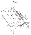
Classifications
-
- B—PERFORMING OPERATIONS; TRANSPORTING
- B41—PRINTING; LINING MACHINES; TYPEWRITERS; STAMPS
- B41C—PROCESSES FOR THE MANUFACTURE OR REPRODUCTION OF PRINTING SURFACES
- B41C1/00—Forme preparation
- B41C1/10—Forme preparation for lithographic printing; Master sheets for transferring a lithographic image to the forme
- B41C1/1041—Forme preparation for lithographic printing; Master sheets for transferring a lithographic image to the forme by modification of the lithographic properties without removal or addition of material, e.g. by the mere generation of a lithographic pattern
Landscapes
- Engineering & Computer Science (AREA)
- Manufacturing & Machinery (AREA)
- Photosensitive Polymer And Photoresist Processing (AREA)
- Materials For Photolithography (AREA)
- Printing Plates And Materials Therefor (AREA)
- Manufacture Or Reproduction Of Printing Formes (AREA)
- Rotary Presses (AREA)
- Inking, Control Or Cleaning Of Printing Machines (AREA)
Abstract
Description
- The present invention relates to a lithographic printing machine and a lithographic printing method. More specifically, the present invention relates to a lithographic printing machine capable of forming an image-forming layer on a plate cylinder for imaging of the lithographic printing machine, forming an image pattern on the image-forming layer by scanning exposure of an image by laser beams on the basis of digital data, making a printing plate, and capable of effecting printing excellent in resistance against scumming with the same printing plate on the same printing machine, and relates to a method of lithographic printing.
- Lithographic printing is a method of effecting printing by making use of an ink-receptive lipophilic area and an ink-nonreceptive hydrophilic or lipophobic area, and photosensitive lithographic printing plate precursors (PS plates) are now widely used as printing plate materials.
- PS plates comprising a metal support such as an aluminum plate having been subjected to surface-graining treatment, anodizing treatment and hydrophilization treatment having provided thereon a photosensitive layer comprising a photosensitive diazo resin, a photopolymerizable composition, a photo-crosslinkable composition, etc., have been put to practical use and are prevailingly used. The photosensitive layer of the nonimage area of these PS plates is removed by image exposure and development, and printing is performed by making use of the hydrophilicity of the support surface and the lipophilicity of the photosensitive layer of the image area.
- Further, so-called direct plate-making of directly making an offset printing plate from the original without using a film for plate-making is going into the field of general offset printing by making use of characteristics such as simplicity requiring no skill, labor saving, rapidity capable of expediting plate-making, etc. In particular, in recent years, various printing plate materials of novel types have been developed conjointly with the rapid progress of output systems, e.g., a pre-press system, an image setter, a laser printer, etc.
- These printing plate materials have the possibilities of application to so called plate-making on machine, i.e., plate-making by installing these printing plate materials on the plate cylinder of a printing machine and imagewise irradiating them with laser beams to make a printing plate. However, directplate-makingwhich requires development process with a developing solution is not good for plate-making on machine.
- As the printing plate precursor which requires no development process, there is disclosed in WO 99/37481 an ablation type positive lithographic printing plate precursor capable of recording by laser, which comprises a support having provided thereon a crosslinked hydrophilic layer, and thereon an ink-receptive surface layer of an organic polymer layer which contains one or more polymers and light/heat converting dyes capable of absorbing radiation of lasers, and the polymer layer absorbs radiation by ablation.
- Furthermore, as the trend of plate-making, direct plate-making on the same printing machine as that for printing work by the above-described lithographic printing machine of direct imaging on printing machine is proposed. For example, it is suggested in JP-A-9-99535 (the term "JP-A" as used herein means an "unexamined published Japanese patent application") to use a seamless cylinder (hence there is no space or groove) in place of plate cylinders so far been used for offset printing, cure a curable polymer coated on the seamless cylinder, and convert the affinity to a printing ink of the surface of the polymer by selectively irradiating the polymer surface with a laser. Since only the surface of the polymer is selectively converted by laser irradiation, the thickness and the uniformity of the polymer coating matter little. Aplate cylinder is cleaned after one printing work is finished. There is described in the patent specification that the cleaning need not be perfect because the surface of a plate cylinder itself is not exposed to ink.
- Such direct plate-making on printing machine has been developed for the purpose of providing a reusable surface layer which does not necessitate perfect cleaning of coating by the method of tolerating the remaining coating on the plate cylinder for imaging after cleaning and shortening the time required to make an image again, hence the method has the advantage of heat mode plate-making and printing method. However, with respect to heat mode sensitivity to irradiated laser rays, the above technique is not sufficient yet and, from the viewpoint of practical use, it has further been desired to achieve higher sensitization, to thereby increase a discriminating effect of an image area and a nonimage area (a discriminating property of hydrophobic property/hydrophilic property before and after exposure), and a method of direct plate-making on machine providing printed matters with no scumming.
- Accordingly, an object of the present invention is to provide a lithographic printing machine which makes it possible to directly form an image and make a printing plate on machine, to sufficiently maintain the discrimination of an image area and a nonimage area, and to provide printed matters without generating scumming even under severe printing conditions. Another object is to provide a lithographic printing method.
- As a result of eager investigations for achieving the above objects, the present inventors have found that printed matters generating no scumming even under severe printing conditions can be obtained using a polymer having a functional group which is converted from hydrophilic to hydrophobic by heating or by the heat generated by light/heat conversion as the heat-sensitive material for forming the image-forming layer (which is also referred to as a radiation-sensitive layer sometimes) on a lithographic printing machine equipped with a plate cylinder for imaging. Thus, the present invention has been achieved.
- That is, the present invention is as follows.
- (1) A lithographic printing machine comprising a plate cylinder for imaging, ablanket cylinder, an impression cylinder, and a film-coating unit, a film-hardening unit, an imaging unit and a cleaning unit each unit of which is adjacent to the plate cylinder for imaging, wherein an image-forming layer containing a polymer having a functional group which is crosslinkedby light or heat before imaging and a functional group which is converted from hydrophilic to hydrophobic by the heat generated by infrared ray irradiation is formed by the coating unit.
- (2) A lithographic printing method on a lithographic printing machine comprising a plate cylinder for imaging, a blanket cylinder, an impression cylinder, and a film-coating unit, a film-hardening unit, an imaging unit and a cleaning unit each unit of which is adjacent to the plate cylinder for imaging, which comprises the steps of at least (a) cleaning operation of cleaning said plate cylinder for imaging, (b) coating operation of coating an image-forming layer containing a polymer having a functional group converting from hydrophilic to hydrophobic by heating on the surface of said plate cylinder for imaging, (c) hardening operation of hardening said image-forming layer to a solid state, and (d) surface conversion operation of forming an image pattern due to hydrophilic/hydrophobic conversion corresponding to the digital data to be printed on the surface of said image-forming layer.
-
- According to the present invention, a printing plate can be made directly from digital data by the process comprising the steps of forming, as a radiation-sensitive material, a thin layer of a polymer having a functional group converting from hydrophilic to hydrophobic by heating or by the heat generated by light/heat conversion on the surface of the plate cylinder for imaging of a printing machine by means of a film-coating unit and a film-hardening unit each unit of which is adjacent to the plate cylinder, and recording with a thermal head or a laser radiating infrared rays equipped in the imaging unit.
- The radiation-sensitive layer according to the present invention largely converts from hydrophilic to hydrophobic to exhibit polarity conversion by scanning exposure of an image with laser beams in short time. As a result, the discrimination against inks occurs and an image area and a nonimage area are formed, thus a printing plate capable of providing printed matters not generating scumming can be made directly on machine without requiring special processes such as wet development or rubbing after image exposure even under severe printing conditions.
- In general, special care should be taken in film hardening about the storage stability after coating of radiation-sensitive materials, but in the present invention it is not necessary to give care to the storage stability, since hardening treatment can be performed immediately after direct coating on machine, thus the radiation-sensitive material of the present invention is suitable to direct plate-making on machine.
- Fig. 1 is a perspective view showing a lithographic printing machine capable of direct imaging and plate-making on machine of the present invention.
- A lithographic printing machine capable of imaging and plate-making on machine according to the present invention and a plate-making method will be described in detail below.
- A printing unit of a lithographic printing machine according to the present invention will be described with referring to Fig. 1. Fig. 1 is a perspective view showing an example of an apparatus for direct imaging and plate-making on machine of the present invention. Printing paper 1 in sheet or web (hereinafter referred to as merely "paper") is inserted between
impression cylinder 2 andblanket cylinder 3.Blanket cylinder 3 is in contact with imaging plate cylinder 4 taking the place of plate cylinder in ordinarily used printing machine, and functions as a means of transferring an ink-adhered image described later from imaging plate cylinder 4 to paper 1. The primary difference between imaging plate cylinder 4 and an ordinarily used plate cylinder (not shown in the figure) is that imaging plate cylinder 4 is a seamless cylinder. Therefore, as compared with an ordinarily used plate cylinder (not shown in the figure) having a long and narrow space to clamp a printing plate, seamless imaging plate cylinder 4 is not accompanied by vibration and can operate at higher speed. The film of a radiation-sensitive material having a functional group for image-forming described later coated on the peripheral surface of imaging plate cylinder 4 is adhered with an ink by water/ink-supplying system comprisingink fountain roller 5 andform roller 6.Ink fountain roller 5 andform roller 6 are integrated in a kind of ink-supplying system called "integrated" ink-supplying chain. In other method, the printing machine can be operated on water-free offset mode (or called "dry offset") without usingink fountain roller 5. The mechanism of the printing machine described above is conventionally well known. - Cleaning (washing) unit 7 is equipped in close vicinity to imaging plate cylinder 4. Cleaning unit 7 is to wipe off the ink, water and almost all the image-drawn radiation-sensitive layer on imaging plate cylinder 4 used in the previous printing work. Cleaning unit 7 is analogous to well-known "blanket washer" which is used in a modern printing machine for cleaning a blanket cylinder between one printing work and the nextprinting work, but differs in that sometimes a special solvent has to be added to cleaning unit 7 to dissolve almost all the image-drawn radiation-sensitive layer on the plate cylinder for imaging. According to the design of a modern printing machine , additional cleaning units can be equipped for cleaning a blanket cylinder and other cylinders.
- Straight rail 9 is fixed in parallel to imaging plate cylinder 4, and
carriage 8 is equipped which transfers to right and left along imaging plate cylinder 4 by the control ofmotor 11 andmaster screw 10 on straight rail 9. The movements of imaging plate cylinder 4 andmotor 11 are synchronized by means of a shaft encoder in an analogous mode to a drum type imaging unit. - Since a drum type imaging unit is well-known and on the market for long, the details of the synchronization and processing of image data (hereinafter sometimes referred to as merely "data") are not described furthermore.
Coating unit 12, hardeningunit 13 andimaging unit 14 are equipped oncarriage 8, and they are contrived to transfer to right and left along the overall width of imaging plate cylinder 4 together withcarriage 8. - As described above,
coating unit 12 sprays a polymer compound solution (a liquid polymer) of the radiation-sensitive material on imaging plate cylinder 4 after imaging plate cylinder 4 is cleaned (washed) by cleaning unit 7. Alternatively, such a polymer can be coated on imaging plate cylinder 4 by means of a roller as ink-coating. - Since an image should be drawn on the surface of the polymer coating within a short period of time after coating the polymer (generally less than 1 minute), the hardening of the liquid polymer to a solid state should be accelerated. The hardening of the polymer is accelerated by radiation or a hot blast generated by hardening
unit 13. It is possible to use ultraviolet rays to accelerate hardening, but the hardening by ultraviolet rays is not so desired, since it generates a crosslinked polymer which is difficult to be cleaned by cleaning unit 7. A radiation-sensitive layer is coated on imaging plate cylinder 4 in a thickness of generally from 1 to 10 µm. Hence, the amount of a polymer material to be hardened is small, thus the quantity of energy required in rapid hardening can be saved. - After polymer hardening, an image pattern (hereinafter sometimes referred to as merely "image" or "pattern") comprising an ink-receiving domain (hydrophobic) and an ink-repelling domain (hydrophilic) is formed on the surface of the hardened polymer by means of, e.g.,
imaging head 14 comprising multichannel laser heads. Aplenty of laser beams and relatively high power are required to draw images throughout the surface of the polymer in short time (within one or two minutes). A multi-beam laser imaging unit such asmultichannel laser head 14 is well known. The laser array disclosed in U.S. Patent 4,743,091 is an example of such multichannel laser heads. The required number of laser beams (hereinafter sometimes referred to as merely "beams") depends upon the necessary imaging time, the power of laser and the maximum engine speed of imaging plate cylinder 4. - During cleaning (washing and wiping), coating and imaging, the printing machine is on "printing operation off" mode (actuation mode of not operating printing). That is, imagingplate cylinder 4 is out of contact with any other cylinders during printing operation off mode (the same as the plate cylinders of usually used offset or lithographic printing machines on printing operation off mode) . When the imaging by imaging
unit 14 is finished, the printing machine is switched from printing operation off mode to printing operation on mode (actuation mode of operating printing), and an ink is adhered to the surface of the image-drawn radiation-sensitive layer (image-forming layer) on imaging plate cylinder 4 on usual offset mode or water-free offset mode. - Materials which are hydrophilic and suitable as the materials of seamless imaging plate cylinder 4 include Alumite, chromium, nickel, steel and alumina (Al2O3), and ceramics such as zirconia (ZrO2). Zirconia is particularly preferred because it has high durability, is hydrophilic, fireproofing, furthermore low in heat conductivity. If heat conductivity is low, the quantity of laser energy required to heat polymer coating 17 to induce chemical conversion of radiation-sensitive layer 17 can be saved. Since the converted polymer area 21 is hydrophilic and the surface of imaging plate cylinder 4 is also hydrophilic, the printing property is scarcely affected even when radiation-sensitive layer 17 is abraded.
- In the next place, a radiation-sensitive layer formed by coating on an imaging plate cylinder is described below. A radiation-sensitive material (a heat-sensitive image-forming material) of the present invention for use in a plate-making method by a printing machine capable of direct imaging and plate-making on machine is not particularly restricted so long as the material contains a polymer having the functional group which is converted from hydrophilic to hydrophobic by heating.
- The present invention is characterized in that the above-described radiation-sensitive material is used as the image-forming material on the imaging plate cylinder of a printing machine capable of direct imaging and plate-making on machine.
- Specific examples of the functional groups which are converted from hydrophilic to hydrophobic by heating include at least one functional group selected from a carboxylic acid group, a carboxylate group, a sulfonic acid group, and a phosphonic acid group. These carboxylic acid group, carboxylate group, sulfonic acid group, andphosphonic acid group are represented by the following formulae (1), (2), (3) and (4) respectively, preferably a carboxylic acid group, a carboxylate group, and a sulfonic acid group represented by formulae (1), (2) and (3) respectively, and particularly preferably a carboxylate group represented by formula (2).


 wherein X is selected from -CO-, -SO-, -SO2-, and elements belonging to Group 15 and Group 16 of the Periodic Table; -L- represents a divalent connecting group; R1 and R2, which may be the same or different, each represents a monovalent group; and M represents a cation selected from the group consisting of an alkali metal, an alkaline earth metal and onium.
- R1 and R2 each represents a monovalent nonmetallic atomic group containing a hydrogen atom, and preferred examples include a halogen atom (e.g., -F, -Br, -Cl, -I), a hydroxyl group, an alkyl group, an alkoxyl group, an aryloxy group, a mercapto group, an alkylthio group, an arylthio group, an alkyldithio group, an aryldithio group, an amino group, an N-alkylamino group, an N,N-diarylamino group, an N-alkyl-N-arylamino group, an acyloxy group, a carbamoyloxy group, an N-alkylcarbamoyloxy group, an N-arylcarbamoyloxy group, an N,N-dialkylcarbamoyloxy group, an N,N-diarylcarbamoyloxy group, an N-alkyl-N-arylcarbamoyloxy group, an alkylsulfoxy group, an arylsulfoxy group, an acylthio group, an acylamino group, an N-alkylacylamino group, an N-arylacylamino group, a ureido group, an N'-alkylureido group, an N',N'-dialkylureido group, an N'-arylureido group, an N',N'-diarylureido group, an N'-alkyl-N'-arylureido group, an N-alkylureido group, an N-arylureido group, an N'-alkyl-N-alkylureido group, an N'-alkyl-N-arylureido group, an N',N'-dialkyl-N-alkylureido group, an N',N'-dialkyl-N-arylureido group, an N'-aryl-N-alkylureido group, an N'-aryl-N-arylureido group, an N',N'-diaryl-N-alkylureido group, an N' ,N'-diaryl-N-arylureido group, an N'-alkyl-N'-aryl-N-alkylureido group, an N'-alkyl-N'-aryl-N-arylureido group, an alkoxycarbonylamino group, an aryloxycarbonylamino group, an N-alkyl-N-alkoxycarbonylamino group, an N-alkyl-N-aryloxy-carbonylamino group, an N-aryl-N-alkoxycarbonylamino group, an N-aryl-N-aryloxycarbonylamino group, a formyl group, an acyl group, a carboxyl group, an alkoxycarbonyl group, an aryloxycarbonyl group, a carbamoyl group, an N-alkylcarbamoyl group, an N,N-dialkylcarbamoyl group, an N-arylcarbamoyl group, an N,N-diarylcarbamoyl group, an N-alkyl-N-arylcarbamoyl group, an alkylsulfinyl group, an arylsulfinyl group, an alkylsulfonyl group, an arylsulfonyl group, a sulfo group (-SO3H) and a conjugate base group thereof (hereinafter referred to as a sulfonato group) , an alkoxysulfonyl group, an aryloxysulfonyl group, a sulfinamoyl group, an N-alkylsulfinamoyl group, an N,N-dialkylsulfinamoyl group, an N-arylsulfinamoyl group, an N,N-diarylsulfinamoyl group, an N-alkyl-N-arylsulfinamoyl group, a sulfamoyl group, an N-alkylsulfamoyl group, an N,N-dialkylsulfamoyl group, an N-arylsulfamoyl group, an N,N-diarylsulfamoyl group, an N-alkyl-N-arylsulfamoyl group, a phosphono group (-PO3H2) and a conjugate base group thereof (hereinafter referred to as a phosphonato group), a dialkylphosphono group (-PO3(alkyl)2), a diarylphosphono group (-PO3(aryl)2), an alkylarylphosphono group (-PO3 (alkyl) (aryl)), a monoalkylphosphono group (-PO3H(alkyl)) and a conjugate base group thereof (hereinafter referred to as an alkylphosphonato group) , a monoarylphosphono group (-PO3H(aryl)) and a conjugate base group thereof (hereinafter referred to as an arylphosphonato group), a phosphonoxy group (-OPO3H2) and a conjugate base group thereof (hereinafter referred to as a phosphonatoxy group), a dialkylphosphonoxy group (-OPO3(alkyl)2), a diarylphosphonoxy group (-OPO3(aryl)2), an alkylarylphosphonoxy group (-OPO3(alkyl)(aryl)), a monoalkylphosphonoxy group (-OPO3H(alkyl)) and a conjugate base group thereof (hereinafter referred to as an alkylphosphonatoxy group), a mono-arylphosphonoxy group (-OPO3H(aryl)) and a conjugate base group thereof (hereinafter referred to as an arylphosphonatoxy group), a cyano group, a nitro group, an aryl group, an alkenyl group, and an alkynyl group.
- Preferred examples of the alkyl groups are straight chain, branched or cyclic alkyl groups having from 1 to 20 carbon atoms each of which may have a substituent, and specific examples include a methyl group, an ethyl group, a propyl group, a butyl group, a pentyl group, a hexyl group, a heptyl group, an octyl group, a nonyl group, a decyl group, a undecyl group, a dodecyl group, a tridecyl group, a hexadecyl group, an octadecyl group, an eicosyl group, an isopropyl group, an isobutyl group, an s-butyl group, a t-butyl group, an isopentyl group, a neopentyl group, a 1-methylbutyl group, an isohexyl group, a 2-ethylhexyl group, a 2-methylhexyl group, a cyclohexyl group, a cyclopentyl group, and a 2-norbornyl group. Of these groups, a straight chain alkyl group having from 1 to 12 carbon atoms, a branched alkyl group having from 3 to 12 carbon atoms, and a cyclic alkyl group having from 5 to 10 carbon atoms are more preferred.
- Examples of the substituents of the substituted alkyl groups are monovalent nonmetallic atomic groups exclusive of a hydrogen atom, and preferred examples include a halogen atom (-F, -Br, -Cl, -I) , a hydroxyl group, an alkoxyl group, an aryloxy group, a mercapto group, an alkylthio group, an arylthio group, an alkyldithio group, an aryldithio group, an amino group, an N-alkylamino group, an N,N-diarylamino group, an N-alkyl-N-arylamino group, an acyloxy group, a carbamoyloxy group, an N-alkylcarbamoyloxy group, an N-arylcarbamoyloxy group, an N,N-dialkylcarbamoyloxy group, an N,N-diaryl-carbamoyloxy group, an N-alkyl-N-arylcarbamoyloxy group, an alkylsulfoxy group, an arylsulfoxy group, an acylthio group, an acylamino group, an N-alkylacylamino group, an N-arylacylamino group, a ureido group, an N'-alkylureido group, an N',N'-dialkylureido group, an N'-arylureido group, an N',N'-diarylureido group, an N'-alkyl-N'-arylureido group, an N-alkylureido group, an N-arylureido group, an N'-alkyl-N-alkylureido group, an N'-alkyl-N-arylureido group, an N',N'-dialkyl-N-alkylureido group, an N',N'-dialkyl-N-arylureido group, an N'-aryl-N-alkylureido group, an N'-aryl-N-arylureido group, an N',N'-diaryl-N-alkylureido group, an N',N'-diaryl-N-arylureido group, an N'-alkyl-N'-aryl-N-alkylureido group, an N'-alkyl-N'-aryl-N-arylureido group, an alkoxycarbonylamino group, an aryloxycarbonylamino group, an N-alkyl-N-alkoxycarbonylamino group, an N-alkyl-N-aryloxy-carbonylamino group, an N-aryl-N-alkoxycarbonylamino group, an N-aryl-N-aryloxycarbonylamino group, a formyl group, an acyl group, a carboxyl group, an alkoxycarbonyl group, an aryloxycarbonyl group, a carbamoyl group, an N-alkylcarbamoyl group, an N,N-dialkylcarbamoyl group, an N-arylcarbamoyl group, an N,N-diarylcarbamoyl group, an N-alkyl-N-arylcarbamoyl group, an alkylsulfinyl group, an arylsulfinyl group, an alkylsulfonyl group, an arylsulfonyl group, a sulfo group (-SO3H) and a conjugate base group thereof (hereinafter referred to as a sulfonato group), an alkoxysulfonyl group, an aryloxysulfonyl group, a sulfinamoyl group, an N-alkylsulfinamoyl group, an N,N-dialkylsulfinamoyl group, an N-arylsulfinamoyl group, an N,N-diarylsulfinamoyl group, an N-alkyl-N-arylsulfinamoyl group, a sulfamoyl group, an N-alkylsulfamoyl group, an N,N-dialkylsulfamoyl group, an N-arylsulfamoyl group, an N,N-diarylsulfamoyl group, an N-alkyl-N-arylsulfamoyl group, a phosphono group (-PO3H2) and a conjugate base group thereof (hereinafter referred to as a phosphonato group), a dialkylphosphono group (-PO3(alkyl)2), a diarylphosphono group (-PO3(aryl)2), an alkylarylphosphono group (-PO3(alkyl) (aryl)), a monoalkylphosphono group (-PO3H (alkyl)) and a conjugate base group thereof (hereinafter referred to as an alkylphosphonato group) , a monoarylphosphono group (-PO3H(aryl)) and a conjugate base group thereof (hereinafter referred to as an arylphosphonato group) , a phosphonoxy group (-OPO3H2) and a conjugate base group thereof (hereinafter referred to as a phosphonatoxy group), a dialkylphosphonoxy group (-OPO3(alkyl)2), a diarylphosphonoxy group (-OPO3(aryl)2), an alkylarylphosphonoxy group (-OPO3(alkyl)(aryl)), a monoalkylphosphonoxy group (-OPO3H(alkyl)) and a conjugate base group thereof (hereinafter referred to as an alkylphosphonatoxy group), a monoaryl-phosphonoxy group (-OPO3H(aryl)) and a conjugate base group thereof (hereinafter referred to as an arylphosphonatoxy group), a cyano group, a nitro group, an aryl group, an alkenyl group, and an alkynyl group.
- As the specific examples of the alkyl groups in these substituents, the above-described alkyl groups can be exemplified, and as the specific examples of the aryl groups in these substituents, a phenyl group, a biphenyl group, a naphthyl group, a tolyl group, a xylyl group, a mesityl group, a cumenyl group, a chlorophenyl group, a bromophenyl group, a chloromethylphenyl group, a hydroxyphenyl group, a methoxyphenyl group, an ethoxyphenyl group, a phenoxyphenyl group, an acetoxyphenyl group, a benzoyloxyphenyl group, a methylthiophenyl group, a phenylthiophenyl group, a methylaminophenyl group, a dimethylaminophenyl group, an acetylaminophenyl group, a carboxyphenyl group, a methoxycarbonylphenyl group, an ethoxycarbonylphenyl group, a phenoxycarbonylphenyl group, an N-phenylcarbamoylphenyl group, a cyanophenyl group, a sulfophenyl group, a sulfonatophenyl group, a phosphonophenyl group and a phosphonatophenyl group can be exemplified. As the examples of the alkenyl groups in these substituents, a vinyl group, a 1-propenyl group, a 1-butenyl group, a cinnamyl group, and a 2-chloro-1-ethenyl group can be exemplified. As the examples of the alkynyl groups, an ethynyl group, a 1-propynyl group, a 1-butynyl group and a trimethylsilylethynyl group can be exemplified. As G1 in the acyl group (G1CO-), a hydrogen atom and the above-described alkyl groups and aryl groups can be exemplified. Of these substituents , more preferred groups include a halogen atom (-F, -Br, -Cl, -I) , an alkoxyl group, an aryloxy group, an alkylthio group, an arylthio group, an N-alkylamino group, an N, N-dialkylamino group, an acyloxy group, an N-alkylcarbamoyloxy group, an N-arylcarbamoyloxy group, an acylamino group, a formyl group, an acyl group, a carboxyl group, an alkoxycarbonyl group, an aryloxycarbonyl group, a carbamoyl group, an N-alkylcarbamoyl group, an N,N-dialkylcarbamoyl group, an N-arylcarbamoyl group, an N-alkyl-N-arylcarbamoyl group, a sulfo group, a sulfonato group, a sulfamoyl group, an N-alkylsulfamoyl group, an N,N-dialkylsulfamoyl group, an N-arylsulfamoyl group, an N-alkyl-N-arylsulfamoyl group, a phosphono group, a phosphonato group, a dialkylphosphono group, a diarylphosphono group, a monoalkylphosphono group, an alkylphosphonato group, a monoarylphosphono group, an arylphosphonato group, a phosphonoxy group, a phosphonatoxy group, an aryl group, and an alkenyl group.
- On the other hand, as the alkylene groups in the substituted alkyl groups, the alkylene groups obtained by removing any one hydrogen atom on the above-described alkyl groups having from 1 to 20 carbon atoms to make divalent organic residues canbe exemplified, preferably a straight chain alkylene group having from 1 to 12 carbon atoms, a branched alkylene group having from 3 to 12 carbon atoms, and a cyclic alkylene group having from 5 to 10 carbon atoms. Specific examples of the preferred substituted alkyl groups obtained by combining the above substituents and alkylene groups include a chloromethyl group, a bromomethyl group, a 2-chloroethyl group, a trifluoromethyl group, a methoxymethyl group, a methoxyethoxyethyl group, an allyloxymethyl group, a phenoxymethyl group, a methylthiomethyl group, a tolylthio-methyl group, an ethylaminoethyl group, a diethylaminopropyl group, a morpholinopropyl group, an acetyloxymethyl group, a benzoyloxymethyl group, an N-cyclohexylcarbamoyloxyethyl group, an N-phenylcarbamoyloxyethyl group, an acetylaminoethyl group, an N-methylbenzoylaminopropyl group, a 2-oxoethyl group, a 2-oxopropyl group, a carboxypropyl group, a methoxycarbonylethyl group, an allyloxycarbonylbutyl group, a chlorophenoxycarbonylmethyl group, a carbamoylmethyl group, an N-methylcarbamoylethyl group, an N,N-dipropylcarbamoylmethyl group, an N-(methoxyphenyl) carbamoylethyl group, an N-methyl-N-(sulfophenyl)carbamoylmethyl group, a sulfobutyl group, a sulfonatobutyl group, a sulfamoylbutyl group, an N-ethylsulfamoylmethyl group, an N,N-dipropylsulfamoylpropyl group, an N-tolylsulfamoylpropyl group, an N-methyl-N-(phosphonophenyl) sulfamoyloctyl group, a phosphonobutyl group, a phosphonatohexyl group, a diethylphosphonobutyl group, a diphenylphosphonopropyl group, a methylphosphonobutyl group, a methylphosphonatobutyl group, a tolylphosphonohexyl group, a tolylphosphonatohexyl group, a phosphonoxypropyl group, a phosphonatoxybutyl group, a benzyl group, a phenethyl group, an α-methylbenzyl group, a 1-methyl-1-phenylethyl group, a p-methylbenzyl group, a cinnamyl group, an allyl group, a 1-propenylmethyl group, a 2-butenyl group, a 2-methylallyl group, a 2-methylpropenyl-methyl group, a 2-propynyl group, a 2-butynyl group, and a 3-butynyl group.
- When R1 and R2 each represents an aryl group, the aryl groups include a condensed ring formed by 1 to 3 benzene rings and a condensed ring formed by a benzene ring and a 5-membered unsaturated ring, and specific examples thereof include a phenyl group, a naphthyl group, an anthryl group, a phenanthryl group, an indenyl group, an acenaphthenyl group, and a fluorenyl group. Of these groups, a phenyl group and a naphthyl group are more preferred. Heterocyclic aryl groups are included in the aryl group besides the above carbocyclic aryl groups. As the heterocyclic aryl groups, a pyridyl group, a furyl group, those containing from 3 to 20 carbon atoms and from 1 to 5 hetero atoms, e.g., a quinolyl group, a benzofuryl group, a thioxanthone group, and a carbazole group condensed with a benzene ring are used.
- As the substituted aryl groups, those having, as the substituents, monovalent nonmetallic atomic groups exclusive of a hydrogen atom on the ring-forming carbon atoms of the above-described aryl groups are used. As preferred examples of the substituents, the above-described alkyl groups, the substituted alkyl groups, and the groups described above as the examples of the substituents for the substituted alkyl groups can be exemplified. Preferred specific examples of such substituted aryl groups include a biphenyl group, a tolyl group, a xylyl group, a mesityl group, a cumenyl group, a chlorophenyl group, a bromophenyl group, a fluorophenyl group, a chloromethylphenyl group, a trifluoromethylphenyl group, a hydroxyphenyl group, a methoxyphenyl group, a methoxyethoxyphenyl group, an allyloxyphenyl group, a phenoxyphenyl group, a methylthiophenyl group, a tolylthio-phenyl group, an ethylaminophenyl group, a diethylaminophenyl group, a morpholinophenyl group, an acetyloxyphenyl group, a benzoyloxyphenyl group, an N-cyclohexylcarbamoyloxyphenyl group, an N-phenylcarbamoyloxyphenyl group, an acetylaminophenyl group, an N-methylbenzoylaminophenyl group, a carboxyphenyl group, a methoxycarbonylphenyl group, an allyloxy-carbonylphenyl group, a chlorophenoxycarbonylphenyl group, a carbamoylphenyl group, an N-methylcarbamoylphenyl group, an N,N-dipropylcarbamoylphenyl group, an N-(methoxyphenyl)-carbamoylphenyl group, an N-methyl-N-(sulfophenyl)carbamoylphenyl group, a sulfophenyl group, a sulfonatophenyl group, a sulfamoylphenyl group, an N-ethylsulfamoylphenyl group, an N,N-dipropylsulfamoylphenyl group, an N-tolylsulfamoylphenyl group, an N-methyl-N-(phosphonophenyl)sulfamoylphenyl group, a phosphonophenyl group, a phosphonatophenyl group, a diethylphosphonophenyl group, a diphenylphosphonophenyl group, a methylphosphonophenyl group, a methylphosphonatophenyl group, a tolylphosphonophenyl group, a tolylphosphonatophenyl group, an allyl group, a 1-propenylmethyl group, a 2-butenyl group, a 2-methylallylphenyl group, a 2-methylpropenylphenyl group, a 2-propynylphenyl group, a 2-butynylphenyl group, and a 3-butynylphenyl group.
- Specific preferred examples represented by X include -O-, -S-, -Se-, -CO-, -SO-, and -SO2-, and -CO-, -SO- and -SO2- are particularly preferred of these in view of heat reactivity.
- The divalent connecting group represented by L is preferably a group composed of nonmetallic atoms selected from from 1 to 60 carbon atoms, from 0 to 10 nitrogen atoms, from 0 to 50 oxygen atoms, from 1 to 100 hydrogen atoms, and from 0 to 20 sulfur atoms . As more specific examples of the connecting groups, those comprised of the following structural units in combination can be exemplified.


- Mis not particularly restricted so long as it represents a cation but it is preferably a monovalent to tetravalent metal cation or an ammonium salt represented by the following formula (5):wherein R7, R8, R9 and R10, which may be the same or different, each represents a monovalent group.

- The monovalent to tetravalent metal cation represented by M is selected from Li+, Na+, K+, Rb+, Cs+, Fr+, Be2+, Mg2+, Ca2+, Sr2+, Ba2+, Ra2+, Cu+, Cu2+, Ag+, Zn2+, Al3+, Fe2+, Fe3+, Co2+, Ni2+, Ti4+ and Zr4+, more preferably Li+, Na+, K+, Rb+, Cs+, Fr+, Cu+ and Ag+.
- In the ammonium ion represented by formula (5), specific examples of the groups represented by R7, R8, R9 and R10 are the same as the groups represented by R1 and R2 described above. Specific examples of the ammonium ions represented by formula (5) are shown below.


- Specific examples of the functional groups represented by formulae (1) to (4) are shown below, but the present invention is not limited thereto.


- Crosslinking methods for preparing polymers three dimensionally crosslinked and having the above-described functional group (a) which polymers are to be contained in a recording layer of the lithographic printing plate precursor used in the present invention are not particularly restricted, and polymers obtained by a sol/gel reaction, photo-crosslinking reaction, and thermal-crosslinking reaction can be used, for instance.
- Polymers obtained by a sol/gel reaction are described below.
- A polymer obtained by a sol/gel reaction is a reaction product of (i) a compound having, in the same molecule, functional group (a), and (b) at least any functional group selected from the group consisting of -OH, -NH2, -NH-CO-R3, and -Si(OR4)3 (wherein R3 and R4 each represents an alkyl group or an aryl group, and when R3 and R4 are both contained in the compound containing these functional groups, they may be the same or different), with (ii) a polymerizable compound by hydrolysis represented by the following formula (6):
- In the above compound (i), functional group (a) whose hydrophilic property is converted by decarbonization by at least radiation irradiation or by heat carries the image signal-responding function and records images as image signals in the molecule in the form of conversion to hydrophobic by responding to at least either directly radiation or heat. On the other hand, functional group (b) present in the same molecule has the function of bonding compound (i) to the peripheral matrix. Specifically, functional group (b) reacts with at least any of (ii) a hydrolysis polymerizable compound represented by formula (6) or the hydrolyzed product thereof, and hydrolysis polymerizable compound (ii) is polymerized by hydrolysis, thereby an image-recording matrix consisting of bonding chains of an inorganic compound is formed in the film and crosslinked, thus an image recorded is strengthened.
- Functional group (b) in compound (i) is a group carrying the function of bonding compound (i) to the matrix of compound (ii), and any well-known functional groups can be used as functional group (b) so long as they have the property of reacting with the alkyl group, aryl group, alkoxyl group, or aryloxy group in compound (ii), or the hydroxyl group by hydrolysis or central metallic atoms to form bonding, and can coexist with functional group (a) in the same molecule. A functional group forming bonding by the reaction with a hydroxyl group or an alkoxyl group is particularly preferred. Of these, a functional group selected from the group consisting of -OH, -NH2, -NH-CO-R3, and -Si(OR4)3 (wherein R3 and R4 each represents an alkyl group or an aryl group, and when R3 and R4 are both contained in the compound containing these functional groups, they may be the same or different) is preferably used in the present invention.
- When functional group (b) represents -NH-CO-R3 and/or -Si(OR4)3, R3 and R4 each preferably represents an alkyl group having from 1 to 10 carbon atoms or an aryl group having from 6 to 20 carbon atoms, and they may be substituted with a halogen atom such as chlorine, an alkoxyl group such as a methoxy group or an alkoxycarbonyl group such as a methoxycarbonyl group. As the specific examples of -NH-CO-R3, -NH-CO-CH3 and -NH-CO-C2H5 can be exemplified, and as the specific examples of -Si(OR4)3, -Si(OCH3)3 and -Si(OC2H5)3 can be exemplified.
- The synthesis method of compound (i) is not particularly restricted, and compound (i) can be obtained by radical polymerization of a monomer having functional group (a) and a monomer having functional group (b). As such compound (i), copolymers comprising one kind of monomer having functional group (a) and one kind of monomer having functional group (b) may be used, but copolymers in which both monomers comprise two or more kinds or either one monomer comprises two or more kinds, or copolymers comprising these monomers and other monomers can be used.
- Specific examples of the monomers having a functional group represented by the above-described formula (1), (2), (3) or (4) which are preferably used in the synthesis of compound (i) are shown below, but the present invention is not limited thereto.


- As other monomers, monomers having crosslinking reactivity such as glycidyl methacrylate, N-methylol-methacrylamide and 2-isocyanate ethyl acrylate are preferably used.
- In addition, as other monomers for use in the copolymers, well-known monomers, e.g., acrylates, methacrylates, acrylamides, methacrylamides, vinyl esters, styrenes, acrylic acid, methacrylic acid, acrylonitrile, maleic anhydride, and maleic acid imide can also be exemplified.
- Specific examples of acrylates include methyl acrylate, ethyl acrylate, (n- or i-)propyl acrylate, (n-, i-, sec- or t-)butyl acrylate, amyl acrylate, 2-ethylhexyl acrylate, dodecyl acrylate, chloroethyl acrylate, 2-hydroxyethyl acrylate, 2-hydroxypropyl acrylate, 5-hydroxypentyl acrylate, cyclohexyl acrylate, allyl acrylate, trimethylolpropane monoacrylate, pentaerythritol monoacrylate, benzyl acrylate, methoxybenzyl acrylate, chlorobenzyl acrylate, hydroxybenzyl acrylate, hydroxyphenethyl acrylate, dihydroxyphenethyl acrylate, furfuryl acrylate, tetrahydrofurfuryl acrylate, phenyl acrylate, hydroxyphenyl acrylate, chlorophenyl acrylate, sulfamoylphenyl acrylate, and 2-(hydroxy-phenylcarbonyloxy)ethyl acrylate.
- Specific examples of methacrylates include methyl methacrylate, ethyl methacrylate, (n- or i-)propyl methacrylate, (n-, i-, sec- or t-)butyl methacrylate, amyl methacrylate, 2-ethylhexyl methacrylate, dodecyl methacrylate, chloroethyl methacrylate, 2-hydroxyethyl methacrylate, 2-hydroxypropyl methacrylate, 5-hydroxypentyl methacrylate, cyclohexyl methacrylate, allyl methacrylate, trimethylolpropane monomethacrylate, pentaerythritol monomethacrylate, glycidyl methacrylate, benzylmethacrylate, methoxybenzyl methacrylate, chlorobenzyl methacrylate, hydroxybenzyl methacrylate, hydroxyphenethyl methacrylate, dihydroxyphenethyl methacrylate, furfuryl methacrylate, tetrahydrofurfuryl methacrylate, phenylmethacrylate, hydroxyphenylmethacrylate, chlorophenyl methacrylate, sulfamoylphenyl methacrylate, and 2-(hydroxyphenylcarbonyloxy)ethyl methacrylate.
- Specific examples of acrylamides include acrylamide, N-methylacrylamide, N-ethylacrylamide, N-propylacrylamide, N-butylacrylamide, N-benzylacrylamide, N-hydroxyethylacryl-amide, N-phenylacrylamide, N-tolylacrylamide, N-(hydroxyphenyl)acrylamide, N-(sulfamoylphenyl)acrylamide, N-(phenylsulfonyl)acrylamide, N-(tolylsulfonyl)acrylamide, N,N-dimethylacrylamide, N-methyl-N-phenylacrylamide, and N-hydroxyethyl-N-methylacrylamide.
- Specific examples of methacrylamides include methacrylamide, N-methylmethacrylamide, N-ethylmethacryl-amide, N-propylmethacrylamide, N-butylmethacrylamide, N-benzylmethacrylamide, N-hydroxyethylmethacrylamide, N-phenylmethacrylamide, N-tolylmethacrylamide, N-(hydroxyphenyl)methacrylamide, N-(sulfamoylphenyl)methacrylamide, N- (phenyl-sulfonyl)methacrylamide, N-(tolylsulfonyl)methacrylamide, N,N-dimethylmethacrylamide, N-methyl-N-phenylmethacrylamide, and N-hydroxyethyl-N-methylmethacrylamide.
- Specific examples of vinyl esters include vinyl acetate, vinyl butyrate, and vinyl benzoate.
- Specific examples of styrenes include styrene, methylstyrene, dimethylstyrene, trimethylstyrene, ethylstyrene, propylstyrene, cyclohexylstyrene, chloromethylstyrene, trifluoromethylstyrene, ethoxymethylstyrene, acetoxymethylstyrene, methoxystyrene, dimethoxystyrene, chlorostyrene, dichlorostyrene, bromostyrene, iodostyrene, fluorostyrene, and carboxystyrene.
- Of these other monomers, acrylates, methacrylates, acrylamides, methacrylamides, vinyl esters, styrenes, acrylic acid, methacrylic acid, and acrylonitrile each having 20 or less carbon atoms are especially preferably used.
- The mixing ratio of the monomer having functional group (a) and the monomer having functional group (b) for use in the synthesis of the above-described copolymers is preferably from 10/90 to 99/1, more preferably from 30/70 to 97/3, in weight ratio.
- When other monomers are used in the copolymers, the ratio of other monomers to the total of the monomer having functional group (a) and the monomer having functional group (b) for use in the synthesis of the copolymers is preferably from 5 to 99 wt%, more preferably from 10 to 95 wt%.
- Specific examples of compounds (i) for use in the present invention are shown below. The numeral values on the right lower side of the parentheses in each structural formula show the copolymerization ratio (molar ratio).


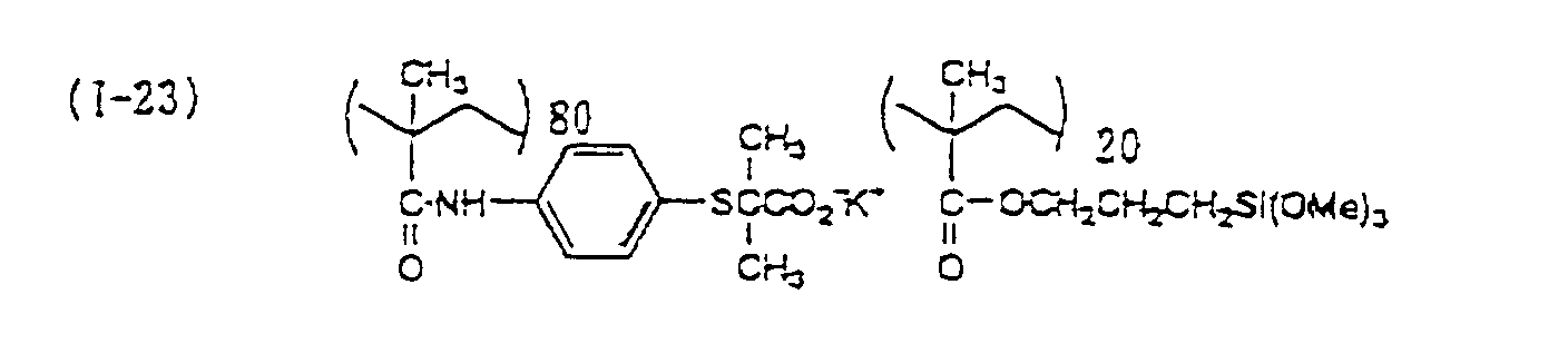

- In the next place, (ii) a polymerizable compound by hydrolysis represented by the following formula (6) (hereinafter also referred to as merely "compound (ii)") for use for sol/gel reaction with compound (i) is described below.
- Compound (ii) or a hydrolyzed product thereof forms a matrix of an inorganic oxide in the film by hydrolysis polymerization and reacts with functional group (b) in compound (i), also forms porous organic and inorganic composites (reaction products) by the adsorption onto water-insoluble solidparticles described later, thus the crosslinking structure becomes dense and the film strength is increased throughout, and the discrimination of an image area and a nonimage area is improved as well.
- Further, the later-described adsorption of compound (ii) onto water-insoluble particles is presumably due to chemical adsorption or physical adsorption or both of them. Compound (ii) may have functional group (b') for this adsorption.
- Since functional group (b') is almost the same as functional group (b), functional group (b') is not further described below.
- As the compounds containing aluminum in compound (ii), e.g., trimethoxy aluminate, triethoxy aluminate, tripropoxy aluminate, and tetraethoxy aluminate can be exemplified. As the compounds containing titanium, e.g., trimethoxy titanate, tetramethoxy titanate, triethoxy titanate, tetraethoxy titanate, tetrapropoxy titanate, chlorotrimethoxy titanate, chlorotriethoxy titanate, ethyltrimethoxy titanate, methyltriethoxy titanate, ethyltriethoxy titanate, diethyldiethoxy titanate, phenyltrimethoxy titanate, and phenyltriethoxy titanate can be exemplified. As the compounds containing zirconium, e.g., the compounds containing zirconate corresponding to those containing titanium, i.e., compounds replacing titanate with zirconate, can be exemplified.
- As the compounds containing silicon in compound (ii), e.g., trimethoxysilane, triethoxysilane, tripropoxysilane, tetramethoxysilane, tetraethoxysilane, tetrapropoxysilane, methyltrimethoxysilane, ethyltrimethoxysilane, propyltrimethoxysilane, methyltriethoxysilane, ethyltriethoxysilane, propyltriethoxysilane, dimethyldimethoxysilane, dimethyldiethoxysilane, diethyldiethoxysilane, γ-chloropropyltriethoxysilane, γ-mercaptopropyltrimethoxysilane, γ-mercaptopropyltriethoxysilane, γ-aminopropyltriethoxysilane, phenyltrimethoxysilane, phenyltriethoxysilane, phenyltripropoxysilane, diphenyldimethoxysilane, and diphenyldiethoxysilane can be exemplified. Of these, tetramethoxysilane, tetraethoxysilane, methyltrimethoxysilane, ethyltrimethoxysilane, methyltriethoxysilane, ethyltriethoxysilane, dimethyldiethoxysilane, phenyltrimethoxysilane, phenyltriethoxysilane, diphenyldimethoxysilane, and diphenyldiethoxysilane are particularly preferred.
- Compound (ii) may be used alone or two or more kinds may be used in combination. Compound (ii) may be condensed by dehydration after partial hydrolysis. If necessary, trialkylmonoalkoxysilane can be added to compound (ii) for adjusting the physical properties of the reaction product. Although compound (ii) is a compound constituting an inorganic phase in the material of the recording layer of the present invention, for increasing the storage stability of the recording layer material in the state of a solution before being coated on the substrate of the lithographic printing plate precursor of the present invention, it is effective to protect the active metallic hydroxyl group of the inorganic polymer obtained by partial hydrolysis polymerization of compound (ii), e.g., a silanol group (Si-OH). The protection of a silanol group can be effected by esterifying the silanol group (Si-OR) with higher alcohols, e.g., tert-butanol and iso-propyl alcohol. Specifically, the protection can be performed by adding the foregoing alcohols to the organic phase. According to the nature of the inorganic phase, the storage stability of compound (ii) can be further increased at this time by dehydrating the inorganicphase, for example, by means of heating the inorganic phase and distilling off the eliminatedwater. When acids or bases capable of being catalysts of the hydrolysis polymerization, e.g., hydrochloric acid or ammonia, are present in the inorganic phase, it is also generally effectual to lower the concentration of them. This is easily performed by neutralizing the inorganic phase with an acid or a base.
- Compound (ii) is preferably used in an amount of from 3 to 95 wt%, more preferably from 10 to 80 wt%, based on the total solid contents of the recording layer of the lithographic printing plate precursor used in the present invention.
- In the next place, polymers which are obtained by photopolymerization or thermal polymerization reaction to be added, as the crosslinked polymer having functional group (a) , to the recording layer of the lithographic printing plate precursor used in the present invention, other than those obtained by a sol/gel reaction, are described below.
- There are methods by photo-dimerization and radical photopolymerization in photo-crosslinking. There are methods by epoxy crosslinking, isocyanate crosslinking and methylol crosslinking in thermal-crosslinking. In any of these methods, a crosslinking reactive group is incorporated into a polymer and crosslinking is performed by the reaction of the polymer by itself or with a monomer.
- In photo-dimerization reaction, crosslinking reaction can be caused by light absorption of the functional group of the polymer itself or by light irradiation using a photosensitizer.
- In radical photopolymerization crosslinking, crosslinking reaction can be caused by light irradiation using a well-known photopolymerization initiator.
- In thermal-crosslinking such as epoxy crosslinking, isocyanate crosslinking and methylol crosslinking, crosslinking is effected by heating using a catalyst such as acids and organic metals.
- Of the photo-crosslinking and thermal-crosslinking methods, the former is more effective in that crosslinking is effected without heating and functional group (a) which is converted from hydrophilic to hydrophobic due to any of acids, radiation and heat can be protected.
- A polymer which is crosslinked by a photo-crosslinking reaction can be obtained by copolymerizing a monomer having a photo-crosslinkable functional group, which is also known as a photo-curing functional group , and a monomer having functional group (a) whose hydrophilic property is converted due to any of acids, radiation and heat.
- Apolymer which is crosslinkedby a thermal-crosslinking reaction can be obtained by copolymerizing a monomer having a thermal-crosslinkable group and a monomer having functional group (a) whose hydrophilic property is converted due to any of acids, radiation and heat.
- "Thermal- and/or photo-curing functional groups" are functional groups which undergo a setting reaction of a resin due to at least either heat or light.
- As specific photo-curing functional groups, the functional groups used in photosensitive resins and the like conventionally well-known as photosetting resins exemplified in Inui and Nagamatsu, Kankosei Kobunshi (Photosensitive High Polymers), Kodansha Publishing Co., Ltd. (1977), Tsunoda, Shin-Kankosei Jushi (New Photosensitive Resins), Insatsu Gakkai, Publishing Division (1981), G.E. Green and B.P. Strak, J. Macro . Sci. Reas. Macro. Chem., C21 (2), pp. 187 to 273 (1981-82), and C.G. Rattey, Photopolymerization of Surface Coatings, A. Wiley Interscience Pub. (1982) can be used in the present invention.
- Furthermore, as the thermosetting functional groups in the present invention, the functional groups exemplified, e.g., in Tsuyoshi Endo, Netsu Kokasei Kobunshi no Seimitsuka (Making into Precision of Thermosetting High C.M.C. Publishing Co., Ltd. (1986), Yuji Harasaki, Saishin Binder Gijutsu Binran (Handbook of the Latest Techniques of Binders) , Chap. II-1, Sogo Gijutsu Center (1985), Takayuki Ohtsu, Acryl Jushi no Gosei·Sekkei to Shin Yoto Kaihatsu (Syntheses and Designs of Acrylate Resins and Opening up of New Avenues of Use), Publishing Division of Chubu-Keiei-Kaihatsu Center (1985), and Eizo Ohmori, Kinosei Acryl-kei Jushi (Functional Acrylate resins), Techno System (1985) can be used.
- For example, as such functional groups, a -COOH group, a -PO3H2 group, an -SO2H group, an -OH group, an -SH group, an -NH2 group, an -NHR12 group [wherein R12 represents a hydrocarbon group, e.g., an alkyl group having from 1 to 8 carbon atoms (e.g., methyl, ethyl, propyl, butyl, hexyl, octyl, 2-chloroethyl, 2-methoxyethyl, 2-cyanoethyl)], a cyclic acid anhydride-containing group, an -N=C=O group, a blocked isocyanate group, a -CONHCH2OR13 group [wherein R13 represents a hydrogen atom or an alkyl group having from 1 to 18 carbon atoms (specifically, the same as the alkyl group represented by R12)], a polymerizable double bond group, a photo-crosslinkable double bond group, an epoxy group, an isocyanate group, a methylol group,can be exemplified.

- The cyclic acid anhydride-containing group is a group containing at least one cyclic acid anhydride, and aliphatic dicarboxylic anhydride and aromatic dicarboxylic anhydride can be exemplified as the cyclic acid anhydride to be contained.
- Examples of the aliphatic dicarboxylic anhydride include a succinic anhydride ring, a glutaconic anhydride ring, a maleic anhydride ring, a cyclopentane-1,2-dicarboxylic anhydride ring, a cyclohexane-1,2-dicarboxylic anhydride ring, a cyclohexene-1,2-dicarboxylic anhydride ring, and a 2,3-bicyclo[2.2.2]octanedicarboxylic anhydride ring, and these rings may be substituted with a halogen atom, e.g., chlorine or bromine, or an alkyl group, e.g., methyl, ethyl, butyl or hexyl.
- Examples of the aromatic dicarboxylic anhydride include a phthalic anhydride ring, a naphthalenedicarboxylic anhydride ring, a pyridinedicarboxylic anhydride ring, and a thiophenedicarboxylic anhydride ring, and these rings may be substituted with a halogen atom, e.g., chlorine or bromine, an alkyl group, e.g., methyl, ethyl, propyl or butyl, a hydroxyl group, a cyano group, a nitro group, or an alkoxycarbonyl group (as the alkoxyl group, e.g., methoxy and ethoxy are used).
- As the blocked isocyanate groups, functional groups which are adducts of isocyanate groups and active hydrogen compounds and form isocyanate groups by decomposition by heat can be exemplified. As the active hydrogen compounds, e.g., 2,2,2-trifluoroethanol, 2,2,2,2',2',2'-hexafluoroisopropyl alcohol phenols (e.g., phenol, chlorophenol, cyanophenol, cresol, methoxyphenol), active methylene compounds (e.g., acetylacetone, acetoacetic esters, malonic diesters, malonic dinitrile), and cyclic nitrogen-containing compounds (e.g., imidazole, piperazine, morpholine) can be exemplified.
- As the polymerizable double bond groups, CH2=CH-, CH2=CHCH2-, CH2=CHCOO-, CH2=C (CH3) COO-, C (CH3) H=CHCOO-, CH2=CHCONH-, CH2=C(CH3)CONH-, C (CH3)H=CHCONH-, CH2=CHOCO-, CH2=C(CH3)OCO-, CH2=CHCH2OCO-, CH2=CHNHCO-, CH2=CHCH2NHCO-, CH2=CHSO2-, CH2=CHCO-, CH2=CHO-, and CH2=CHS- can be exemplified as specific examples.
- As the photo-crosslinkable double bond groups, -CH=CH-, -C(CH3)=C(CH3)-,can be exemplified as specific examples.

- As the photo-crosslinkable double bond group, a maleimido group represented by the following formula (A) is particularly preferred.wherein R2 and R3 each represents a hydrogen atom, a halogen atom or an alkyl group, and R2 and R3 may be bonded to each other to form a 5- or 6-membered ring.

- As the alkyl group represented by R2 and R3, an alkyl group having from 1 to 4 carbon atoms is preferably used, and particularly preferably a methyl group. It is also preferred for R2 and R3 to be bonded to each other to form a 6-membered ring. Preferred halogen atoms are a chlorine atom, a bromine atom and an iodine atom.
- Specific examples of the maleimido groups are disclosed, e.g., in JP-A-52-988 (corresponding to U.S. Patent 4,079,041), West German Patent 2,626,769, EP 21019, EP 3552, Die Angewandte Mackromolekulare Chemi, 115, pp. 163 to 181 (1983), JP-A-49-128991 to 128993, JP-A-50-5376 to 5380, JP-A-53-5298 to 5300, JP-A-50-50107, JP-A-51-47940, JP-A-52-13907, JP-A-50-45076, JP-A-52-121700, JP-A-50-10884, JP-A-50-45087, JP-A-58-43951, West German Patents 2,349,948 and 2,616,276.
- Of the above-described maleimido groups, the monomers represented by the following formulae (B) to (D) can be used in the present invention.

 wherein R2 and R3 each has the same meaning as R2 and R3 in formula (A), R4 represents a hydrogen atom or a methyl group, and n1, n2 and n3 each represents an integer, preferably from 1 to 6.
- Monomers which can be used in radical photopolymerization crosslinking are compounds containing an addition polymerizable double bond, and specifically such monomers can be selected from among the compounds having at least one, preferably two or more, ethylenically unsaturated bond at terminals.
- These compounds have, for example, the chemical form of a monomer, aprepolymer, i.e., a dimer, a trimer, and an oligomer, or mixtures and copolymers of them.
- As examples of monomers and copolymers thereof, esters of unsaturated carboxylic acids (e.g.; acrylicacid, methacrylic acid, itaconic acid, crotonic acid, isocrotonic acid, maleic acid) and aliphatic polyhydric alcohol compounds, and amides of unsaturated carboxylic acids and aliphatic polyhydric amine compounds are exemplified.
- Specific examples of ester monomers of aliphatic polyhydric alcohol compounds and unsaturated carboxylic acids include, as acrylates, ethylene glycol diacrylate, triethylene glycol diacrylate, 1,3-butanediol diacrylate, tetramethylene glycol diacrylate, propylene glycol diacrylate, neopentyl glycol diacrylate, trimethylolpropane triacrylate, trimethylolpropane-tri(acryloyloxypropyl) ether, trimethylolethane triacrylate, hexanediol diacrylate, 1,4-cyclohexanediol diacrylate, tetraethylene glycol diacrylate, pentaerythritol diacrylate, pentaerythritol triacrylate, pentaerythritol tetraacrylate, dipentaerythritol diacrylate, dipentaerythritol pentaacrylate, dipentaerythritol hexaacrylate, sorbitol triacrylate, sorbitol tetraacrylate, sorbitol pentaacrylate, sorbitol hexaacrylate, tri(acryloyloxyethyl) isocyanurate, tetramethylolmethane tetraacrylate, polyester acrylate oligomer, etc.
- As methacrylates, examples include tetramethylene glycol dimethacrylate, triethylene glycol dimethacrylate, neopentyl glycol dimethacrylate, trimethylolpropane trimethacrylate, trimethylolethane trimethacrylate, ethylene glycol dimethacrylate, 1,3-butanediol dimethacrylate, hexanediol dimethacrylate, pentaerythritol dimethacrylate, pentaerythritol trimethacrylate, pentaerythritol tetramethacrylate, dipentaerythritol dimethacrylate, dipentaerythritol hexamethacrylate, dipentaerythritol pentamethacrylate, sorbitol trimethacrylate, sorbitol tetramethacrylate, bis[p-(3-methacryloxy-2-hydroxypropoxy)phenyl]-dimethylmethane, bis[p-(methacryloxyethoxy)phenyl]dimethyl-methane, etc.
- As itaconates, examples include ethylene glycol diitaconate, propylene glycol diitaconate, 1,3-butanediol diitaconate, 1,4-butanediol diitaconate, tetramethylene glycol diitaconate, pentaerythritol diitaconate, sorbitol tetraitaconate, etc.
- As crotonates, examples include ethylene glycol dicrotonate, tetramethylene glycol dicrotonate, pentaerythritol dicrotonate, sorbitol tetradicrotonate, etc.
- As isocrotonates, examples include ethylene glycol diisocrotonate, pentaerythritol diisocrotonate, sorbitol tetraisocrotonate, etc.
- As maleates, examples include ethylene glycol dimaleate, triethylene glycol dimaleate, pentaerythritol dimaleate, sorbitol tetramaleate, etc.
- The mixtures of the above-described ester monomers are also exemplified.
- Specific examples of amide monomers of aliphatic polyhydric amine compounds and unsaturated carboxylic acids include methylenebis-acrylamide, methylenebis-methacrylamide, 1,6-hexamethylenebis-acrylamide, 1,6-hexamethylenebis-methacrylamide, diethylenetriaminetris-acrylamide, xylylenebis-acrylamide, xylylenebis-methacrylamide, etc.
- As other example, a vinyl urethane compound having two or more polymerizable vinyl groups in one molecule can be exemplified, which is obtained by the addition of a vinyl monomer having a hydroxyl group represented by the following formula (E) to a polyisocyanate compound having two or more isocyanate groups in one molecule as disclosed in JP-B-48-41708 (the term "JP-B" as used herein means an "examined Japanese patent publication").
- Further, polyfunctional acrylates and methacrylates such as urethane acrylates as disclosed in JP-A-51-37193, polyester acrylates and epoxy acrylates obtained by reacting epoxy resins with (meth)acrylic acids as disclosed in JP-A-48-64183, JP-B-49-43191 and JP-B-52-30490 can be exemplified. Moreover, photosetting monomers and oligomers introduced into Nihon-Setchaku-Kyokai-shi (Jounal of The Japan Adhesion Society), Vol. 20, No. 7, pp. 300 to 308 (1984) can be used as well. These functional groups are used in an amount of from 5 to 70 wt%, preferably from 10 to 50 wt%, based on the total components.
- Various photopolymerization initiators well known in patents and literature, and series comprising two or more photopolymerization initiators in combination can arbitrarily be applied to the photopolymerization initiator for use in the above-described photo-crosslinking reaction selectively according to the wavelength of the light source to be used.
- For example, when a light source in the vicinity of 400 nm is used, benzyl, benzoin ether, Michler's ketone, anthraquinone, thioxanthone, acridine, phenazine, benzophenone, etc., are widely used as a photopolymerization initiator.
- As the foregoing photosensitizers, photo-dimerized sensitizers disclosed in EP 591786 and A. Reiser, Photoreactive Polymers, Wiley Interscience (1989) can be used.
- Examples of the polymers which can be obtained by photo-crosslinking or thermal-crosslinking are shown below.


- A radiation-sensitive material (a heat-sensitive image-forming material) or a radiation-sensitive layer (an image-forming layer) of the lithographic printing plate precursor according to the present invention can contain (iii) water-insoluble particles. When water-insoluble particles are contained in the radiation-sensitive layer, an uneven surface is formed, and if the surfaces of the particles are hydrophilic, water is retained in the voids among the particles to form a hydrophilic surface, and if the surfaces of the particles are hydrophobic, water does not soak into the voids among the particles, thus the particle layer forms a water-repellent surface, i.e., a lipophilic surface. That is, a lithographic printing plate excellent in the discrimination of hydrophilicity/hydrophobicity can be obtained.
- The water-insoluble particles (hereinafter also referred to as merely "solid particles") contained in the radiation-sensitive layer of the lithographic printing plate precursor of the present invention have good affinity with and adhesive property to the crosslinked polymers described above. The solid particles to improve water retentivity may be granular particles, or the particles may be surface-treated particles for improving dispersibility. These particles can be used alone selected from inorganic particles, metallic particles and organic particles, or two or more kinds can be used in arbitrary combination.
- As such inorganic particles , e.g., metallic oxides , such as zinc oxide, titanium dioxide, iron oxide, and zirconia; silicon-containing oxides which themselves do not have absorption in the visible region and called white carbon, such as silicic anhydride, hydrated calcium silicate, and hydrated aluminum silicate; and clay mineral particles, such as clay, talc, kaolin and zeolite can be used. Further, as metallic particles, e.g., aluminum, copper, nickel, silver and iron can be used.
- As metallic particles, iron is preferably used, but metallic oxide, metallic nitride, metallic sulfide, andmetallic carbide may be usedbesides an iron simplex. When an iron simplex is used, treatment in the air is complicated and is attended with danger of spontaneous combustion on contact with air. Therefore, several nanometers in thickness from the surfaces of metallic particles are preferably covered with oxides, nitrides, sulfides or carbides.
- Any iron powders are preferably used, above all, iron alloy powders containing α-Fe as a main component are preferred. These powders may contain, in addition to the prescribed atoms, the following atoms, e.g., Al, Si, S, Sc, Ca, Ti, V, Cr, Cu, Y, Mo, Rh, Pd, Ag, Sn, Sb, Te, Ba, Ta, W, Re, Au, Hg, Pb, Bi, La, Ce, Pr, Nd, P, Co, Mn, Zn, Ni, Sr and B. In particular, it is preferred to contain at least one of Al, Si, Ca, Y, Ba, La, Nd, Co, Ni and B, in addition to α-Fe, and more preferably at least one of Co, Y and Al is contained in addition to α-Fe. The content of Co is preferably from 0 to 40 atomic %, more preferably from 15 to 35 atomic %, and most preferably from 20 to 35 atomic %, the content of Y is preferably from 1.5 to 12 atomic %, more preferably from 3 to 10 atomic %, and most preferably from 4 to 9 atomic %, the content of Al is preferably from 1.5 to 12 atomic %, more preferably from 3 to 10 atomic %, and most preferably from 4 to 9 atomic %, each based on Fe. Iron alloy powders may contain a small amount of a hydroxide or an oxide.
- Specific examples thereof are disclosed in JP-B-44-14090, JP-B-45-18372, JP-B-47-22062, JP-B-47-22513, JP-B-46-28466, JP-B-46-38755, JP-B-47-4286, JP-B-47-12422, JP-B-47-17284, JP-B-47-18509, JP-B-47-18573, JP-B-39-10307, JP-B-46-39639, U.S. Patents 3,026,215, 3,031,341, 3,100,194, 3,242,005, and 3,389,014.
- More specifically, α-iron alloy fine powders having Fe/Co/Al/Y ratio of 100/20/5/5, a long axis length of 0.1 µm, a short axis length of 0.02 µm, and specific surface area of 60 m2/g are preferred.
- Inorganic particles or metallic particles have an average particle size of 10 µm or less, preferably from 0.01 to 10 µm, more preferably from 0.1 to 5 µm, and most preferably from 1 to 5 µm. When the average particle size of inorganic particles or metallic particles is less than 0.01 µm, the water retentivity of the laser-exposed area is insufficient and scumming is liable to occur, while when the average particle size is more than 10 µm, the resolution of the printed matters deteriorates, the adhering property of the recording layer to the support lowers, and the particles in the vicinity of the surface are liable to come off the surface.
- Inorganic particles or metallic particles are contained in the recording layer in an amount of from 10 to 95 vol%, preferably from 20 to 95 vol%, and more preferably from 40 to 90 vol%, based on the entire composition. When the content of these particles is less than 10 vol%, the water retentivity of the laser-exposed area on the recording layer surface is insufficient and scumming is liable to occur, while when the content is more than 95 vol%, the recording layer strength lowers , as a result, the press life deteriorates, and the adhering property of the recording layer to the support lowers.
- Organic particles can also be used as granular particles besides inorganic particles or metallic particles. Organic particles are not especially restricted so long as they can improve water retentivity but resin particles can be used as the granular organic particles. When a solvent is used for dispersing resin particles , it is necessary to take care to select resin particles which are not dissolved in the solvent or a solvent which does not dissolve the resin particles. Moreover, when resin particles are dispersed by a thermoplastic polymer and heat, resin particles which do not melt, are not deformed or are not decomposed by the heat for dispersion should be selected.
- Taking the above-described points into consideration, crosslinked resin particles are preferably used. Organic particles have an average particle size of from 0.01 to 10 µm, preferably from 0.05 to 10 µm, and more preferably from 0.1 to 5 µm. When the average particle size of organic particles is less than 0.01 µm, the water retentivity of the laser-exposed area is insufficient and scumming is liable to occur, while when the average particle size is more than 10 µm, the resolution of the printed matters deteriorates, the adhering property of the recording layer to the support lowers, and the particles in the vicinity of the surface are liable to come off the surface .
- Organic particles are contained in the recording layer in an amount of from 2 to 90 vol%, preferably from 5 to 80 vol%, and more preferably from 10 to 50 vol%, based on the entire composition. When the content of the particles is less than 2 vol%, the water retention of the laser-exposed area on the recording layer surface is insufficient and scumming is liable to occur, while when the content is more than 90 vol%, the recording layer strength lowers, as a result, the press life deteriorates, and the adhering property of the recording layer to the support lowers.
- As the organic particles, polystyrene particles (having a particle size of from 4 to 10 µm) and silicone resin particles (having a particle size of from 2 to 4 µm) can be exemplified. As the crosslinked resin particles, e.g., microgels comprising two or more ethylenicallyunsaturatedmonomers (having a particle size of from 0.01 to 1 µm), crosslinked resin particles comprising styrene and divinylbenzene (having a particle size of from 4 to 10 µm), crosslinked resin particles comprising methyl methacrylate and diethylene glycol dimethacrylate (having a particle size of from 4 to 10 µm) , etc . , i.e., microgels of acrylate resin, crosslinked polystyrene and crosslinked methyl methacrylate, etc., can be exemplified. These organic particles can be produced by general methods, such as emulsion polymerization, soap free emulsion polymerization, seed emulsion polymerization, dispersion polymerization, suspension polymerization, etc.
- It is also possible to prepare inorganic particles from a solution. For example, metallic lower alkoxide is added to a sol vent, e.g. , ethanol, thereby inorganic particles containing the metal can be obtained in the presence of water and acid or alkali. When the thus-obtained inorganic particle solution is added to a solvent-soluble thermoplastic polymer solution, an inorganic particle dispersion solution can be obtained. Alternatively, metallic lower alkoxide is added to a thermoplastic polymer solution in the first place and then water and acid or alkali are added thereto, thereby inorganic particles containing the metal can be obtained.
- When inorganic particles are prepared by adding metallic lower alkoxide to the solution of a thermoplastic polymer precursor , a composite of the polymer and the inorganic particles is obtained at the time of making the thermoplastic polymer precursor to a thermoplastic polymer by heating. Tetraethoxysilane, tetraethoxytitanium can be used as the metallic lower alkoxide.
- It is preferred that a radiation-sensitive material (a heat-sensitive image-forming material) or the lithographic printing plate precursor according to the present invention contain a light/heat converting substance. Every substance which can absorb light such as ultraviolet rays, visible rays, infrared rays, white light, etc. , and convert the absorbed light to heat can be used as such a light/heat converting substance. For example, carbon black, carbon graphite, pigments, phthalocyanine series pigments , iron powders, graphite powders, iron oxide powders, lead oxide, silver oxide, chromium oxide, iron sulfide, and chromium sulfide can be exemplified as such a light/heat converting substance. Dyes, pigments and metals which effectively absorb infrared rays of wavelength of from 760 nm to 1,200 nm are especially preferred.
- As dyes for this purpose, those commercially available and known dyes described, e.g., in Senryo Binran (Dye Handbook) , compiled by Yuki-Gosei-Kagaku-Kyokai (1970) can be utilized. Specifically, azo dyes, metal complex azo dyes, pyrazolone azo dyes, anthraquinone dyes, phthalocyanine dyes, carbonium dyes, quinoneimine dyes, methine dyes, cyanine dyes and metal thiolate complexes can be used. As preferred dyes, e.g., cyanine dyes disclosed in JP-A-58-125246, JP-A-59-84356, JP-A-59-202829, and JP-A-60-78787, methine dyes disclosed in JP-A-58-173696, JP-A-58-181690, and JP-A-58-194595, naphthoquinone dyes disclosed in JP-A-58-112793, JP-A-58-224793, JP-A-59-48187, JP-A-59-73996, JP-A-60-52940, and JP-A-60-63744, squarylium dyes disclosed in JP-A-58-112792, and cyanine dyes disclosed in British Patent 434,875 can be exemplified.
- Further, near infrared-absorbing sensitizers disclosed in U.S. Patent 5,156,938 are also preferably used. In addition, substituted arylbenzo(thio)pyrylium salts disclosed in U.S. Patent 3,881,924, trimethine thiapyrylium salts disclosed in JP-A-57-142645 (corresponding to U.S. Patent 4,327,169), pyrylium-based compounds disclosed in JP-A-58-181051, JP-A-58-220143, JP-A-59-41363, JP-A-59-84248, JP-A-59-84249, JP-A-59-146063, and JP-A-59-146061, cyanine dyes disclosed in JP-A-59-216146, pentamethine thiopyrylium salts disclosed in U.S. Patent 4,283,475, and pyrylium compounds disclosed in JP-B-5-13514 and JP-B-5-19702 are also preferably used. As other examples of preferred dyes, near infrared-absorbing dyes disclosed in U.S. Patent 4,756,993 as the compounds represented by formulae (I) and (II) can be exemplified. Of the above-described dyes, especially preferred dyes are cyanine dyes, squarylium dyes, pyrylium salts, and nickel thiolate complexs.
- As the pigments for use in the present invention, those commercially available and pigments described in Color Index (C.I.) Binran (Color Index (C.I.) Handbook), Saishin-Ganryo-Binran (The Latest Pigment Handbook), compiled by Nihon Ganryo Gijutsu Kyokai (1977), Saishin-Ganryo -Oyo-Gijutsu (The Latest Pigment Applied Techniques), published by CMC Publishing Co. (1986), InsatsuInk Gijutsu (Printing Ink Techniques) , CMC Publishing Co. (1984) can be used.
- Various kinds of pigments can be used, e.g., black pigments, yellow pigments, orange pigments, brown pigments, red pigments, purple pigments, blue pigments, green pigments, fluorescent pigments, metal powder pigments, and polymer linkage pigments can be exemplified. Specifically, insoluble azo pigments, azo lake pigments, condensation azo pigments, chelate azo pigments, phthalocyanine pigments, anthraquinone pigments, perylene and perinone pigments, thioindigo pigments, quinacridone pigments, dioxazine pigments, isoindolinone pigments, quinophthalone pigments, in-mold lake pigments, azine pigments, nitroso pigments, nitro pigments, natural pigments, fluorescent pigments, inorganic pigments, and carbon black can be used. Carbon black is the most preferred of these pigments.
- These pigments can be used without surface treatment or may be surface-treated. As methods of surface treatments, a method of surface-coating with resins and waxes, a method of adhering surfactants, and a method of linking reactive substances (e.g., silane coupling agents, epoxy compounds and polyisocyanate) on the surfaces of pigments can be exemplified. These surface treatment methods are described in Kinzoku-Sekken-no-Seishitsu-to-Qyo (Natures and Applications of Metal Soaps) , Saiwai Shobo Co., Insatsu-Ink-Gijutsu (Printing Ink Techniques), CMC Publishing Co. (1984), and Saishin-Ganryo-Oyo-Gijutsu (The Latest Pigment Applied Techniques), CMC Publishing Co. (1986).
- These pigments preferably have a particle size of from 0.01 to 10 µm, more preferably from 0.05 to 1 µm, and particularly preferably from 0.1 to 1 µm. If the particle size of pigments is less than 0.1 µm, it is not preferred from the viewpoint of the stability of the dispersion in aphotosensitive layer-coating solution, while when it exceeds 10 µm, it is not preferred in view of the uniformity of an image-forming layer.
- Well-know methods in the manufacture of inks and toners can be used as dispersing methods of pigments. Examples of dispersing apparatus include a sand mill, an attritor, a pearl mill, a super-mill, a ball mill, an impeller, a disperser, a KD mill, a colloid mill, a dynatron, a three-roll mill, a pressure kneader, etc., and details are described in Saishin-Ganryo-Oyo-Gijutsu (The Latest Pigment Applied Techniques), CMC Publishing Co. (1986).
- Metallic powders and metallic compound powders are described below.
- Metallic compounds are specifically metallic oxide, metallic nitride, metallic sulfide, and metallic carbide.
- Examples of metals include Mg, Al, Si, Ti, V, Cr, Mn, Fe, Co, Ni, Cu, Zn, Ga, Ge, Y, Zr, Nb, Mo, Tc, Ru, Pd, Ag, Cd, In, Sn, Sb, Hf, Ta, W, Re, Os, Ir, Pt, Au, Pb, etc. Of these metals, those which can particularly easily generate an exothermic reaction such as oxidation reaction by heat energy are preferred, specifically Al, Si, Ti, V, Cr, Mn, Fe, Co, Ni, Cu, Zn, Y, Zr, Mo, Ag, In, Sn and W are particularly preferred. As the metals which have high absorbance of radiation and large heat energy of self-exothermic reaction, Fe, Co, Ni, Cr, Ti and Zr are preferred.
- Further, these metals may comprise a metal simplex alone or may comprise two or more components. Metallic powders consisting of metals with metallic oxides, metallic nitrides, metallic sulfides, and metallic carbides may also be used. A metal simplex rather gives large self-exothermic reaction heat energy such as oxidation etc. but treatment in the air is complicated andis attended with danger of spontaneous combustion on contact with air. Therefore, several nanometers in thickness from the surfaces of metallic powders are preferably covered with oxides, nitrides, sulfides or carbides.
- These metals may be particles or may be thin films such as deposited films, but particles are preferred when they are used in combination with organic substances. The particle size of particles is 10 µm or less, preferably from 0.005 to 5 µm, and more preferably from 0.01 to 3 µm. When the particle size is less than 0.01 µm, the dispersion of particles are difficult and when more than 10 µm, the resolution of printed matters is deteriorated.
- Moreover, the transmission density of a recording layer is preferably from 0.3 to 3.0 measured based on International Standard ISO5-3 and ISO5-4. If the transmission density exceeds 3.0, the radiation strength in the thickness direction of a recording layer conspicuously lowers as a result of attenuation of the radiation and aberration is liable to occur. When the transmission density is less than 0.3, the absorption of radiation energy is insufficient, and the quantity of heat energy obtained by light/heat conversion is liable to be insufficient.
- Of the above-described metallic fine powders, iron powders are preferably used in the radiation-sensitive layer of the present invention. Any iron powders are preferably used, above all, iron alloy powders containing α-Fe as a main component are preferred. These powders may contain, in addition to the prescribed atoms, the following atoms, e.g., Al, Si, S, Sc, Ca, Ti, V, Cr, Cu, Y, Mo, Rh, Pd, Ag, Sn, Sb, Te, Ba, Ta, W, Re, Au, Hg, Pb, Bi, La, Ce, Pr, Nd, P, Co, Mn, Zn, Ni, Sr and B.
- In particular, it is preferred to contain at least one of Al, Si, Ca, Y, Ba, La, Nd, Co, Ni and B, in addition to α-Fe, and more preferably at least one of Co, Y and Al is contained in addition to α-Fe. The content of Co is preferably from 0 to 40 atomic %, more preferably from 15 to 35 atomic %, and most preferably from 20 to 35 atomic %, the content of Y is preferably from 1.5 to 12 atomic %, more preferably from 3 to 10 atomic %, and most preferably from 4 to 9 atomic %, the content of Al is preferably from 1.5 to 12 atomic %, more preferably from 3 to 10 atomic %, and most preferably from 4 to 9 atomic % , each based on Fe.
- Iron alloy powders may contain a small amount of a hydroxide or an oxide. Specific examples thereof are disclosed in JP-B-44-14090, JP-B-45-18372, JP-B-47-22062, JP-B-47-22513, JP-B-46-28466, JP-B-46-38755, JP-B-47-4286, JP-B-47-12422, JP-B-47-17284, JP-B-47-18509, JP-B-47-18573, JP-B-39-10307, JP-B-46-39639, U.S. Patents 3,026,215, 3,031,341, 3,100,194, 3,242,005, and 3,389,014.
- More specifically, α-iron alloy fine powders having Fe/Co/Al/Y ratio of 100/20/5/5, a long axis length of 0.1 µm, a short axis length of 0.02 µm, and specific surface area of 60 m2/g are preferred.
- As the example of special light/heat converting substance in the radiation-sensitive layer of the present invention, silver fine particles dispersed in a binder can be exemplified. Preferred silver fine particle dispersions are colloidal silver fine particles for use in a yellow filter for color photographic materials for photographing and silver fine particle dispersions of neutral colors for use for antihalation .
- The former can be obtained by reducing water-soluble silver salts such as silver nitrate with starch, glucose, hydroquinone, formaldehyde or dextrin in aqueous media using polymers such as cellulose derivatives, e.g., gelatin or carboxymethyl cellulose, and hydrophilic high polymers, e.g., polyvinyl pyrrolidone, as a dispersion medius. The latter can also be obtainedby almost the same method as above using a reducing agent such as hydroquinone or p-aminophenol derivatives under more active condition. At that time, it is possible to increase absorbance by adding a color toner such as 1-mercaptobenzimidazole or 6-nitroindazole.
- In addition, silver fine particle dispersions may be obtained by adding a photographic developing solution to silver halide emulsion particles.
- Silver fine particles preferably have a particle size of from 0.01 to 10 µm. The finer the particles, the higher is the absorbance, but more preferred particle size is from 0.02 to 1 µm because the absorption in spectral wavelength region of infrared ray lowers as the particle size becomes finer. The particle size of colloidal silver fine particles for use in a yellow filter is from 0.02 to 0.06 µm, the particle size of silver fine particle dispersions of neutral colors for use for antihalation is from 0.05 to 0.2 µm, and the particle size of silver fine particles obtained by reducing a silver halide emulsion is from 0.1 to 2.0 µm. These particle sizes suffice for infrared absorbers.
- These dyes, pigments, metallic powders or metallic compound powders are added in an amount of from 0.01 to 50 wt%, preferably from 0.1 to 10 wt%, based on the total solid contents of the composition of the radiation-sensitive layer of the present invention. The content of the dyes is particularly preferably from 0.5 to 10 wt%, that of the pigments is particularly preferably from 1.0 to 10 wt%, and the content of the metallic powders or metallic compound powders is particularly preferably from 0.2 to 3 wt%. When the addition amount of the dyes, pigments, metallic powders or metallic compound powders is less than 0.01 wt%, the sensitivity is reduced, while when it exceeds 50 wt%, scumming is liable to occur in nonimage area at printing.
- The above-described components are added to the radiation-sensitive layer of the present invention as required, and various other compounds may further be added besides these compounds according to necessity. For example, dyes having large absorption in visible ray region can be used as colorants of images.
- Specifically, Oil Yellow #101, Oil Yellow #103, Oil Pink #312, Oil Green BG, Oil Blue BOS, Oil Blue #603, Oil Black BY, Oil Black BS, Oil Black T-505 (products of Orient Kagaku Kogyo Co., Ltd.), Victoria Pure Blue, Crystal Violet (C.I. 42555), Methyl Violet (C.I. 42535), Ethyl Violet, Rhodamine B (C.I. 145170B), Malachite Green (C.I. 42000), Methylene Blue (C.I. 52015), and the dyes disclosed in JP-A-62-293247 and JP-A-9-179290 can be exemplified.
- These dyes are added in an amount of from 0.01 to 10 wt% based on the entire solid contents of the recording layer of the lithographic printing plate precursor according to the present invention.
- Nonionic surfactants as disclosed in JP-A-62-251740 and JP-A-3-208514 and ampholytic surfactants as disclosed in JP-A-59-121044 and JP-A-4-13149 can be added to the radiation-sensitive layer of the present invention for widening the stability to printing conditions.
- Specific examples of nonionic surfactants include sorbitan tristearate, sorbitan monopalmitate, sorbitan trioleate, stearic acid monoglyceride, polyoxyethylene-nonylphenyl ether, etc.
- Specific examples of ampholytic surfactants include alkyldi (aminoethyl)glycine, alkylpolyaminoethylglycine hydrochloride, 2-alkyl-N-carboxyethyl-N-hydroxyethyl-imidazolinium betaine, N-tetradecyl-N,N-betaine type surfactants (e.g., Amogen K, trade name, manufactured by Daiichi Kogyo Seiyaku Co., Ltd.), etc.
- The ratio of the content of these nonionic and ampholytic surfactants in the total solid contents of the radiation-sensitive layer is preferably from 0.05 to 15 wt%, more preferably from 0.1 to 5 wt%.
- Plasticizers are added to the radiation-sensitive layer of the present invention for improving the flexibility of the film, if necessary, e.g., polyethylene glycol, tributyl citrate, diethyl phthalate, dibutyl phthalate, dihexyl phthalate, dioctyl phthalate, tricresyl phosphate, tributyl phosphate, trioctyl phosphate, tetrahydrofurfuryl oleate, oligomers and polymers of acrylic acid or methacrylic acid, etc., can be used.
- The radiation-sensitive layer on the imaging plate cylinder according to the present invention can be manufactured generally by dissolving the above-described each component in a solvent and coating the resulting coating solution on the imaging plate cylinder. Examples of the solvents used include ethylene dichloride, cyclohexanone, methyl ethyl ketone, methanol, ethanol, propanol, ethylene glycol monomethyl ether, 1-methoxy-2-propanol, 2-methoxyethyl acetate, 1-methoxy-2-propyl acetate, dime thoxye thane, methyl lactate, ethyl lactate, N,N-dimethylacetamide, N,N-dimethylformamide, tetramethylurea, N-methylpyrrolidone, dimethyl sulfoxide, sulforan, γ-butyrolactone, toluene, water, etc., but solvents are not limited thereto.
- These solvents are used alone or as mixture. The concentration of the above constitutional components of the radiation-sensitive layer (total solid contents inclusive of the additives) in a solvent is preferably from 1 to 50 wt%. The radiation-sensitive layer is preferably coated and dried. Various coating methods can be used, e.g., bar coating, rotary coating, spray coating, curtain coating, dip coating, air knife coating, blade coating, and roll coating can be used.
- Surfactants, e.g., fluorine surfactants disclosed in JP-A-62-170950, can be added to the radiation-sensitive layer for improving the coating property. The addition amount is preferably from 0.01 to 1 wt%, more preferably from 0.05 to 0.5 wt%, based on the entire solid contents of the recording layer of the lithographic printing plate precursor.
- The radiation-sensitive layer for the lithographic printing plate of the present invention can be produced as described above. This lithographic printing plate precursor is subjected to direct imagewise heat-sensitive recording by a thermal recording head, or image exposure with a solid state laser or a semiconductor laser emitting infrared rays of the wavelength of from 760 to 1,200 nm. In the present invention, the printing plate precursor undergoes development with water after heat-sensitive recording or laser irradiation and, if necessary, further subjected to gumming treatment. The thus-obtained printing plate is mounted on a printing machine and printing is effected. Alternatively, the printing plate may be mounted on a printing machine to perform printing immediately after heat-sensitive recording or laser irradiation. It is preferred in both cases to perform heat treatment after heat-sensitive recording or laser irradiation. Heating is preferably performed at 80 to 150°C for 10 seconds to 5 minutes. By performing this heat treatment, the heat or laser energy required for recording can be reduced at the time of heat-sensitive recording or laser irradiation.
- The radiation-sensitive layer for the lithographic printing plate having undergone image-recording and post-treatment is subjected to water development or loaded on an offset printing machine as it is and used for printing a lot of sheets.
- However, when the polymer contained in the radiation-sensitive layer has a carboxylic acid group, the water and the fountain solution for use in water development should have a pH value of from 7 to 10. This range of pH value is more alkaline than the developing solutions used for general PS plates and causes no environmental problem. Further, when a polymer having a carboxylate group is used, general city water can be sufficiently used as the water and fountain solution for water development.
- Prior to the Examples, schemes of several routes forming water-insoluble structures using polymers crosslinked by a sol/gel reaction of an example of the present invention are exemplified below.


- In the above drawings,
schemes 1 and 2 are examples of forming porous structural layers in the presence of compound (i), compound (ii) and solid particles (iii) simultaneously. Scheme 1 is the case of using silica particles as solid particles (iii), andscheme 2 is the case of using silica particles surface-modified in advance as solid particles (iii). Further, R in the drawings means a substituent such as a modifying group of each compound and solid, and R may differ from each other according to cases. -
Schemes 3 and 4 are examples in which a silane coupling agent [compound (ii)] is applied to the silica particles in advance and then reactions to generate porous structures are performed by adding compound (ii), which may be different, and inscheme 3 particle surfaces are modified with a polymerizable monomer. - In
scheme 5, organic polymer particles are formed in the first place by emulsification or dispersion polymerization. - More specifically, in
scheme 3, particle surfaces having a polymerizable group are formed using a silane coupling agent of compound (ii), then a compound having the above-described functional group (a) and particles having the functional group (a) are formed, and then porous structure is formed using compound (ii). - In scheme 4, the functional group (a)-containing particles are directly formed using a silane coupling agent and then porous structure is formed using compound (ii).
- The present invention can take any of the above modes, but the present invention is not limited thereto.
- The present invention is described in detail with referring to examples, but the present invention is not construed as being limited thereto.
- Four kinds of solutions A were prepared with varying the kind of the polymer of the present invention having a functional group converting from hydrophilic to hydrophobic by heat as shown in Table 1 below. Each solution was coated on the surface of imaging plate cylinder on the printing machine and the coated solution was dried by heating at 100°C for 5 minutes with a laser emitting infrared rays from an imaging unit equipped adjacent to the imaging plate cylinder to effect crosslinking.
- Solutions A was prepared as Comparative Example 1 in the same manner as in Examples 1 to 4 except for using the polarity converting polymer (R-1) described in JP-A-9-99535 disclosing the above-described lithographic printing machine of direct imaging on printing machine, and tetrahydropyranyl modified methyl acrylate manufactured by 3M Corporation, Minnesota, U.S.A.
-
Polymer of the present invention
(shown in Table 1)6.0 g Phthalic anhydride 0.05 g o-Chlorophenol 0.01 g Infrared absorber (specific dye A shown below) 0.6 g Water 20 g Acetonitrile 20 g 


- Four kinds of solutions B were prepared with varying the kind of the polymer of the present invention as shown in Table 1 above. Each solution was coated on the surface of imaging plate cylinder on the printing machine and the coated solution was irradiated with a laser emitting ultraviolet rays equipped contiguously to the imaging plate cylinder for 1 minute and drying was performed at 80°C for 2 minutes to effect crosslinking.
-
Polymer of the present invention
(shown in Table 1)6.0 g Sensitizer (photoinitiator, shown in Table 1) 0.6 g Infrared absorber (specific dye A 0.6 g shown above) Water 20.0 g Acetonitrile 20.0 g - Creo Thermal Head manufactured by Creo Products Inc., Canada, was used as imaging head, which was 240 channel laser head with the output of 18 W. Imaging sensitivity for the printing operation of the printing amount of 50,000 sheets or more was 0.2 J/cm2, imaging time required for a sheet having the area of 80 cm x 100 cm (perimeter: 80 cm, length: 100 cm) was about 2 minutes. The resolution was 2,400 DPI, data transmission rate was about 15 MB/sec. The engine speed (number of revolutions) of the imaging drum during imaging was about 300 rpm.
- Imaging was performed using the above imaging unit on the above conditions and printing was carried out with no development processing.
- Scumming after printing 6,000 sheets was visually evaluated. The results obtained are shown in Table 1 above.
- Every printing plate on the imaging plate cylinder in each Example according to the present invention could provide more than 6,000 sheets of clearprintedmatters having no scumming in the nonimage area, and so satisfactory results could be obtained.
- As described above, according to the lithographic printing machine and lithographic printing method of the present invention, a thin layer of a polymer compound having a functional group which is converted from hydrophilic to hydrophobic by heating or by heat generated by light/heat conversion is formed as a radiation-sensitive material on the surface of the imaging plate cylinder of the printing machine by means of a film-coating unit equipped contiguously to the imaging plate cylinder and a film-hardening unit. By recording images with a solid state laser or a thermal head emitting infrared rays equipped in the imaging unit, it is possible to perform plate-making directly from digital data.
- Moreover, the hydrophilic/hydrophobic property of the radiation-sensitive layer (image-forming layer) according to the present invention is largely converted by scanning exposure of images with laser beams for short time and polarity conversion property is exhibited. As a result, the discrimination to ink is exhibited, thereby an image area is formed. Thus, according to the present invention, a printing plate capable of providing printed matters not generating scumming can be made directly on machine without requiring special processes such as wet development or rubbing after image exposure even under severe printing conditions.
Claims (8)
- A lithographic printing machine comprising a plate cylinder for imaging, ablanket cylinder, an impression cylinder, and a film-coating unit, a film-hardening unit, an imaging unit and a cleaning unit each unit of which is adjacent to the plate cylinder for imaging, wherein an image-forming layer containing a polymer having a functional group which is crosslinked by light or heat before imaging and a functional group which is converted from hydrophilic to hydrophobic by the heat generated by infrared ray irradiation is formed by said coating unit.
- The lithographic printing machine as claimed in Claim 1, wherein said plate cylinder is a seamless cylinder.
- The lithographic printing machine as claimed in Claim 1, wherein said functional group which is converted from hydrophilic to hydrophobic by the heat is selected from the group consisting of a carboxylic acid group, a carboxylate group, a sulfonic acid group and a phosphonic acid group.
- The lithographic printing machine as claimed in Claim 1, wherein said functional group which is converted from hydrophilic to hydrophobic by the heat is represented by the following formula (1), (2), (3) or (4):


 wherein X is selected from -CO-, -SO-, -SO2-, and elements belonging to Group 15 and Group 16 of the Periodic Table; -L- represents a divalent connecting group; R1 and R2, which may be the same or different, each represents a monovalent group; and M represents a cation selected from the group consisting of an alkali metal, an alkaline earth metal and onium.
- A lithographic printing method on a lithographic printing machine comprising a plate cylinder for imaging, a blanket cylinder, an impression cylinder, and a film-coating unit, a film-hardening unit, an imaging unit and a cleaning unit each unit of which is adjacent to the plate cylinder for imaging, which comprises the steps of at least (a) cleaning operation of cleaning said plate cylinder for imaging, (b) coating operation of coating a radiation-sensitive image-forming layer containing a polymer having a functional group converting from hydrophilic to hydrophobic by heating on the surface of said plate cylinder for imaging, (c) hardening operation of hardening said image-forming layer to a solid state, and (d) surface conversion operation of forming an image pattern due to hydrophilic/hydrophobic conversion corresponding to the digital data to be printed on the surface of said image-forming layer.
- The lithographic printing method as claimed in Claim 5, wherein said plate cylinder is a seamless cylinder.
- The lithographic printing method as claimed in Claim 5, wherein said functional group which is converted from hydrophilic to hydrophobic by the heat is selected from the group consisting of a carboxylic acid group, a carboxylate group, a sulfonic acid group and a phosphonic acid group.
- The lithographic printing method as claimed in Claim 5, wherein said functional group which is converted from hydrophilic to hydrophobic by the heat is represented by the following formula (1), (2), (3) or (4):


 wherein X is selected from -CO-, -SO-, -SO2-, and elements belonging to Group 15 and Group 16 of the Periodic Table; -L- represents a divalent connecting group; R1 and R2, which may be the same or different, each represents a monovalent group; and M represents a cation selected from the group consisting of an alkali metal, an alkaline earth metal and onium.
Applications Claiming Priority (2)
| Application Number | Priority Date | Filing Date | Title |
|---|---|---|---|
| JP2000099048A JP2001277465A (en) | 2000-03-31 | 2000-03-31 | Lithographic printing machine and lithographic printing method |
| JP2000099048 | 2000-03-31 |
Publications (2)
| Publication Number | Publication Date |
|---|---|
| EP1138481A2 true EP1138481A2 (en) | 2001-10-04 |
| EP1138481A3 EP1138481A3 (en) | 2004-04-14 |
Family
ID=18613447
Family Applications (1)
| Application Number | Title | Priority Date | Filing Date |
|---|---|---|---|
| EP01107730A Withdrawn EP1138481A3 (en) | 2000-03-31 | 2001-03-30 | Lithographic printing machine and lithographic printing method |
Country Status (3)
| Country | Link |
|---|---|
| US (1) | US6516722B2 (en) |
| EP (1) | EP1138481A3 (en) |
| JP (1) | JP2001277465A (en) |
Cited By (2)
| Publication number | Priority date | Publication date | Assignee | Title |
|---|---|---|---|---|
| US8313885B2 (en) | 2005-11-10 | 2012-11-20 | Agfa Graphics Nv | Lithographic printing plate precursor comprising bi-functional compounds |
| DE10227054B4 (en) * | 2002-06-17 | 2013-01-03 | Heidelberger Druckmaschinen Ag | Reusable printing form, printing unit and printing machine with it as well as methods for imaging the printing form |
Families Citing this family (14)
| Publication number | Priority date | Publication date | Assignee | Title |
|---|---|---|---|---|
| EP1160083A3 (en) * | 2000-06-02 | 2010-03-24 | FUJIFILM Corporation | Lithographic printing plate precursor |
| EP1445098A1 (en) * | 2003-02-04 | 2004-08-11 | Kba-Giori S.A. | Blanket cylinder for an intaglio printing machine |
| DE10319685A1 (en) * | 2003-05-02 | 2004-11-18 | Werner Kammann Maschinenfabrik Gmbh | Device for exposing printing plates of a printing unit |
| EP1754614B1 (en) * | 2004-04-09 | 2009-06-17 | FUJIFILM Corporation | Lithographic printing plate precursor and lithographic printing method |
| EP1948750A1 (en) * | 2005-11-16 | 2008-07-30 | FUJIFILM Corporation | Surface-hydrophilic structure |
| JP5094081B2 (en) * | 2005-11-17 | 2012-12-12 | 富士フイルム株式会社 | Hydrophilic member and method for producing the same |
| JP2008074972A (en) * | 2006-09-21 | 2008-04-03 | Fujifilm Corp | Coating composition, hydrophilic member and its manufacturing method |
| US8012591B2 (en) * | 2006-09-21 | 2011-09-06 | Fujifilm Corporation | Hydrophilic composition and hydrophilic member |
| US20080177022A1 (en) * | 2006-09-29 | 2008-07-24 | Sumiaki Yamasaki | Hydrophilic film forming composition and hydrophilic member |
| JP2008238711A (en) * | 2007-03-28 | 2008-10-09 | Fujifilm Corp | Hydrophilic member, and undercoating composition |
| US20090029179A1 (en) * | 2007-05-14 | 2009-01-29 | Fujifilm Corporation | Two-liquid composition, hydrophilic composition and hydrophilic member |
| JP2009227809A (en) * | 2008-03-21 | 2009-10-08 | Fujifilm Corp | Hydrophilic composition and hydrophilic treating member |
| JP5446773B2 (en) * | 2009-11-20 | 2014-03-19 | 株式会社Ihi | Printing pressure application device for printing roll |
| US8840236B2 (en) * | 2011-10-28 | 2014-09-23 | Xerox Corporation | Digital curing methods and systems for energy efficient package printing using radiaiton curable inks |
Citations (3)
| Publication number | Priority date | Publication date | Assignee | Title |
|---|---|---|---|---|
| US5713287A (en) * | 1995-05-11 | 1998-02-03 | Creo Products Inc. | Direct-to-Press imaging method using surface modification of a single layer coating |
| US5996499A (en) * | 1998-05-26 | 1999-12-07 | Creo Products Inc. | On-site generation of processless thermal printing plates using reactive materials |
| EP0980754A1 (en) * | 1998-08-14 | 2000-02-23 | Fuji Photo Film Co., Ltd. | Method of making lithographic printing plate and photopolymer composition |
Family Cites Families (7)
| Publication number | Priority date | Publication date | Assignee | Title |
|---|---|---|---|---|
| US4081572A (en) * | 1977-02-16 | 1978-03-28 | Xerox Corporation | Preparation of hydrophilic lithographic printing masters |
| US6165691A (en) * | 1997-12-19 | 2000-12-26 | Agfa-Gevaert, N.V. | Method for lithographic printing by use of a lithographic printing plate provided by a heat sensitive non-ablatable wasteless imaging element and a fountain containing water-insoluble compounds |
| AU2561099A (en) | 1998-01-23 | 1999-08-09 | Presstek, Inc. | Laser-imageable printing members and methods for wet lithographic printing |
| US5922512A (en) * | 1998-01-29 | 1999-07-13 | Kodak Polychrome Graphics Llc | Processless direct write printing plate having heat sensitive polymer and methods of imaging and printing |
| US6190830B1 (en) * | 1998-09-29 | 2001-02-20 | Kodak Polychrome Graphics Llc | Processless direct write printing plate having heat sensitive crosslinked vinyl polymer with organoonium group and methods of imaging and printing |
| US6420083B1 (en) * | 1999-04-21 | 2002-07-16 | Fuji Photo Film Co., Ltd. | Planographic printing plate precursor and process for manufacturing planographic printing plate |
| US6159657A (en) * | 1999-08-31 | 2000-12-12 | Eastman Kodak Company | Thermal imaging composition and member containing sulfonated ir dye and methods of imaging and printing |
-
2000
- 2000-03-31 JP JP2000099048A patent/JP2001277465A/en active Pending
-
2001
- 2001-03-30 EP EP01107730A patent/EP1138481A3/en not_active Withdrawn
- 2001-03-30 US US09/820,678 patent/US6516722B2/en not_active Expired - Fee Related
Patent Citations (3)
| Publication number | Priority date | Publication date | Assignee | Title |
|---|---|---|---|---|
| US5713287A (en) * | 1995-05-11 | 1998-02-03 | Creo Products Inc. | Direct-to-Press imaging method using surface modification of a single layer coating |
| US5996499A (en) * | 1998-05-26 | 1999-12-07 | Creo Products Inc. | On-site generation of processless thermal printing plates using reactive materials |
| EP0980754A1 (en) * | 1998-08-14 | 2000-02-23 | Fuji Photo Film Co., Ltd. | Method of making lithographic printing plate and photopolymer composition |
Cited By (2)
| Publication number | Priority date | Publication date | Assignee | Title |
|---|---|---|---|---|
| DE10227054B4 (en) * | 2002-06-17 | 2013-01-03 | Heidelberger Druckmaschinen Ag | Reusable printing form, printing unit and printing machine with it as well as methods for imaging the printing form |
| US8313885B2 (en) | 2005-11-10 | 2012-11-20 | Agfa Graphics Nv | Lithographic printing plate precursor comprising bi-functional compounds |
Also Published As
| Publication number | Publication date |
|---|---|
| JP2001277465A (en) | 2001-10-09 |
| US20020100385A1 (en) | 2002-08-01 |
| EP1138481A3 (en) | 2004-04-14 |
| US6516722B2 (en) | 2003-02-11 |
Similar Documents
| Publication | Publication Date | Title |
|---|---|---|
| EP0980754B1 (en) | Photopolymer composition, lithographic printing plate precursor and method of making lithographic printing plate | |
| EP1602481B1 (en) | Lithographic printing plate precursor | |
| DE60219830T2 (en) | Planographic printing plate precursor, substrate therefor and hydrophilic surface material | |
| EP1506855B1 (en) | Lithographic printing plate precursor and lithographic printing method | |
| DE60213728T2 (en) | Image recording medium | |
| US6516722B2 (en) | Lithographic printing machine and lithographic printing method | |
| EP1238801B1 (en) | Lithographic printing plate precursor | |
| DE60011490T2 (en) | Precursor for a planographic printing plate | |
| EP1136281B1 (en) | Lithographic printing plate precursor | |
| JP2004276603A (en) | Support for lithographic printing plate | |
| JP2002107929A (en) | Original plate for planographic printing plate | |
| JP4040217B2 (en) | Method for producing planographic printing plate and photosensitive resin composition | |
| JP4603873B2 (en) | Planographic printing plate precursor and planographic printing method | |
| JP2002166670A (en) | Original plate for lithographic printing plate | |
| JP3741342B2 (en) | Original plate for lithographic printing plates | |
| JP4160800B2 (en) | Image recording material | |
| JP4082850B2 (en) | Original plate for lithographic printing | |
| JP2001033949A (en) | Original plate for planographic printing plate | |
| JP2001290262A (en) | Original plate for planographic printing plate | |
| JP2002174893A (en) | Original plate for planographic printing plate | |
| JP4226801B2 (en) | Planographic printing plate precursor | |
| JP2000343850A (en) | Method for forming lithographic printing plate and original plate for lithographic printing plate | |
| JP2002113964A (en) | Original plate for lithographic printing plate | |
| JP2001232960A (en) | Original plate for lithographic printing plate |
Legal Events
| Date | Code | Title | Description |
|---|---|---|---|
| PUAI | Public reference made under article 153(3) epc to a published international application that has entered the european phase |
Free format text: ORIGINAL CODE: 0009012 |
|
| AK | Designated contracting states |
Kind code of ref document: A2 Designated state(s): AT BE CH CY DE DK ES FI FR GB GR IE IT LI LU MC NL PT SE TR |
|
| AX | Request for extension of the european patent |
Free format text: AL;LT;LV;MK;RO;SI |
|
| PUAL | Search report despatched |
Free format text: ORIGINAL CODE: 0009013 |
|
| AK | Designated contracting states |
Kind code of ref document: A3 Designated state(s): AT BE CH CY DE DK ES FI FR GB GR IE IT LI LU MC NL PT SE TR |
|
| AX | Request for extension of the european patent |
Extension state: AL LT LV MK RO SI |
|
| 17P | Request for examination filed |
Effective date: 20040930 |
|
| AKX | Designation fees paid |
Designated state(s): AT BE CH CY DE DK ES FI FR GB GR IE IT LI LU MC NL PT SE TR |
|
| GRAP | Despatch of communication of intention to grant a patent |
Free format text: ORIGINAL CODE: EPIDOSNIGR1 |
|
| RAP1 | Party data changed (applicant data changed or rights of an application transferred) |
Owner name: FUJIFILM CORPORATION |
|
| STAA | Information on the status of an ep patent application or granted ep patent |
Free format text: STATUS: THE APPLICATION IS DEEMED TO BE WITHDRAWN |
|
| 18D | Application deemed to be withdrawn |
Effective date: 20070202 |