EP1137559B1 - Dispositif de liaison mecanique deverrouillable pyrotechniquement et mettant en oeuvre un piston - Google Patents
Dispositif de liaison mecanique deverrouillable pyrotechniquement et mettant en oeuvre un piston Download PDFInfo
- Publication number
- EP1137559B1 EP1137559B1 EP99957375A EP99957375A EP1137559B1 EP 1137559 B1 EP1137559 B1 EP 1137559B1 EP 99957375 A EP99957375 A EP 99957375A EP 99957375 A EP99957375 A EP 99957375A EP 1137559 B1 EP1137559 B1 EP 1137559B1
- Authority
- EP
- European Patent Office
- Prior art keywords
- piston
- mechanical
- linking device
- unlockable
- cylindrical
- Prior art date
- Legal status (The legal status is an assumption and is not a legal conclusion. Google has not performed a legal analysis and makes no representation as to the accuracy of the status listed.)
- Expired - Lifetime
Links
Images


Classifications
-
- G—PHYSICS
- G05—CONTROLLING; REGULATING
- G05G—CONTROL DEVICES OR SYSTEMS INSOFAR AS CHARACTERISED BY MECHANICAL FEATURES ONLY
- G05G1/00—Controlling members, e.g. knobs or handles; Assemblies or arrangements thereof; Indicating position of controlling members
- G05G1/30—Controlling members actuated by foot
- G05G1/32—Controlling members actuated by foot with means to prevent injury
- G05G1/323—Controlling members actuated by foot with means to prevent injury means disconnecting the connection between pedal and controlled member, e.g. by breaking or bending the connecting rod
-
- B—PERFORMING OPERATIONS; TRANSPORTING
- B60—VEHICLES IN GENERAL
- B60T—VEHICLE BRAKE CONTROL SYSTEMS OR PARTS THEREOF; BRAKE CONTROL SYSTEMS OR PARTS THEREOF, IN GENERAL; ARRANGEMENT OF BRAKING ELEMENTS ON VEHICLES IN GENERAL; PORTABLE DEVICES FOR PREVENTING UNWANTED MOVEMENT OF VEHICLES; VEHICLE MODIFICATIONS TO FACILITATE COOLING OF BRAKES
- B60T7/00—Brake-action initiating means
- B60T7/02—Brake-action initiating means for personal initiation
- B60T7/04—Brake-action initiating means for personal initiation foot actuated
- B60T7/06—Disposition of pedal
- B60T7/065—Disposition of pedal with means to prevent injuries in case of collision
-
- F—MECHANICAL ENGINEERING; LIGHTING; HEATING; WEAPONS; BLASTING
- F42—AMMUNITION; BLASTING
- F42B—EXPLOSIVE CHARGES, e.g. FOR BLASTING, FIREWORKS, AMMUNITION
- F42B3/00—Blasting cartridges, i.e. case and explosive
- F42B3/006—Explosive bolts; Explosive actuators
Definitions
- the technical field of the invention is that of mechanical connection devices between a first element mechanical and a second mechanical element, devices pyrotechnically unlockable.
- patent DE 19515852 discloses a device for pyrotechnically separating two ends of a control rod of a master cylinder of automotive brake. Such dissociation occurs in accident case to avoid a shock of the brake pedal on the driver's ankles.
- the unlockable mechanical connection device describes by this document implements a pyrotechnic charge disposed in a housing arranged on the stem or in a connecting sleeve between two elements of the rod.
- the known bolts are a means of binding that is inserted transversely to the elements to be joined. At the initiation of the bolt, pieces of it may remain engaged in different elements and they can well disrupt the spacing or the separation of these. The effort separation of the two elements is therefore not reproducible and the device is not reliable enough except to use an excessive amount of explosive.
- Patent DE 19617372 also discloses another device for pyrotechnically separating two ends of a control rod of a master cylinder of automotive brake.
- the rod of master cylinder is rendered integral in translation of the control pedal by means of a ring arranged in a groove.
- This ring is hunted by the tensile or compressive forces exerted on the rod and it is held in its locking position by a holding means which is constituted by a piston pushed by a spring.
- the gases are also directed into a room where they exert an effort to separate the elements to dissociate.
- Such a device has the first disadvantage to have a complex structure including many moving parts and in particular springs mechanical characteristics are likely to degrade over time.
- This structure is therefore likely to get stuck, too it implements a quantity of pyrotechnic composition important, in particular, to act directly on mechanical elements to be detached in order to release the locking ring.
- the gas generator is ring-shaped, so it is complicated to manufacture and integrate.
- the trigger of this device thus entails a total loss of the braking ability.
- the mechanical unlocking device pyrotechnically according to the invention is of simple structure, compact and inexpensive. It is simple to implement and allows to use only a reduced amount of composition pyrotechnics, a composition that could possibly be devoid of primary explosive. Practically we will be able use only the mass of composition contained in a pyrotechnic initiator for security systems automobiles.
- a standard pyrotechnic initiator can be easily integrated inside the device according to the invention and that without modifications of its structure.
- the device according to the invention is reliable and it ensures a good reproducibility of separation efforts between the mechanical elements.
- the subject of the invention is a pyrotechnically unlockable mechanical connection device between two mechanical elements capable of being subjected to traction and / or compression forces along an axis
- device comprising at least one pyrotechnic component and at least one means of locking ensuring the connection between the two mechanical elements along at least one axis, locking means capable of being released when the mechanical elements are subjected to tensile and / or compression forces along said axis and which is held in its locking position by holding means which are released by the pressure of the gases generated by the initiation of the pyrotechnic component, characterized in that the holding means comprise a piston which can slide in an internal axial cylindrical bore under the effect of the pressure of the gases generated by the initiation of the pyrotechnic component, the locking means when in contact with the piston at an outer cylindrical surface or first surface thereof which ensures that they are held in the locking position, the locking means is connected in translation with a first of the mechanical elements and comprises at least one profile cooperating with a complementary profile integral with a second of the
- the spouts will advantageously have an external profile conical.
- the pyrotechnic component may be attached to the piston.
- the internal axial cylindrical bore delimited by the nozzles can be extended by a chamber intended to receive the pressure of gases generated by the initiation of the pyrotechnic component.
- the piston may also include a second scope cylindrical diameter smaller than that of the surface cylindrical or first reach now the beaks, second range that will be positioned next to the internal axial cylindrical bore delimited by the beaks when the piston translates by the action of the gas pressure, thus allowing a flexion beaks in the direction of the piston, bending which will allow the release of the external profile of the beaks with its profile complementary.
- the second cylindrical scope may be delimited by a side by a collar ensuring a guide of the piston by relative to an internal cylindrical surface of the chamber.
- the collar After translation of the piston, the collar can come to stay in a gorge at one end of the bedroom.
- the outer cylindrical surface or first range of the piston now the nozzles may include a cooperating bead with a circular groove on the surface cylindrical internal axial bore so as to ensure a axial positioning of the piston in its holding position.
- the device will advantageously comprise at least three deformable beaks regularly distributed angularly.
- the first of the mechanical elements that carries the beaks deformable parts may comprise a threaded portion constituting a screw shank, the second of the mechanical elements will then constitute a head for said screw.
- the pyrotechnic component will then be advantageously integral with the head of the screw and the internal axial cylindrical bore receiving the piston can be arranged in the screw shank.
- the internal axial cylindrical bore may have an internal counterbore constituting an axial stop for the piston when it occupies its unlocking position.
- the piston may include a seal annular cooperating with an internal cylindrical surface of the bore.
- the head of the screw may include a body delimiting an internal chamber which will be closed off side by the shank of the screw and the other by a plug which will come to bear on a peripheral bulge of the component pyrotechnic, a spacer ring surrounding one end pyrotechnic component and having a first surface stopper cooperating with the bulge of the component and a second abutment surface for one end of the stem of the screw so as to avoid contact of the latter with the pyrotechnic component when mounting the cap.
- the first mechanical element may be integral with a end of a rod of a master brake cylinder vehicle and the second mechanical element will be solidary a brake pedal.
- Figure 1 shows a brake pedal 1 of a vehicle automobile. This pedal is articulated with respect to floor of the vehicle at an axis 2. It acts on a rod 3 of a master cylinder 4 brake via a releasable mechanical connection device 5.
- a joint (not shown as a clevis) is provided between the device 5 and the rod 3 in order to allow the angular movement of the pedal 1.
- the unlockable mechanical connection device 5 is operated by a control electronics 6 of the vehicle to which it is connected by a standard automotive connector 7 and a wired link 8.
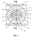
- the unlocking device 5 according to a first mode embodiment is shown in detail in FIGS. 2 and 3.
- It includes a first mechanical element that is a tube 10 secured by screwing the end of the rod 3 of the master cylinder.
- This tube is housed in a bore 17 of a second element mechanical which is a cylindrical hub 11 having a range 12 of reduced diameter.
- This litter 12 is housed in a additional hole 13 fitted on the brake pedal 1.
- the hub 11 is made integral with the pedal 1 with the aid of a elastic ring 14 which is positioned in a throat scope circular 12.
- the brake pedal 1 has a general U shape and it is made of folded sheet.
- the two mechanical elements 10 and 11 are subject to tensile and / or compression forces along an axis 9.
- the end of the tube 10 which is in the vicinity of the scope 12 has four nozzles 15 separated by slots 16.
- the slots 16 have a length chosen so as to give the beaks 15 some flexibility in flexion.
- Each spout 15 has a conical outer profile 18 which cooperates with a groove having a complementary profile 19 and arranged in the bore 17 of the hub 11.
- the four beaks 15 are all housed in the same throat conical 19.
- the spouts 15 delimit on the tube 10 a bore internal cylindrical 20 in which is positioned a first cylindrical bearing surface 22 of a piston 21.
- the piston 21 carries a pyrotechnic component 23 which lodges in a cavity of appropriate dimensions.
- the pins 24 of the component are oriented parallel to the axis 9 of the device and directed to a front face 25 of the device.
- a housing 26 is arranged in the piston 21 and allows receive connector 7 (see Figure 1) which connects to pins 24.
- the pyrotechnic component 23 is intended to generate gases that will fill a chamber 27 that extends the bore cylindrical 20. This room is delimited by a surface internal cylindrical 28 of the tube 10 and is closed by a side by the piston 21 and the other by one end of the stem 3.
- the piston 21 has a second cylindrical surface 29 of smaller diameter than the first span 22.
- This second bearing 29 is delimited on one side by a flange 30 providing a guide of the piston 21 relative to the inner cylindrical surface 28 of the chamber 27.
- the diameter of the chamber 27 is greater than that of the cylindrical bore 20 delimited by the deformable nozzles.
- the second litter 29 is intended to be positioned facing the bore 20 delimited by the spouts 15 when the piston 21 is translated by the action of the gas pressure and abuts against the surface 32. It therefore has a length greater than or equal to that of nozzles 15.
- a circular groove 31 is formed between the surface cylindrical 28 of the chamber 27 and the cylindrical bore 20 bounded by the beaks.
- This groove has a diameter chosen to prevent any interference of the beaks 15 with the flange 30 during their flexion.
- first cylindrical bearing 22 of the piston 21 has a bead 33 cooperating with a groove complementary circular arranged on the cylindrical surface of the internal bore 20 so as to ensure a positioning axial piston 21 in its holding position.
- the tube 10 and the hub 11 are integral in translation of one another through the locking means which is constituted by the jaws 15 integral with the tube 10 and cooperating with the complementary conical profile 19 arranged on the hub 11.
- This locking means is maintained in the position of locking thanks to the holding means constituted by the piston 21 whose first cylindrical bearing surface 22 prevents any bending of the beaks 15.
- the pulse received by the piston during the initiation of the component is enough to push the piston.
- the piston 21 moves until abutment of the flange 30 on the abutment surface 32. At this time the second cylindrical scope 29 of the piston 21 is located positioned opposite the bore 20 delimited by the nozzles 15.
- This second reach is less than that of the first litter 22 and it is chosen sufficiently reduced so that the deformation by radial bending of the beaks 15 is possible until clearance of their conical profile external 18 outside the supplementary dwelling 19.
- the tube 10 can then translate relative to the hub 11 direction F, which will occur when effort of a certain intensity will be applied on the pedal 1 following direction G (compressive force).
- the abutment surface 32 prevents the ejection of the piston 21 out of the device thus avoiding injury.
- Figure 4 shows a second embodiment of a connecting device according to the invention.
- This unlockable connection device 5 makes it possible to form a pyrotechnic screw 69 which will ensure a mechanical connection between two non-mechanical elements represented.
- the screw 69 comprises a head 67 and a part Threaded 68 or screw rod.
- the device unlockable link 5 will allow to separate a first mechanical element that will include the threaded rod 68 and a second mechanical element constituted by the head 67.
- the first element Mechanical 68 carries four deformable nozzles 15 regularly angularly distributed and separated by slots 16 which may be filled with grease for improve gas tightness.
- Each spout 15 has an external conical profile 18 which cooperates with a complementary profile 19 arranged in a body 70 of the head 67.
- the four nozzles delimit an internal cylindrical bore 20 which receives a piston 21.
- the axial bore 20 extends inside the rod 68 of the screw and has an internal countersink 71 constituting an axial stop for the piston 21 when the latter was translated to come to occupy its unlocking position.
- An axial channel 72 extends the bore 20 and, when the displacement of the piston 21, to evacuate the air the bore 20.
- the piston 21 comprises a seal ring 73 arranged in a groove and cooperating with a internal cylindrical surface of the bore 20. This seal is intended to provide a seal against the gases generated by the pyrotechnic component 23.
- the pyrotechnic component 23 is disposed in a internal chamber 74 which is delimited by the body 70 of the head 67 of the screw.
- a spacer ring 79 surrounds one end of the pyrotechnic component 23 and has a first surface stop 80 cooperating with the bulge 78 of the component pyrotechnic 23 and a second abutment surface 81 on which rests on one end 82 of the rod 68 of the screw.
- the screwing of the stopper 75 also makes it possible to exert, by through the ring 79, a pre-stress on the deformable nozzles 15 which are applied on the profile conical 19.
- the external profile of the body 70 of the head is here a hexagonal profile but any other profile allowing clamping using a tool would be feasible (square, cylindrical with notches for a wrench ).
- the piston is first positioned in the bore 20 of the screw rod 68 and in its locking position of the beaks 15.
- the rod 68 of the screw is then introduced into the body 70 of the head.
- the diameter of the hole through the head 70 is of course greater than that of the rod 68 of the screw.
- the nozzles 15 are therefore in abutment against the internal profile conical 19 of the body 70 of the head.
- the body 70 is screwed onto the stopper 75 carrying the pyrotechnic component 23 and the spacer ring 79.
- the depth of the bore 20 is sufficient so that, in this unlocked position, the piston 21 is more in front of the deformable nozzles 15.
- the rod 68 of the screw then separates from the head 67 of the screw. Separation is facilitated by prestressing initial given by the tightening of the cap 75 during assembly of the device.
- Such a releasable connection device can be used in all applications as simply as a normal screw. It ensures a separation as a result of a tensile force exerted between the rod and the head of the screw. For example, it is possible to use such a screw or such device for connecting a watertight load to an aircraft.
Landscapes
- Engineering & Computer Science (AREA)
- Physics & Mathematics (AREA)
- General Physics & Mathematics (AREA)
- Automation & Control Theory (AREA)
- Transportation (AREA)
- Mechanical Engineering (AREA)
- General Engineering & Computer Science (AREA)
- Actuator (AREA)
- Air Bags (AREA)
- Snaps, Bayonet Connections, Set Pins, And Snap Rings (AREA)
- Hydraulic Clutches, Magnetic Clutches, Fluid Clutches, And Fluid Joints (AREA)
- Pressure Welding/Diffusion-Bonding (AREA)
- Materials For Medical Uses (AREA)
- Safety Valves (AREA)
- Clamps And Clips (AREA)
- Lock And Its Accessories (AREA)
- Automotive Seat Belt Assembly (AREA)
Description
- la figure 1 représente schématiquement l'intégration d'un dispositif de liaison déverrouillable selon un mode de réalisation de l'invention pour réaliser la liaison d'une pédale de frein de véhicule automobile et d'une tige de maítre cylindre,
- la figure 2 représente en coupe longitudinale un premier mode de réalisation d'un dispositif de liaison selon l'invention, coupe réalisée suivant le plan dont la trace BB est repérée à la figure 3,
- la figure 3 est une coupe transversale de ce dispositif, coupe réalisée suivant le plan dont la trace AA est repérée sur la figure 2,
- la figure 4 représente en coupe longitudinale un deuxième mode de réalisation d'un dispositif de liaison déverrouillable, coupe réalisée suivant le plan dont la trace EE est repérée à la figure 5, et
- la figure 5 est une vue de la précédente en coupe transversale suivant le plan dont la trace CC est représentée sur la figure 4.
- la profondeur des rainures 16, des rainures profondes donnant une souplesse supérieure,
- l'angle des profils coniques 18 et 19, un accroissement de l'angle du cône augmentant l'effort de dégagement,
- la largeur de la gorge conique 19, une gorge large imposera pour obtenir le dégagement des becs une flexion supérieure donc un effort également supérieur,
- la largeur de chaque bec et le nombre de becs, des becs étroits pouvant fléchir avec un effort moindre .
Claims (16)
- Dispositif (5) de liaison mécanique déverrouillable pyrotechniquement entre deux éléments mécaniques susceptibles d'être soumis à des efforts de traction et/ou de compression suivant un axe, dispositif comprenant au moins un composant pyrotechnique (23) et au moins un moyen de verrouillage (15), assurant la liaison entre les deux éléments mécaniques suivant au moins un axe, moyen de verrouillage susceptible d'être libéré lorsque les éléments mécaniques sont soumis aux efforts de traction et/ou de compression suivant ledit axe et qui est maintenu dans sa position de verrouillage par des moyens de maintien (21) qui sont libérés par la pression des gaz engendrés par l'initiation du composant pyrotechnique (23), dispositif caractérisé en ce que les moyens de maintien comprennent un piston (21) pouvant coulisser dans un alésage cylindrique axial interne (20) sous l'effet de la pression des gaz engendrés par l'initiation du composant pyrotechnique (23), le moyen de verrouillage (15) étant en contact avec le piston (21) au niveau d'une surface cylindrique externe (22) ou première portée de celui-ci qui assure leur maintien en position de verrouillage, le moyen de verrouillage (15) est lié en translation avec un premier (10, 68) des éléments mécaniques et comprend au moins un profil (18) coopérant avec un profil complémentaire (19) solidaire d'un deuxième (11, 67) des éléments mécaniques, le moyen de verrouillage (15) délimitant également au moins partiellement l'alésage cylindrique axial interne (20) dans lequel peut coulisser le piston (21), le moyen de verrouillage comprend au moins deux,becs déformables (15) solidaires du premier (10, 68) des éléments mécaniques et comprenant chacun au moins un profil externe (18) coopérant avec un profil complémentaire (19) solidaire du deuxième (11, 67) des éléments mécaniques, becs délimitant l'alésage cylindrique axial interne recevant le piston (21).
- Dispositif de liaison mécanique déverrouillable selon la revendication 1, caractérisé en ce que les becs (15) ont un profil externe (18) conique.
- Dispositif de liaison mécanique déverrouillable selon la revendication 1 ou 2, caractérisé en ce que le composant pyrotechnique (23) est solidaire du piston (21).
- Dispositif de liaison mécanique déverrouillable selon la revendication 3, caractérisé en ce que l'alésage cylindrique axial interne (20) délimité par les becs (15) est prolongé par une chambre (27) destinée à recevoir la pression des gaz engendrés par l'initiation du composant pyrotechnique (23).
- Dispositif de liaison mécanique déverrouillable selon la revendication 4, caractérisé en ce que le piston (21) comporte une deuxième portée cylindrique (29) de diamètre inférieur à celui de la surface cylindrique externe (22) ou première portée maintenant les becs, deuxième portée qui vient se positionner en regard de l'alésage cylindrique axial interne (20) délimité par les becs (15) lorsque le piston (21) se translate par l'action de la pression des gaz, autorisant ainsi une flexion des becs (15) en direction du piston (21), flexion qui permet le dégagement du profil externe (18) des becs (15) d'avec son profil complémentaire (19).
- Dispositif de liaison mécanique déverrouillable selon la revendication 5, caractérisé en ce que la deuxième portée cylindrique (29) est délimitée d'un côté par une collerette (30) assurant un guidage du piston (21) par rapport à une surface cylindrique interne (28) de la chambre (27).
- Dispositif de liaison mécanique déverrouillable selon la revendication 6, caractérisé en ce que, après translation du piston (21), la collerette (30) vient se loger dans une gorge (31) aménagée à une extrémité de la chambre (27).
- Dispositif de liaison mécanique déverrouillable selon l'une quelconque des revendications 1 à 7, caractérisé en ce que la surface cylindrique externe (22) ou première portée du piston maintenant les becs comporte un bourrelet (33) coopérant avec une rainure circulaire aménagée sur la surface cylindrique de l'alésage axial interne (20) de façon à assurer un positionnement axial du piston (21) dans sa position de maintien.
- Dispositif de liaison mécanique déverrouillable selon l'une quelconque des revendications 1 à 8, caractérisé en ce qu'il comporte au moins trois becs (15) déformables régulièrement répartis angulairement.
- Dispositif de liaison mécanique déverrouillable selon la revendication 1 ou 2, caractérisé en ce que le premier des éléments mécaniques portant les becs déformables (15) comprend une partie filetée (68) constituant une tige de vis, le deuxième des éléments mécaniques constituant une tête (67) pour ladite vis.
- Dispositif de liaison mécanique déverrouillable selon la revendication 10, caractérisé en ce que le composant pyrotechnique (23) est solidaire de la tête (67) de la vis.
- Dispositif de liaison mécanique déverrouillable selon la revendication 10 ou 11, caractérisé en ce que l'alésage cylindrique axial interne (20) recevant le piston (21) est aménagé dans la tige (68) de la vis.
- Dispositif de liaison mécanique déverrouillable selon la revendication 12, caractérisé en ce que l'alésage cylindrique axial interne (20) présente un lamage interne (71) constituant une butée axiale pour le piston (21) lorsqu'il occupe sa position de déverrouillage.
- Dispositif de liaison mécanique déverrouillable selon la revendication 12 ou 13, caractérisé en ce que le piston (21) comporte un joint d'étanchéité annulaire (73) coopérant avec une surface cylindrique interne de l'alésage (20).
- Dispositif de liaison mécanique déverrouillable selon l'une quelconque des revendications 11 à 14, caractérisé en ce que la tête (67) de la vis comprend un corps (70) délimitant une chambre interne (74) qui est obturée d'un côté par la tige (68) de la vis et de l'autre par un bouchon (75) qui vient en appui sur un renflement périphérique (78) du composant pyrotechnique (23), une bague entretoise (79) entourant une extrémité du composant pyrotechnique (23) et comportant une première surface de butée (80) coopérant avec le renflement (78) du composant et une deuxième surface de butée (81) pour une extrémité (82) de la tige (68) de la vis de façon à éviter tout contact de cette dernière avec le composant pyrotechnique (23) lors du montage du bouchon (75).
- Dispositif de liaison mécanique déverrouillable selon l'une quelconque des revendications 1 à 9, caractérisé en ce que le premier élément mécanique est solidaire d'une extrémité d'une tige d'un maítre cylindre de frein de véhicule et en ce que le deuxième élément mécanique est solidaire d'une pédale de freinage.
Applications Claiming Priority (3)
| Application Number | Priority Date | Filing Date | Title |
|---|---|---|---|
| FR9815637A FR2787149B1 (fr) | 1998-12-09 | 1998-12-09 | Dispositif de deverrouillage pyrotechnique |
| FR9815637 | 1998-12-09 | ||
| PCT/FR1999/003066 WO2000034093A1 (fr) | 1998-12-09 | 1999-12-09 | Dispositif de liaison mecanique deverrouillable pyrotechniquement et mettant en oeuvre un piston |
Publications (2)
| Publication Number | Publication Date |
|---|---|
| EP1137559A1 EP1137559A1 (fr) | 2001-10-04 |
| EP1137559B1 true EP1137559B1 (fr) | 2005-09-14 |
Family
ID=9533850
Family Applications (2)
| Application Number | Title | Priority Date | Filing Date |
|---|---|---|---|
| EP99957376A Expired - Lifetime EP1137560B1 (fr) | 1998-12-09 | 1999-12-09 | Dispositif de liaison mecanique deverrouillable pyrotechniquement |
| EP99957375A Expired - Lifetime EP1137559B1 (fr) | 1998-12-09 | 1999-12-09 | Dispositif de liaison mecanique deverrouillable pyrotechniquement et mettant en oeuvre un piston |
Family Applications Before (1)
| Application Number | Title | Priority Date | Filing Date |
|---|---|---|---|
| EP99957376A Expired - Lifetime EP1137560B1 (fr) | 1998-12-09 | 1999-12-09 | Dispositif de liaison mecanique deverrouillable pyrotechniquement |
Country Status (7)
| Country | Link |
|---|---|
| US (1) | US6662702B1 (fr) |
| EP (2) | EP1137560B1 (fr) |
| AT (2) | ATE304469T1 (fr) |
| DE (2) | DE69927287D1 (fr) |
| ES (1) | ES2196882T3 (fr) |
| FR (1) | FR2787149B1 (fr) |
| WO (2) | WO2000034094A1 (fr) |
Cited By (1)
| Publication number | Priority date | Publication date | Assignee | Title |
|---|---|---|---|---|
| DE102011082150A1 (de) * | 2011-09-06 | 2013-03-07 | Zf Friedrichshafen Ag | Pedalanordnung mit Sicherheitseinrichtung |
Families Citing this family (21)
| Publication number | Priority date | Publication date | Assignee | Title |
|---|---|---|---|---|
| US6851373B2 (en) * | 2002-02-22 | 2005-02-08 | Automotive Systems Laboratory, Inc. | Airbelt inflator |
| DE10303377A1 (de) * | 2003-01-29 | 2004-08-05 | Dynamit Nobel Ais Gmbh Automotive Ignition Systems | Pyromechanisches Trennelement |
| AT6827U1 (de) * | 2003-04-23 | 2004-04-26 | Hirtenberger Automotive Safety | Trennschraube |
| US7127994B2 (en) * | 2003-10-24 | 2006-10-31 | The Boeing Company | Low shock separation joint |
| DE102004062079B4 (de) * | 2004-12-23 | 2012-03-15 | Audi Ag | Trennelement |
| DE102006022905B4 (de) * | 2004-12-23 | 2020-12-17 | Audi Ag | Trennschraube |
| DE102005017868A1 (de) * | 2005-04-19 | 2006-10-26 | Hirschmann Automotive Gmbh | Pyrotechnische Einheit für ein Sicherheitssystem, insbesondere eines Airbags oder eines Gurtstraffers eines Fahrzeugs |
| US7114427B1 (en) | 2005-10-19 | 2006-10-03 | Special Devices, Inc. | Quick-loosening mechanical linking device |
| KR100661749B1 (ko) * | 2006-02-15 | 2006-12-27 | 국방과학연구소 | 물체 결합-분리 장치 |
| EP2002198B1 (fr) * | 2006-03-30 | 2013-04-24 | Raytheon Company | Procédés et appareil pour mécanisme intégré verrouillé de poussée |
| DE102007014403B4 (de) * | 2007-03-26 | 2020-02-13 | Trw Airbag Systems Gmbh | Pyrotechnische Antriebseinheit sowie Verfahren zur Herstellung einer solchen Antriebseinheit |
| EP2292475B2 (fr) * | 2008-01-08 | 2016-08-31 | GM Global Technology Operations LLC | Système de pédale de sécurité |
| US8171839B2 (en) * | 2010-02-14 | 2012-05-08 | Brandon Terry | Reusable explosive bolt |
| DE102012107580C5 (de) * | 2012-08-17 | 2019-10-10 | Krauss-Maffei Wegmann Gmbh & Co. Kg | Vorrichtung und Verfahren zum Koppeln von einem Anbaugerät an einem Fahrzeug |
| US9482256B2 (en) * | 2012-12-21 | 2016-11-01 | Oakland University | Mechanism for rapid de-coupling of load bearing structures |
| DE102013100825B3 (de) * | 2013-01-28 | 2013-12-19 | Benteler Automobiltechnik Gmbh | Pyro-mechanischer Aktuator und Verbindungsvorrichtung mit einem solchen Aktuator |
| CN104590563B (zh) * | 2013-10-31 | 2016-12-07 | 北京航天长征飞行器研究所 | 一种多功能自控连接抛撒装置 |
| GB2537414B (en) * | 2015-04-17 | 2019-11-13 | Graviner Ltd Kidde | Pyrotechnic valve |
| US20160356586A1 (en) * | 2015-06-02 | 2016-12-08 | Fast Brass, Llc | Shell retaining assembly |
| CN105000185B (zh) * | 2015-08-13 | 2017-03-08 | 中国航空工业集团公司西安飞机设计研究所 | 一种货台牵引转换机构 |
| US11713142B2 (en) * | 2017-12-01 | 2023-08-01 | Ensign-Bickford Aerospace & Defense Comany | Separation device assemblies |
Family Cites Families (27)
| Publication number | Priority date | Publication date | Assignee | Title |
|---|---|---|---|---|
| US3147663A (en) * | 1961-09-14 | 1964-09-08 | Hi Shear Corp | Explosive nut retainer |
| US3265408A (en) * | 1961-11-06 | 1966-08-09 | Hi Shear Corp | Explosively separable coupling |
| US3196745A (en) * | 1963-06-07 | 1965-07-27 | Martin Marietta Corp | Separation and pin puller mechanism |
| US3262351A (en) * | 1964-03-20 | 1966-07-26 | James E Webb | Separation nut |
| US3405593A (en) * | 1966-04-18 | 1968-10-15 | Aerospace Systems Company | Separation device |
| US3754496A (en) * | 1971-08-20 | 1973-08-28 | Us Navy | Explosive bolt |
| US3881394A (en) * | 1971-09-15 | 1975-05-06 | Ato Inc | Gas generator assembly |
| US3813984A (en) * | 1972-07-12 | 1974-06-04 | Hi Shear Corp | Separation nut |
| US3926090A (en) * | 1973-03-23 | 1975-12-16 | Hi Shear Corp | Separation nut |
| US3910154A (en) * | 1973-05-02 | 1975-10-07 | Hi Shear Corp | Separation nut |
| US4002120A (en) * | 1975-07-31 | 1977-01-11 | The United States Of America As Represented By The Secretary Of The Navy | Missile stage coupler |
| US4064783A (en) * | 1977-01-27 | 1977-12-27 | The United States Of America As Represented By The Secretary Of The Navy | Pressure-balanced underwater structural release system |
| US4158322A (en) * | 1977-08-22 | 1979-06-19 | The United States Of America As Represented By The Secretary Of The Navy | Pyrotechnic separation device |
| US4187759A (en) * | 1977-09-16 | 1980-02-12 | The United States Of America As Represented By The Secretary Of The Navy | Separation nut system |
| US4314500A (en) * | 1980-01-25 | 1982-02-09 | The United States Of America As Represented By The Secretary Of The Air Force | Instantaneous opening positive lock mechanism |
| DE3819813A1 (de) * | 1988-06-10 | 1989-12-14 | Hilti Ag | Pulverkraftbetriebenes setzgeraet |
| FR2637252B1 (fr) * | 1988-10-05 | 1990-12-28 | Aerospatiale | Dispositif de solidarisation/desolidarisation provisoire de deux elements l'un a l'autre, et de separation ulterieure |
| US5221171A (en) * | 1992-10-15 | 1993-06-22 | G & H Technology, Inc. | Non-explosive separation nut |
| DE4305049C2 (de) * | 1993-02-18 | 1996-09-19 | Hs Tech & Design | Vorrichtung zum Zurückziehen von Bauteilen in einem Kraftfahrzeug aus einer Normalposition in eine Sicherheitsposition |
| US5282709A (en) * | 1993-05-04 | 1994-02-01 | G & H Technology, Inc. | Separation nut with a restraining wire |
| DE19515852C2 (de) * | 1994-05-21 | 2001-11-08 | Volkswagen Ag | Betätigungsanordnung für ein Kraftfahrzeug |
| FR2736615B1 (fr) * | 1995-07-13 | 1997-09-19 | Aerospatiale | Deverouilleur a ecrou fendu pour microsatellite, a redondance mecanique et pyrotechnique complete |
| DE19634257A1 (de) * | 1995-08-30 | 1997-03-06 | Volkswagen Ag | Bremsanlage für ein Fahrzeug |
| DE19617372C1 (de) * | 1996-04-30 | 1998-01-02 | Lucas Ind Plc | Pedalanordnung für ein Kraftfahrzeug |
| US5695306A (en) * | 1996-05-08 | 1997-12-09 | Lockheed Martin Corp. | Fusible member connection apparatus and method |
| US5868538A (en) * | 1996-09-30 | 1999-02-09 | R-Tex, Llc | Quick-release lock assembly |
| GB2322836A (en) * | 1997-02-25 | 1998-09-09 | Rover Group | A vehicle braking system permitting collapse of the pedal upon collision |
-
1998
- 1998-12-09 FR FR9815637A patent/FR2787149B1/fr not_active Expired - Fee Related
-
1999
- 1999-12-09 WO PCT/FR1999/003067 patent/WO2000034094A1/fr active IP Right Grant
- 1999-12-09 WO PCT/FR1999/003066 patent/WO2000034093A1/fr active IP Right Grant
- 1999-12-09 AT AT99957375T patent/ATE304469T1/de not_active IP Right Cessation
- 1999-12-09 ES ES99957376T patent/ES2196882T3/es not_active Expired - Lifetime
- 1999-12-09 DE DE69927287T patent/DE69927287D1/de not_active Expired - Lifetime
- 1999-12-09 US US09/857,617 patent/US6662702B1/en not_active Expired - Fee Related
- 1999-12-09 DE DE69908971T patent/DE69908971T2/de not_active Expired - Fee Related
- 1999-12-09 EP EP99957376A patent/EP1137560B1/fr not_active Expired - Lifetime
- 1999-12-09 AT AT99957376T patent/ATE243126T1/de not_active IP Right Cessation
- 1999-12-09 EP EP99957375A patent/EP1137559B1/fr not_active Expired - Lifetime
Cited By (1)
| Publication number | Priority date | Publication date | Assignee | Title |
|---|---|---|---|---|
| DE102011082150A1 (de) * | 2011-09-06 | 2013-03-07 | Zf Friedrichshafen Ag | Pedalanordnung mit Sicherheitseinrichtung |
Also Published As
| Publication number | Publication date |
|---|---|
| EP1137560A1 (fr) | 2001-10-04 |
| ATE304469T1 (de) | 2005-09-15 |
| EP1137560B1 (fr) | 2003-06-18 |
| DE69908971D1 (de) | 2003-07-24 |
| ES2196882T3 (es) | 2003-12-16 |
| US6662702B1 (en) | 2003-12-16 |
| EP1137559A1 (fr) | 2001-10-04 |
| WO2000034094A8 (fr) | 2001-09-20 |
| WO2000034093A1 (fr) | 2000-06-15 |
| ATE243126T1 (de) | 2003-07-15 |
| DE69927287D1 (de) | 2005-10-20 |
| DE69908971T2 (de) | 2004-05-06 |
| FR2787149A1 (fr) | 2000-06-16 |
| WO2000034094A1 (fr) | 2000-06-15 |
| FR2787149B1 (fr) | 2001-01-05 |
Similar Documents
| Publication | Publication Date | Title |
|---|---|---|
| EP1137559B1 (fr) | Dispositif de liaison mecanique deverrouillable pyrotechniquement et mettant en oeuvre un piston | |
| EP2689110B1 (fr) | Dispositif d'obturation a verrouillage auto-activable | |
| CA2204386C (fr) | Dispositif d'obturation a verrouillage auto-activable | |
| EP0960300A1 (fr) | Dispositif de raccordement rapide d'un tube a un element rigide a bague anti-extraction et temoin d'integrite | |
| FR2661466A1 (fr) | Mecanisme de liaison a deverrouillage rapide, utilisable notamment sur des engins spatiaux. | |
| CA2345735C (fr) | Dispositif d'injection a usage unique destine a etre pre-rempli | |
| FR2683310A1 (fr) | Dispositif d'ejection d'elements de charge utile hors de l'enveloppe d'un obus cargo. | |
| EP0814274B1 (fr) | Dispositif pour la fixation de l'articulation d'un cylindre émetteur sur une pédale d'embrayage d'un véhicule automobile | |
| EP1610086A1 (fr) | Conteneur pour munition | |
| EP1162333B1 (fr) | Verrou pyrotechnique comprenant un moyen de maintien axial de sa tige | |
| EP3617543B1 (fr) | Disque arriere d'une pile de disques en carbone de frein d'aeronef equipe de plots, et frein faisant application | |
| EP0235028A1 (fr) | Allumeur fixable dans la tuyère d'un propulseur | |
| EP1080001B1 (fr) | Dispositif de commande d'un organe d'un vehicule automobile au moyen d'une pedale | |
| EP1683709B1 (fr) | Élément de liaison entre un berceau et un élément d'absorption de choc | |
| WO1996000669A1 (fr) | Ensemble d'un servomoteur pneumatique d'assistance au freinage et d'un maitre-cylindre | |
| EP1079994B1 (fr) | Dispositif de fragilisation d'un axe de pivotement d'une pedale automobile | |
| FR2493939A1 (fr) | Frein a disque | |
| FR2824875A1 (fr) | Actionneur pyrotechnique muni d'une rondelle de retenue | |
| WO2014206830A2 (fr) | Servofrein électromécanique | |
| EP0939715B1 (fr) | Systeme de feinage assiste a reaction hydraulique amelioree | |
| WO2020187659A1 (fr) | Dispositif pyrotechnique de libération d'écrou | |
| EP0115223B1 (fr) | Maître-cylindre comportant un organe de réaction annulaire | |
| FR2771458A1 (fr) | Dispositif de fixation d'un organe sur un arbre | |
| EP2616312B1 (fr) | Dispositif de couplage en rotation de deux organes, par déformation de moyens de couplage | |
| FR2825057A1 (fr) | Servomoteur d'assistance pneumatique au freinage a hauteur de saut variable |
Legal Events
| Date | Code | Title | Description |
|---|---|---|---|
| PUAI | Public reference made under article 153(3) epc to a published international application that has entered the european phase |
Free format text: ORIGINAL CODE: 0009012 |
|
| 17P | Request for examination filed |
Effective date: 20010508 |
|
| AK | Designated contracting states |
Kind code of ref document: A1 Designated state(s): AT BE CH CY DE DK ES FI FR GB GR IE IT LI LU MC NL PT SE |
|
| 17Q | First examination report despatched |
Effective date: 20021112 |
|
| GRAP | Despatch of communication of intention to grant a patent |
Free format text: ORIGINAL CODE: EPIDOSNIGR1 |
|
| GRAS | Grant fee paid |
Free format text: ORIGINAL CODE: EPIDOSNIGR3 |
|
| GRAA | (expected) grant |
Free format text: ORIGINAL CODE: 0009210 |
|
| AK | Designated contracting states |
Kind code of ref document: B1 Designated state(s): AT BE CH CY DE DK ES FI FR GB GR IE IT LI LU MC NL PT SE |
|
| PG25 | Lapsed in a contracting state [announced via postgrant information from national office to epo] |
Ref country code: NL Free format text: LAPSE BECAUSE OF FAILURE TO SUBMIT A TRANSLATION OF THE DESCRIPTION OR TO PAY THE FEE WITHIN THE PRESCRIBED TIME-LIMIT Effective date: 20050914 Ref country code: IT Free format text: LAPSE BECAUSE OF FAILURE TO SUBMIT A TRANSLATION OF THE DESCRIPTION OR TO PAY THE FEE WITHIN THE PRE;WARNING: LAPSES OF ITALIAN PATENTS WITH EFFECTIVE DATE BEFORE 2007 MAY HAVE OCCURRED AT ANY TIME BEFORE 2007. THE CORRECT EFFECTIVE DATE MAY BE DIFFERENT FROM THE ONE RECORDED.SCRIBED TIME-LIMIT Effective date: 20050914 Ref country code: IE Free format text: LAPSE BECAUSE OF FAILURE TO SUBMIT A TRANSLATION OF THE DESCRIPTION OR TO PAY THE FEE WITHIN THE PRESCRIBED TIME-LIMIT Effective date: 20050914 Ref country code: GB Free format text: LAPSE BECAUSE OF FAILURE TO SUBMIT A TRANSLATION OF THE DESCRIPTION OR TO PAY THE FEE WITHIN THE PRESCRIBED TIME-LIMIT Effective date: 20050914 Ref country code: FI Free format text: LAPSE BECAUSE OF FAILURE TO SUBMIT A TRANSLATION OF THE DESCRIPTION OR TO PAY THE FEE WITHIN THE PRESCRIBED TIME-LIMIT Effective date: 20050914 Ref country code: AT Free format text: LAPSE BECAUSE OF FAILURE TO SUBMIT A TRANSLATION OF THE DESCRIPTION OR TO PAY THE FEE WITHIN THE PRESCRIBED TIME-LIMIT Effective date: 20050914 |
|
| REG | Reference to a national code |
Ref country code: GB Ref legal event code: FG4D Free format text: NOT ENGLISH |
|
| REG | Reference to a national code |
Ref country code: CH Ref legal event code: EP |
|
| REG | Reference to a national code |
Ref country code: IE Ref legal event code: FG4D Free format text: LANGUAGE OF EP DOCUMENT: FRENCH |
|
| REF | Corresponds to: |
Ref document number: 69927287 Country of ref document: DE Date of ref document: 20051020 Kind code of ref document: P |
|
| PG25 | Lapsed in a contracting state [announced via postgrant information from national office to epo] |
Ref country code: CY Free format text: LAPSE BECAUSE OF FAILURE TO SUBMIT A TRANSLATION OF THE DESCRIPTION OR TO PAY THE FEE WITHIN THE PRESCRIBED TIME-LIMIT Effective date: 20051209 |
|
| PG25 | Lapsed in a contracting state [announced via postgrant information from national office to epo] |
Ref country code: SE Free format text: LAPSE BECAUSE OF FAILURE TO SUBMIT A TRANSLATION OF THE DESCRIPTION OR TO PAY THE FEE WITHIN THE PRESCRIBED TIME-LIMIT Effective date: 20051214 Ref country code: GR Free format text: LAPSE BECAUSE OF FAILURE TO SUBMIT A TRANSLATION OF THE DESCRIPTION OR TO PAY THE FEE WITHIN THE PRESCRIBED TIME-LIMIT Effective date: 20051214 Ref country code: DK Free format text: LAPSE BECAUSE OF FAILURE TO SUBMIT A TRANSLATION OF THE DESCRIPTION OR TO PAY THE FEE WITHIN THE PRESCRIBED TIME-LIMIT Effective date: 20051214 |
|
| PG25 | Lapsed in a contracting state [announced via postgrant information from national office to epo] |
Ref country code: DE Free format text: LAPSE BECAUSE OF FAILURE TO SUBMIT A TRANSLATION OF THE DESCRIPTION OR TO PAY THE FEE WITHIN THE PRESCRIBED TIME-LIMIT Effective date: 20051215 |
|
| PG25 | Lapsed in a contracting state [announced via postgrant information from national office to epo] |
Ref country code: ES Free format text: LAPSE BECAUSE OF FAILURE TO SUBMIT A TRANSLATION OF THE DESCRIPTION OR TO PAY THE FEE WITHIN THE PRESCRIBED TIME-LIMIT Effective date: 20051225 |
|
| PG25 | Lapsed in a contracting state [announced via postgrant information from national office to epo] |
Ref country code: MC Free format text: LAPSE BECAUSE OF NON-PAYMENT OF DUE FEES Effective date: 20051231 Ref country code: LU Free format text: LAPSE BECAUSE OF NON-PAYMENT OF DUE FEES Effective date: 20051231 Ref country code: LI Free format text: LAPSE BECAUSE OF NON-PAYMENT OF DUE FEES Effective date: 20051231 Ref country code: CH Free format text: LAPSE BECAUSE OF NON-PAYMENT OF DUE FEES Effective date: 20051231 Ref country code: BE Free format text: LAPSE BECAUSE OF NON-PAYMENT OF DUE FEES Effective date: 20051231 |
|
| PG25 | Lapsed in a contracting state [announced via postgrant information from national office to epo] |
Ref country code: PT Free format text: LAPSE BECAUSE OF FAILURE TO SUBMIT A TRANSLATION OF THE DESCRIPTION OR TO PAY THE FEE WITHIN THE PRESCRIBED TIME-LIMIT Effective date: 20060214 |
|
| NLV1 | Nl: lapsed or annulled due to failure to fulfill the requirements of art. 29p and 29m of the patents act | ||
| GBV | Gb: ep patent (uk) treated as always having been void in accordance with gb section 77(7)/1977 [no translation filed] |
Effective date: 20050914 |
|
| REG | Reference to a national code |
Ref country code: IE Ref legal event code: FD4D |
|
| PLBE | No opposition filed within time limit |
Free format text: ORIGINAL CODE: 0009261 |
|
| STAA | Information on the status of an ep patent application or granted ep patent |
Free format text: STATUS: NO OPPOSITION FILED WITHIN TIME LIMIT |
|
| REG | Reference to a national code |
Ref country code: CH Ref legal event code: PL |
|
| 26N | No opposition filed |
Effective date: 20060615 |
|
| BERE | Be: lapsed |
Owner name: GIAT INDUSTRIES Effective date: 20051231 |
|
| PGFP | Annual fee paid to national office [announced via postgrant information from national office to epo] |
Ref country code: FR Payment date: 20141217 Year of fee payment: 16 |
|
| REG | Reference to a national code |
Ref country code: FR Ref legal event code: ST Effective date: 20160831 |
|
| PG25 | Lapsed in a contracting state [announced via postgrant information from national office to epo] |
Ref country code: FR Free format text: LAPSE BECAUSE OF NON-PAYMENT OF DUE FEES Effective date: 20151231 |