EP1137335A2 - Fertigungsstrasse zur Montage elektronischer Bauteile - Google Patents
Fertigungsstrasse zur Montage elektronischer Bauteile Download PDFInfo
- Publication number
- EP1137335A2 EP1137335A2 EP01106821A EP01106821A EP1137335A2 EP 1137335 A2 EP1137335 A2 EP 1137335A2 EP 01106821 A EP01106821 A EP 01106821A EP 01106821 A EP01106821 A EP 01106821A EP 1137335 A2 EP1137335 A2 EP 1137335A2
- Authority
- EP
- European Patent Office
- Prior art keywords
- mounting apparatus
- mounting
- component
- alternate
- electronic component
- Prior art date
- Legal status (The legal status is an assumption and is not a legal conclusion. Google has not performed a legal analysis and makes no representation as to the accuracy of the status listed.)
- Granted
Links
Images


Classifications
-
- H—ELECTRICITY
- H05—ELECTRIC TECHNIQUES NOT OTHERWISE PROVIDED FOR
- H05K—PRINTED CIRCUITS; CASINGS OR CONSTRUCTIONAL DETAILS OF ELECTRIC APPARATUS; MANUFACTURE OF ASSEMBLAGES OF ELECTRICAL COMPONENTS
- H05K13/00—Apparatus or processes specially adapted for manufacturing or adjusting assemblages of electric components
- H05K13/08—Monitoring manufacture of assemblages
- H05K13/085—Production planning, e.g. of allocation of products to machines, of mounting sequences at machine or facility level
-
- H—ELECTRICITY
- H05—ELECTRIC TECHNIQUES NOT OTHERWISE PROVIDED FOR
- H05K—PRINTED CIRCUITS; CASINGS OR CONSTRUCTIONAL DETAILS OF ELECTRIC APPARATUS; MANUFACTURE OF ASSEMBLAGES OF ELECTRICAL COMPONENTS
- H05K13/00—Apparatus or processes specially adapted for manufacturing or adjusting assemblages of electric components
- H05K13/04—Mounting of components, e.g. of leadless components
- H05K13/0417—Feeding with belts or tapes
-
- Y—GENERAL TAGGING OF NEW TECHNOLOGICAL DEVELOPMENTS; GENERAL TAGGING OF CROSS-SECTIONAL TECHNOLOGIES SPANNING OVER SEVERAL SECTIONS OF THE IPC; TECHNICAL SUBJECTS COVERED BY FORMER USPC CROSS-REFERENCE ART COLLECTIONS [XRACs] AND DIGESTS
- Y10—TECHNICAL SUBJECTS COVERED BY FORMER USPC
- Y10T—TECHNICAL SUBJECTS COVERED BY FORMER US CLASSIFICATION
- Y10T29/00—Metal working
- Y10T29/49—Method of mechanical manufacture
- Y10T29/49002—Electrical device making
- Y10T29/49117—Conductor or circuit manufacturing
- Y10T29/49124—On flat or curved insulated base, e.g., printed circuit, etc.
- Y10T29/4913—Assembling to base an electrical component, e.g., capacitor, etc.
-
- Y—GENERAL TAGGING OF NEW TECHNOLOGICAL DEVELOPMENTS; GENERAL TAGGING OF CROSS-SECTIONAL TECHNOLOGIES SPANNING OVER SEVERAL SECTIONS OF THE IPC; TECHNICAL SUBJECTS COVERED BY FORMER USPC CROSS-REFERENCE ART COLLECTIONS [XRACs] AND DIGESTS
- Y10—TECHNICAL SUBJECTS COVERED BY FORMER USPC
- Y10T—TECHNICAL SUBJECTS COVERED BY FORMER US CLASSIFICATION
- Y10T29/00—Metal working
- Y10T29/53—Means to assemble or disassemble
- Y10T29/53039—Means to assemble or disassemble with control means energized in response to activator stimulated by condition sensor
- Y10T29/53048—Multiple station assembly or disassembly apparatus
- Y10T29/53052—Multiple station assembly or disassembly apparatus including position sensor
-
- Y—GENERAL TAGGING OF NEW TECHNOLOGICAL DEVELOPMENTS; GENERAL TAGGING OF CROSS-SECTIONAL TECHNOLOGIES SPANNING OVER SEVERAL SECTIONS OF THE IPC; TECHNICAL SUBJECTS COVERED BY FORMER USPC CROSS-REFERENCE ART COLLECTIONS [XRACs] AND DIGESTS
- Y10—TECHNICAL SUBJECTS COVERED BY FORMER USPC
- Y10T—TECHNICAL SUBJECTS COVERED BY FORMER US CLASSIFICATION
- Y10T29/00—Metal working
- Y10T29/53—Means to assemble or disassemble
- Y10T29/5313—Means to assemble electrical device
- Y10T29/53174—Means to fasten electrical component to wiring board, base, or substrate
- Y10T29/53183—Multilead component
-
- Y—GENERAL TAGGING OF NEW TECHNOLOGICAL DEVELOPMENTS; GENERAL TAGGING OF CROSS-SECTIONAL TECHNOLOGIES SPANNING OVER SEVERAL SECTIONS OF THE IPC; TECHNICAL SUBJECTS COVERED BY FORMER USPC CROSS-REFERENCE ART COLLECTIONS [XRACs] AND DIGESTS
- Y10—TECHNICAL SUBJECTS COVERED BY FORMER USPC
- Y10T—TECHNICAL SUBJECTS COVERED BY FORMER US CLASSIFICATION
- Y10T29/00—Metal working
- Y10T29/53—Means to assemble or disassemble
- Y10T29/5313—Means to assemble electrical device
- Y10T29/53187—Multiple station assembly apparatus
-
- Y—GENERAL TAGGING OF NEW TECHNOLOGICAL DEVELOPMENTS; GENERAL TAGGING OF CROSS-SECTIONAL TECHNOLOGIES SPANNING OVER SEVERAL SECTIONS OF THE IPC; TECHNICAL SUBJECTS COVERED BY FORMER USPC CROSS-REFERENCE ART COLLECTIONS [XRACs] AND DIGESTS
- Y10—TECHNICAL SUBJECTS COVERED BY FORMER USPC
- Y10T—TECHNICAL SUBJECTS COVERED BY FORMER US CLASSIFICATION
- Y10T29/00—Metal working
- Y10T29/53—Means to assemble or disassemble
- Y10T29/5313—Means to assemble electrical device
- Y10T29/53191—Means to apply vacuum directly to position or hold work part
Definitions
- the present invention relates to an apparatus and a method for mounting electronic components utilizing a plurality of mounting apparatus of electronic components, which have a plurality of component feeding units, and a component mounting unit for receiving electronic components from the feeding units and for mounting electronic components on a print circuit board.
- the present invention involves a production line for mounting electronic components having a plurality of mounting apparatus in which a mounting apparatus assumes a responsibility of another mounting apparatus for improving the overall production efficiency of the production line when the latter mounting apparatus has a longer cycle time than originally planned due to a higher malfunction rate of one of its component feeding units for supplying an electronic component, and when the former mounting apparatus can mount the same electronic component which is planned to be mounted by the latter mounting apparatus.
- an apparatus as well as a method utilizing a plurality of mounting apparatus of electronic components, which have a plurality of component feeding units, and a component mounting unit for receiving electronic components from the feeding units and for mounting electronic components on a print circuit board.
- the apparatus has a memory means for recording a malfunction rate for each of its feeding units, and a computation means for comparing the malfunction rate to a predetermined value at a predetermined time for evaluating the malfunction rate.
- a selection means of the apparatus tries to choose an alternate component feeding unit on a different mounting apparatus, which supplies the same electronic component as the unit having a higher malfunction rate than the predetermined value.
- a control means of the apparatus has the alternate component feeding unit supplying the electronic component for mounting on the print circuit board, and has the component feeding unit with the malfunction rate higher than the predetermined value discontinuing supplying the electronic component.
- the memory means records the numbers both for total and unsuccessful pick-up procedures for each of the component feeding units of all the mounting apparatus in the production line, and the malfunction rate is calculated from the two numbers at a predetermined time for evaluating the malfunction rates.
- the configuration described above is able to prevent, utilizing the alternation scheme, the production line for mounting electronic components from having a lower production efficiency than expected even when one of the mounting apparatus has a longer cycle time due to a higher malfunction rate of its component feeding unit.
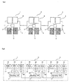
- FIG. 1 is a conceptual plan view showing a portion of a production line for mounting electronic components as an embodiment of the present invention.
- FIG. 2 is a block diagram showing a portion of a control scheme of the production line for mounting electronic components.
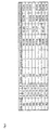
- FIG. 3 shows a portion of the master data for all the mounting procedures performed at the mounting apparatus 1, 2, and 3.
- FIG. 4 shows three sets of mounting data stored in the RAM of each of the three mounting apparatus with an all-data distribution scheme.
- FIG. 5 shows three sets of mounting data stored in the RAM of each of the three mounting apparatus with a minimal-data distribution scheme.
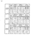
- FIG. 6 shows three sets of data on the pick-up procedures stored in the RAM of each of the three mounting apparatus.
- FIG. 7 shows a flowchart of the mounting operation of the mounting apparatus 1.
- FIG. 1 is a conceptual plan view of a production line for mounting electronic components as an embodiment of the present invention, in which three mounting apparatus 1, 2, 3 are simultaneously used.
- Each of the component feeding devices 5 and component feeding trays 6 serves as a component feeding unit.
- an incoming conveyer receives a print circuit board from an upstream process and transports the print circuit board to the portion for positioning where the print circuit board is positioned for the mounting procedures by a positioning means not shown in the figure.
- the outgoing conveyer receives the print circuit board from the portion for positioning, and transports the print circuit board to a downstream process.
- a mounting unit 7 has a plurality of suction nozzles for picking up electronic components and mounting them on the print circuit board, and is capable of moving in the X and Y directions by, for example, an X-axis motor and a Y-axis motor, respectively. Furthermore, each mounting unit 7 has a vertical motor for vertically moving the suction nozzles and a ⁇ -axis motor for rotating the suction nozzles around a vertical axis. This configuration enables the movements of the suction nozzles of the mounting unit 7 in the X and Y directions as well as the vertical direction, and the vertical rotation of the suction nozzles of the mounting unit 7.
- the base 4 Furthermore, there is on the base 4 provided a camera, not shown in the figure, for observing the position of the electronic component picked up by the suction nozzle, the shift of the suction nozzle relative to the electronic component from a proper position is estimated on the X and Y directions and the rotation based on the results of the position observation by the camera.
- the estimated shift is corrected using the X-axis, Y-axis, and ⁇ -axis motors when the electronic component held by the suction nozzle is mounted on the print circuit board.
- FIG. 2 is a block diagram showing a portion of a control scheme of the production line for mounting electronic components having the mounting apparatus 1, 2, 3.
- Three mounting apparatus 1, 2, 3 have CPU 10, 20, 30, respectively, for controlling their mounting procedures.
- Three CPU, 10, 20, 30 are connected to RAM (Random Access Memory) 12, 22, 32, and ROM (Read Only Memory) 13, 23, 33, respectively, through bus lines 11, 21, 31.
- the CPU 10, 20, 30 control the mounting procedures of the electronic components by the mounting apparatus 1, 2, 3 using data stored in the RAM 12, 22, 32 and programs stored in the ROM 13, 23, 33.
- the mounting unit 7 is controlled by the CPU 10, 20, 30 through interfaces 14, 24, 34, respectively, and the three mounting apparatus are interconnected through interfaces 15, 25, 35.
- the RAM 12 stores the master data for all the mounting procedures performed by the mounting apparatus 1, 2, 3.
- the master data includes, as shown in FIG. 3, for each step (denoted as step number in the figure) of the mounting procedures, the X and Y coordinates (shown by X and Y in the figure) of mounting position within the plane of the print circuit board, the rotation ( ⁇ ) of mounting, the location number indicating the location of a specific electronic component within a component feeding device 5 or component feeding tray 6 in a mounting apparatus, the mounting apparatus to be used, the type of the electronic component to be mounted, and the location number of the mounting apparatus which can be alternated
- the mounting apparatus 1 picks up an electronic component, RS1005, from a location denoted by a location number, 101, and mounts RS1005 on a print circuit board at a position defined by the X and Y coordinates, X1, Y1 and the rotation angle, ⁇ 1 .
- RAM 12 22, 32 store the data for the numbers of total and unsuccessful pick-up procedures and the rate of unsuccessful pick-up procedure for each of the location numbers of the mounting apparatus. After each mounting procedure, the data specific to the mounting procedure is renewed and recorded in the RAM 12, 22, 32. Unsuccessful pickups include a missing electronic component from the suction nozzle, a "standing" electronic component (the face held by the nozzle is not a correct face of the component), a leak in the vacuum for suction detected by a vacuum sensor, an incorrect component positioning detected by the observation camera, a loose lead found by the observation camera, and an incorrect component thickness detected by the observation camera.
- the rate of unsuccessful pick-up procedure is expressed in % by dividing the number of unsuccessful pick-up procedures by the number of total pick-up procedures and multiplying by 100, as shown in the figure.
- each CPU 10, 20, 30 compares such rates of its mounting apparatus to corresponding predetermined values.
- Such predetermined times for the evaluation include a time when the number of unsuccessful pick-up procedures reaches a predetermined number, a time when the number of discontinuing the mounting procedure reaches a predetermined number, and a time when the total number pick-up procedures reaches a predetermined number. If a rate of unsuccessful pick-up procedure for an electronic component is larger than the predetermined value, the CPU chooses a mounting apparatus which is capable of mounting the same electronic component as the one with the higher rate when such a mounting apparatus is available.
- the CPU changes, as described in more detail later, the master data for mounting procedures such that the alternate mounting apparatus picks up the same electronic component from the component feeding device 5 or the component feeding tray, which stores the same component, and mounts the component on the print circuit board.
- the alternate mounting apparatus can be the one in the upstream or the one in the down stream of the production line. If the mounting apparatus requesting the alternate is the one in the most upstream, the mounting apparatus 1, and the alternate mounting apparatus is the one in the middle, the mounting apparatus 2, CPU 10 asks CPU 20 for the alternate, and the electronic component needing the alternate is mounted by the mounting apparatus 2 after the print circuit board with all other components being mounted by the mounting apparatus 1 is sent to the mounting apparatus 2. Conversely, if the mounting apparatus requesting the alternate is the one in the most downstream, the mounting apparatus 3, and the alternate mounting apparatus is the one in the middle, the mounting apparatus 2, CPU 30 asks CPU 20 for the alternate, and the electronic component needing the alternate is mounted by the mounting apparatus 20 before the print circuit board is sent to the mounting apparatus 3. It is also possible that a mounting apparatus needing an alternate finds an alternate component feeding device 5, or component feeding tray 6 within itself.
- the predetermined vales to be compared with the rates of unsuccessful pick-up procedure are stored only in RAM 12. However, these values can be stored in each of three RAM 12, 22, 32. Furthermore, although the rates of unsuccessful pick-up procedure are calculated and recorded in RAM 12, 22, 32 after each mounting procedure in this embodiment, the rates are calculated from the number of total mounting procedures and the number of unsuccessful mounting procedures stored in RAM 12, 22, 32, by the corresponding CPU 10, 20, 30 only at the predetermined time for the evaluation in other embodiment.
- the three columns from the right, designated as apparatus 1, 2, and 3 in the figure, contain the data for the alternate for the component type, RS1005. If the rate of unsuccessful pick-up procedure on the component feeding device 5 denoted by the location number 101 of the mounting apparatus 1 is higher than the predetermined value, the first choice for the alternate is the component feeding device 5 denoted by the location number 201 of the mounting apparatus 1. If it is found that the component feeding device 5 denoted by the location number 201 has the rate higher than the predetermined value, next choice for the alternate is the component feeding device 5 denoted by the location number 102 of the mounting apparatus 2. Accordingly, the preferences of other choices of the alternate are determined based on the data shown in the figure.
- CPU 10 distributes subsets of the master data for mounting procedures stored in RAM 12 to the three mounting apparatus 1, 2, 3 taking the workload distribution into consideration, and has the data stored in RAM 12, 22, 32.
- the subsets of the master data can include all the data needed for the mounting procedures of the three mounting apparatus, as shown in FIG. 4, or be limited to only the portion of the data needed for the mounting procedures of one mounting apparatus, as shown in FIG. 5.
- the three mounting apparatus 1, 2, 3 start mounting procedures of the electronic components guided by the operation programs stored in ROM 13, 23, 33.
- the incoming conveyer receives a print circuit board from an upstream process and transports the print circuit board to the portion for positioning where the print circuit board is positioned for the mounting procedures by a positioning means.
- a positioning means For the sake of better understanding, the description hereinafter will be confined to the mounting procedures of the mounting apparatus 1 by referring to FIG. 4, FIG. 6 and FIG. 7.
- CPU 10 finds out if it is the time for evaluating the rate of unsuccessful pick-up procedure. If it is not the time for the evaluation, CPU 10 looks for a request for the alternate from either CPU 20, or CPU 30. Then, if there is such a request, CPU 10 looks for a possible alternate within the mounting apparatus 1. When there is not a request for the alternate, or when there is such a request but there is not any alternate available, CPU 10 carries on the mounting procedures of the mounting apparatus 1 as specified by the original master data.
- the mounting apparatus 1 picks up the electronic component, RS1005, from the component feeding device 5 denoted by the location number 101, detects the shift of the component from the proper position in the X and Y directions and the rotation around the vertical axis using the observation camera, corrects the shift using the X-axis, Y-axis, and ⁇ motors, and mounts the electronic component on the print circuit board. This mounting procedure continues until CPU receives an alternate request which can be satisfied or CPU finds out that it is the time for the evaluation.
- CPU 10 When CPU 10 receives an alternate request from CPU 20 or CPU 30 and finds an available alternate within the apparatus 1, CPU 10 carries out the following procedure to activate a step for mounting the electronic component needing the alternate.
- the column C contains the command parameters for activating each step, or mounting procedure, of the mounting apparatus.
- the parameter "S” When the parameter "S" is recorded in the column for a step, the mounting procedure corresponding to the step is not performed by the mounting apparatus 1.
- the parameter "M" is recorded in the column for a step, the mounting procedure corresponding to the step is performed by the mounting apparatus 1.
- CPU 10 now, changes the parameter of the step from "S" to "M" in the data stored in RAM 12 to activate the step.
- the mounting apparatus 1 Based on the revised data for mounting procedures, the mounting apparatus 1 performs an additional mounting procedure for mounting the electronic component needing the alternate before the print circuit board is transported downstream. This additional mounting procedure can be performed at the end of all the originally scheduled mounting procedures, or in between those mounting procedures.
- CPU 10 finds out, based on the data stored in RAM 12, that it is the predetermined time for evaluating the rate of unsuccessful pick-up procedure, CPU 10 compares the rate to the predetermined value.
- predetermined times for the evaluation include a time when the number of unsuccessful pick-up procedures reaches a predetermined number, a time when the number of discontinuing the mounting procedure reaches a predetermined number, and a time when the total number pick-up procedures reaches a predetermined number.
- the CPU 10 When the rate is not higher than the predetermined value, the CPU 10 carries on the mounting procedures based on the original data for mounting apparatus 1. When the rate is higher than the predetermined value, CPU 10 informs the operator of the event, and finds out if the mounting apparatus 2 or 3 is available as the alternate (CPU can also search the mounting apparatus 1 if it has another component feeding device 5, or tray 6 for the same component). The mounting operation resumes if there is not any alternate available. And when an alternate is available, CPU 10 changes the command parameter of the step for mounting the electronic component needing the alternate from "M" to "S", and thus stops the mounting procedure of the electronic component.
- the alternate is the mounting apparatus 2 having a component feeding device 5 or component feeding tray 6, which contains the electronic component needing the alternate
- CPU 10 sends an alternate request to CPU 20.
- CPU 20 changes the command parameter of the step of the mounting the electronic component from "S" to "M” in the data stored in RAM 22 to activate the step.
- the mounting apparatus 2 Based on the revised data for mounting procedures, the mounting apparatus 2 performs an additional mounting procedure for mounting the electronic component which is not mounted on the print circuit board by the mounting apparatus 1. This additional mounting procedure can be performed at the start or the end of all the originally scheduled mounting procedures, or in between those mounting procedures.
- each mounting apparatus has its CPU, RAM and ROM locally equipped.
Landscapes
- Engineering & Computer Science (AREA)
- Manufacturing & Machinery (AREA)
- Microelectronics & Electronic Packaging (AREA)
- Operations Research (AREA)
- Supply And Installment Of Electrical Components (AREA)
Applications Claiming Priority (2)
| Application Number | Priority Date | Filing Date | Title |
|---|---|---|---|
| JP2000076421 | 2000-03-17 | ||
| JP2000076421A JP3459610B2 (ja) | 2000-03-17 | 2000-03-17 | 装着ライン |
Publications (3)
| Publication Number | Publication Date |
|---|---|
| EP1137335A2 true EP1137335A2 (de) | 2001-09-26 |
| EP1137335A3 EP1137335A3 (de) | 2004-01-02 |
| EP1137335B1 EP1137335B1 (de) | 2007-07-11 |
Family
ID=18594167
Family Applications (1)
| Application Number | Title | Priority Date | Filing Date |
|---|---|---|---|
| EP01106821A Expired - Lifetime EP1137335B1 (de) | 2000-03-17 | 2001-03-19 | Fertigungsstrasse zur Montage elektronischer Bauteile |
Country Status (4)
| Country | Link |
|---|---|
| US (1) | US6497037B2 (de) |
| EP (1) | EP1137335B1 (de) |
| JP (1) | JP3459610B2 (de) |
| DE (1) | DE60129267T2 (de) |
Cited By (2)
| Publication number | Priority date | Publication date | Assignee | Title |
|---|---|---|---|---|
| WO2007001062A1 (en) * | 2005-06-27 | 2007-01-04 | Matsushita Electric Industrial Co., Ltd. | Mounting condition determination method |
| CN103493614A (zh) * | 2011-06-14 | 2014-01-01 | 雅马哈发动机株式会社 | 设定方法、元件安装方法及元件安装系统 |
Families Citing this family (7)
| Publication number | Priority date | Publication date | Assignee | Title |
|---|---|---|---|---|
| US6571462B1 (en) * | 1999-04-27 | 2003-06-03 | Matsushita Electric Industrial Co., Ltd | Electronic component mounting apparatus using duplicate sources of components |
| JP2006339388A (ja) * | 2005-06-01 | 2006-12-14 | Yamaha Motor Co Ltd | 実装作業の管理方法、実装ラインおよび実装機 |
| JP2007013033A (ja) * | 2005-07-04 | 2007-01-18 | Yamaha Motor Co Ltd | 実装ラインの管理方法 |
| JP4883070B2 (ja) * | 2008-10-03 | 2012-02-22 | パナソニック株式会社 | 電子部品実装システムおよび電子部品実装方法 |
| JP4883071B2 (ja) * | 2008-10-03 | 2012-02-22 | パナソニック株式会社 | 電子部品実装システム |
| US10477751B2 (en) * | 2014-10-03 | 2019-11-12 | Fuji Corporation | Component mounting system and error stoppage diagnosis method for component mounting device |
| US11714404B2 (en) * | 2016-07-27 | 2023-08-01 | Fuji Corporation | Board production management device and board production management method |
Family Cites Families (7)
| Publication number | Priority date | Publication date | Assignee | Title |
|---|---|---|---|---|
| JP2766107B2 (ja) | 1991-12-19 | 1998-06-18 | 三洋電機株式会社 | 部品装着装置 |
| JPH08172296A (ja) | 1994-10-19 | 1996-07-02 | Sanyo Electric Co Ltd | 電子部品自動装着装置及び電子部品の装着方法 |
| US5671527A (en) * | 1995-11-01 | 1997-09-30 | Fuji Machine Mfg. Co., Ltd. | Electronic-component mounting system |
| JP3502228B2 (ja) * | 1996-09-27 | 2004-03-02 | サンデン株式会社 | 低温庫 |
| JPH10190299A (ja) * | 1996-12-20 | 1998-07-21 | Matsushita Electric Ind Co Ltd | 電子部品実装ライン及び電子部品実装方法 |
| DE69825365T2 (de) * | 1997-06-05 | 2005-07-21 | Hitachi High-Tech Instruments Co., Ltd. | Einrichtung zur Montage von elektronischen Bauteilen und Speisevorrichtung dafür |
| JP3596243B2 (ja) * | 1997-08-07 | 2004-12-02 | 松下電器産業株式会社 | 電子部品実装方法 |
-
2000
- 2000-03-17 JP JP2000076421A patent/JP3459610B2/ja not_active Expired - Lifetime
-
2001
- 2001-03-15 US US09/805,882 patent/US6497037B2/en not_active Expired - Fee Related
- 2001-03-19 EP EP01106821A patent/EP1137335B1/de not_active Expired - Lifetime
- 2001-03-19 DE DE60129267T patent/DE60129267T2/de not_active Expired - Lifetime
Cited By (4)
| Publication number | Priority date | Publication date | Assignee | Title |
|---|---|---|---|---|
| WO2007001062A1 (en) * | 2005-06-27 | 2007-01-04 | Matsushita Electric Industrial Co., Ltd. | Mounting condition determination method |
| US7739077B2 (en) | 2005-06-27 | 2010-06-15 | Panasonic Corporation | Mounting condition determination method |
| CN103493614A (zh) * | 2011-06-14 | 2014-01-01 | 雅马哈发动机株式会社 | 设定方法、元件安装方法及元件安装系统 |
| CN103493614B (zh) * | 2011-06-14 | 2016-03-09 | 雅马哈发动机株式会社 | 设定方法、元件安装方法及元件安装系统 |
Also Published As
| Publication number | Publication date |
|---|---|
| EP1137335B1 (de) | 2007-07-11 |
| US6497037B2 (en) | 2002-12-24 |
| JP3459610B2 (ja) | 2003-10-20 |
| DE60129267T2 (de) | 2008-02-14 |
| DE60129267D1 (de) | 2007-08-23 |
| EP1137335A3 (de) | 2004-01-02 |
| JP2001267799A (ja) | 2001-09-28 |
| US20010037187A1 (en) | 2001-11-01 |
Similar Documents
| Publication | Publication Date | Title |
|---|---|---|
| US5911456A (en) | Method and apparatus for mounting parts with pick-up mistake detection and storage of mistake rate | |
| US7899561B2 (en) | Operating time reducing method, operating time reducing apparatus, program and component mounter | |
| EP0660657A1 (de) | Verfahren und Montagevorrichtung zum Montieren eines Bauelementes auf eine spezifische Position | |
| US6729018B1 (en) | Apparatus for mounting components | |
| US6497037B2 (en) | Production line for mounting electronic components | |
| JP3358461B2 (ja) | 電子部品実装方法 | |
| US20020042987A1 (en) | Electric component mounting apparatus | |
| KR20010023259A (ko) | 부품 장착 방법 및 부품 장착 장치 | |
| EP1600047B1 (de) | Bauelementeanbringvorrichtung und bauelementeanbringverfahren | |
| US7020956B2 (en) | Method and apparatus for feeding components, and method and apparatus for mounting components | |
| US7506434B2 (en) | Electronic parts mounting method | |
| US7954233B2 (en) | Method for component mounting | |
| US6154957A (en) | Method of and apparatus for mounting electronic parts | |
| KR20010085491A (ko) | 부품의 실장 방법 | |
| KR960043055A (ko) | 반도체 디바이스의 픽업 장치 및 픽업 방법 | |
| US11576291B2 (en) | Component mounting machine | |
| US5946408A (en) | Pick-up apparatus and method for semiconductor chips | |
| JP3888042B2 (ja) | 電子部品の実装装置および実装方法 | |
| JP3868608B2 (ja) | 部品実装装置 | |
| EP0894423B1 (de) | Verfahren und vorrichtung zur bestückung von elektronischen bauelementen | |
| JP3473730B2 (ja) | 電子部品実装装置 | |
| JP2516913B2 (ja) | 部品補充方法 | |
| JPH05226882A (ja) | 電子部品装着装置における電子部品供給方法 | |
| JP3301432B2 (ja) | 電子部品実装方法 | |
| JPH0983194A (ja) | 部品実装方法 |
Legal Events
| Date | Code | Title | Description |
|---|---|---|---|
| PUAI | Public reference made under article 153(3) epc to a published international application that has entered the european phase |
Free format text: ORIGINAL CODE: 0009012 |
|
| AK | Designated contracting states |
Kind code of ref document: A2 Designated state(s): AT BE CH CY DE DK ES FI FR GB GR IE IT LI LU MC NL PT SE TR |
|
| AX | Request for extension of the european patent |
Free format text: AL;LT;LV;MK;RO;SI |
|
| RAP1 | Party data changed (applicant data changed or rights of an application transferred) |
Owner name: HITACHI HIGH-TECH INSTRUMENTS CO., LTD. |
|
| PUAL | Search report despatched |
Free format text: ORIGINAL CODE: 0009013 |
|
| AK | Designated contracting states |
Kind code of ref document: A3 Designated state(s): AT BE CH CY DE DK ES FI FR GB GR IE IT LI LU MC NL PT SE TR |
|
| AX | Request for extension of the european patent |
Extension state: AL LT LV MK RO SI |
|
| 17P | Request for examination filed |
Effective date: 20040629 |
|
| AKX | Designation fees paid |
Designated state(s): DE NL |
|
| GRAP | Despatch of communication of intention to grant a patent |
Free format text: ORIGINAL CODE: EPIDOSNIGR1 |
|
| RIN1 | Information on inventor provided before grant (corrected) |
Inventor name: KAWAHARA, TOSHIHIRO |
|
| GRAS | Grant fee paid |
Free format text: ORIGINAL CODE: EPIDOSNIGR3 |
|
| GRAA | (expected) grant |
Free format text: ORIGINAL CODE: 0009210 |
|
| AK | Designated contracting states |
Kind code of ref document: B1 Designated state(s): DE NL |
|
| REF | Corresponds to: |
Ref document number: 60129267 Country of ref document: DE Date of ref document: 20070823 Kind code of ref document: P |
|
| PLBE | No opposition filed within time limit |
Free format text: ORIGINAL CODE: 0009261 |
|
| STAA | Information on the status of an ep patent application or granted ep patent |
Free format text: STATUS: NO OPPOSITION FILED WITHIN TIME LIMIT |
|
| 26N | No opposition filed |
Effective date: 20080414 |
|
| REG | Reference to a national code |
Ref country code: DE Ref legal event code: R119 Ref document number: 60129267 Country of ref document: DE Ref country code: DE Ref legal event code: R409 Ref document number: 60129267 Country of ref document: DE |
|
| REG | Reference to a national code |
Ref country code: DE Ref legal event code: R409 Ref document number: 60129267 Country of ref document: DE |
|
| PGFP | Annual fee paid to national office [announced via postgrant information from national office to epo] |
Ref country code: NL Payment date: 20130318 Year of fee payment: 13 |
|
| PGFP | Annual fee paid to national office [announced via postgrant information from national office to epo] |
Ref country code: DE Payment date: 20130522 Year of fee payment: 13 |
|
| REG | Reference to a national code |
Ref country code: DE Ref legal event code: R119 Ref document number: 60129267 Country of ref document: DE |
|
| REG | Reference to a national code |
Ref country code: NL Ref legal event code: V1 Effective date: 20141001 |
|
| REG | Reference to a national code |
Ref country code: DE Ref legal event code: R119 Ref document number: 60129267 Country of ref document: DE Effective date: 20141001 Ref country code: DE Ref legal event code: R119 Ref document number: 60129267 Country of ref document: DE Effective date: 20111001 |
|
| PG25 | Lapsed in a contracting state [announced via postgrant information from national office to epo] |
Ref country code: DE Free format text: LAPSE BECAUSE OF NON-PAYMENT OF DUE FEES Effective date: 20141001 |
|
| PG25 | Lapsed in a contracting state [announced via postgrant information from national office to epo] |
Ref country code: NL Free format text: LAPSE BECAUSE OF NON-PAYMENT OF DUE FEES Effective date: 20141001 |