EP1136831A1 - Manipulateur de dispositifs à tester pour cellules du type TEM - Google Patents
Manipulateur de dispositifs à tester pour cellules du type TEM Download PDFInfo
- Publication number
- EP1136831A1 EP1136831A1 EP00106304A EP00106304A EP1136831A1 EP 1136831 A1 EP1136831 A1 EP 1136831A1 EP 00106304 A EP00106304 A EP 00106304A EP 00106304 A EP00106304 A EP 00106304A EP 1136831 A1 EP1136831 A1 EP 1136831A1
- Authority
- EP
- European Patent Office
- Prior art keywords
- test specimen
- test
- shaft
- manipulator according
- base plate
- Prior art date
- Legal status (The legal status is an assumption and is not a legal conclusion. Google has not performed a legal analysis and makes no representation as to the accuracy of the status listed.)
- Withdrawn
Links
- 238000012360 testing method Methods 0.000 title claims description 113
- 229920006324 polyoxymethylene Polymers 0.000 claims abstract description 9
- 229930182556 Polyacetal Natural products 0.000 claims abstract description 4
- 239000011094 fiberboard Substances 0.000 claims description 3
- 239000000463 material Substances 0.000 abstract description 6
- 239000000835 fiber Substances 0.000 abstract 1
- 230000005672 electromagnetic field Effects 0.000 description 8
- 238000005259 measurement Methods 0.000 description 8
- 230000036039 immunity Effects 0.000 description 6
- 239000004020 conductor Substances 0.000 description 4
- 239000006096 absorbing agent Substances 0.000 description 2
- 239000006260 foam Substances 0.000 description 2
- 239000002023 wood Substances 0.000 description 2
- 229930040373 Paraformaldehyde Natural products 0.000 description 1
- 238000005452 bending Methods 0.000 description 1
- 239000012050 conventional carrier Substances 0.000 description 1
- 238000013461 design Methods 0.000 description 1
- 238000001514 detection method Methods 0.000 description 1
- 238000003780 insertion Methods 0.000 description 1
- 230000037431 insertion Effects 0.000 description 1
- 238000009434 installation Methods 0.000 description 1
- 238000012544 monitoring process Methods 0.000 description 1
- 230000007935 neutral effect Effects 0.000 description 1
- -1 polyoxymethylene Polymers 0.000 description 1
- 230000005855 radiation Effects 0.000 description 1
- 238000010998 test method Methods 0.000 description 1
Images
Classifications
-
- G—PHYSICS
- G01—MEASURING; TESTING
- G01R—MEASURING ELECTRIC VARIABLES; MEASURING MAGNETIC VARIABLES
- G01R29/00—Arrangements for measuring or indicating electric quantities not covered by groups G01R19/00 - G01R27/00
- G01R29/08—Measuring electromagnetic field characteristics
- G01R29/0807—Measuring electromagnetic field characteristics characterised by the application
- G01R29/0814—Field measurements related to measuring influence on or from apparatus, components or humans, e.g. in ESD, EMI, EMC, EMP testing, measuring radiation leakage; detecting presence of micro- or radiowave emitters; dosimetry; testing shielding; measurements related to lightning
- G01R29/0821—Field measurements related to measuring influence on or from apparatus, components or humans, e.g. in ESD, EMI, EMC, EMP testing, measuring radiation leakage; detecting presence of micro- or radiowave emitters; dosimetry; testing shielding; measurements related to lightning rooms and test sites therefor, e.g. anechoic chambers, open field sites or TEM cells
- G01R29/0828—TEM-cells
Definitions
- the present invention relates to a test specimen manipulator for TEM cells for placement a test object in three different spatial positions within the cells.
- TEM Transversal ElectctroMagnetic
- EMC electromagnetic compatibility
- GTEM asymmetrical inner conductor
- These conical TEM cells have the shape of a wedge or a pyramid, at the tip of which an electrical connection point is provided and on the base surface opposite the tip, an HF absorber is applied. To ensure that the test object is always in the middle third of the electromagnetic field, a foam wedge with an appropriate angle is provided.
- the device under test In order to check the EMC in accordance with standards, the device under test must comply with the European Standard EN 50130-4 (European product family standard: electromagnetic compatibility, Immunity requirements for parts of systems for fire and intrusion detection systems as well Personal help systems) of exposure to an electromagnetic field in three Alignments relative to the field in such a way that the electrical (E-) and the magnetic (H) components of the field on each of the three rectangular axes of the test object be created.
- EN 50130-4 European Standard: electromagnetic compatibility, Immunity requirements for parts of systems for fire and intrusion detection systems as well Personal help systems
- test object is attached to a special wooden bracket with three fixed side surfaces, and the angle is tilted by hand into the respective test position. That means per exam the position of the device under test must be changed twice by hand, changing between positions about 10 to 120 minutes of measurement time. Because of the manual ones It is not possible to change position, run a measurement overnight, and to better utilize the approximately CHF 150,000 expensive equipment.
- the invention is now to provide a test specimen manipulator for TEM cells, which automation of the position changes of the test object enables. This is supposed to the test with the exception of the insertion of the test object into the cell and the Take out of this to run automatically.
- test specimen manipulator has a rotatable test specimen holder and means for driving it, and that the test specimen holder is designed in such a way that the test object in a diagonal of a cube in Steps of 120 ° can be rotated.
- test specimen When the test specimen is attached to its holder and gradually in the room diagonal If the cube is rotated between 0 °, 120 ° and 240 °, the required standard is required Alignment of the test object relative to the field easily achieved.
- test specimen manipulator This is a first preferred embodiment of the test specimen manipulator according to the invention characterized in that the test specimen holder is arranged on a base plate and a specimen plate oriented parallel to the base plate and a drive shaft supporting it has, and that the means for driving the test specimen holder in one on the base plate assembled housing are arranged.
- a second preferred embodiment of the test specimen manipulator according to the invention is characterized in that the drive shaft in the housing or in one on the bottom plate arranged support is mounted so that its longitudinal axis in the direction of a space diagonal of a cube.
- a third preferred embodiment is characterized in that the drive shaft formed by a hollow shaft and displaceable and adjustable in the support in the longitudinal direction is stored.
- a fourth preferred embodiment of the test specimen manipulator according to the invention is characterized in that the means for driving the test specimen holder by a the hollow shaft acting pneumatic drive are formed.
- a fifth preferred embodiment is characterized in that the pneumatic Drive a wing cell with a swivel wing attached to a first shaft, one on the said shaft attached first gear and a meshing with this and on the second shaft attached to the hollow shaft.
- test specimen manipulator is characterized in that the cables to the electrical connections of the device under test the hollow shaft are guided to the base plate.
- a medium-density fiberboard is preferably used as the material for the base plate and the test piece plate and used for the other parts of the test manipulator polyacetal (POM).
- POM test manipulator polyacetal
- This Materials practically do not influence the electromagnetic field in the TEM cell.
- POM also has such mechanical properties that it can be used for mechanical stressed parts such as gears or shafts subjected to bending, is well suited.
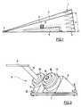
- Fig. 1 shows a section through a conical TEM cell 1, as used to check the electromagnetic Compatibility of test objects is used.
- electromagnetic compatibility one understands electromagnetic immunity on the one hand, i.e. immunity of one piece of equipment against interference radiation emitted by other equipment, and on the other hand, the electromagnetic interference emission, i.e. interference that the equipment in other equipment.
- electromagnetic immunity i.e. immunity of one piece of equipment against interference radiation emitted by other equipment
- the electromagnetic interference emission i.e. interference that the equipment in other equipment.
- This standard specifies that the electromagnetic fields through the use of antennas in reflection-free or almost reflection-free Chambers can be generated, the test specimen of the stress in three Alignments relative to the field in such a way that the electrical (E) - and magnetic (H) - portions of the field on each of the three rectangular axes of the device under test be created.
- a TEM cell is such a reflection-free chamber.
- the conical TEM cell 1 is structurally a closed strip line with an asymmetrical inner conductor 2, the lines from a connection point 3 lead away, which is arranged at the top of the pyramid-shaped cell.
- High-frequency absorbers are located on the base surface of the pyramid opposite the connection point 3 4 provided.
- homogeneous electromagnetic Fields in a frequency range from a few hertz to a few gigahertz are generated become.
- TEM cells also function as receiving antennas for the measurement of radiated electromagnetic interference.
- the Boundary conditions that the test object can be placed anywhere in the cell (total test volume in the middle third) and the test height should be adjustable (test specimen focus on ⁇ / 2, if ⁇ the angle between the inner conductor 2 and the more distant opposite side wall of cell 1), and that in the cell, apart from the test object, only parts are possible Electromagnetic neutral material, so that the homogeneity of the electromagnetic Field is not affected.
- test object is at the correct height, you have so far been on the bottom of cell 1 a wedge-shaped pad 5 made of rigid foam, on which the one with the reference number P designated specimen was pushed into the optimal position.
- optimal means that on the one hand the test object P is as close as possible to the Top of the cell (connection point 3), and on the other hand the edge length of the Test piece P a maximum of one third of the distance between the inner conductor 2 and the bottom of the conical TEM cell should be 1 at the test position.
- the device under test P is on a special one Bracket 6 made of wood fastened with three side surfaces arranged at right angles to one another, which come to rest on edition 5 in succession during the examination. The positioning of the support bracket 6 with the specimen P is done by hand.
- FIGS. 2 and 3 replaces the support 5 and the support bracket 6 and enables automatic adjustment of the test object P into the individual positions.
- the test specimen P only needs to be attached to the test specimen manipulator M before the test and to be removed from it after the test. In between there is no manual Intervention is required so that the test can run automatically.
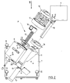
- Fig. 2 shows one Exploded view of the specimen manipulator M in a view from above and
- FIG. 3 shows a front view in the direction of arrow III of FIG. 2nd
- the test specimen manipulator M essentially consists of a base plate 7, a housing 8 arranged thereon, one of a test specimen plate 9 and one of these supporting hollow shaft 10 existing test specimen holder and one arranged on the base plate 7 Support 11, in which the hollow shaft 10 is supported and supported.
- the bottom plate 7 is provided for installation on the bottom of the TEM cell 1 (FIG. 1) and points in the area four vertically adjustable adjusting screws 12 at their corners.
- In the support 11 is one Guide sleeve 13 rotatably mounted, in which the hollow shaft 10 slides in the longitudinal direction and is fixable. It is fixed in the desired position with a clamping bolt 14.
- the hollow shaft 10 runs obliquely upwards from the base plate 1 and is oriented in such a way that its axis runs in a space diagonal of a cube.
- the hollow shaft 10 is provided at its free end with a horizontally beveled head part, onto which the test piece plate 9 is screwed.
- the latter is parallel to the base plate 1 oriented.
- the orientation of the hollow shaft 10 in the spatial diagonal of a cube achieves that a test specimen arranged on the test specimen plate 9 rotates the hollow shaft 10 by 120 ° twice the orientation required by the European standard EN 50130-4 reached to the field where the electrical and magnetic parts of the field in each of the three right-angled axes of the test object.
- the longitudinal displaceability of the Hollow shaft 10 in the guide sleeve 13 is used to adjust the optimal height of the test object P. in the TEM cell with the specimen focus on ⁇ / 2 (Fig. 1). The latter requirement applies however only for conical TEM cells.
- the hollow shaft 10 is rotated in the two steps of 120 ° each by one in the housing 8 arranged pneumatic drive, which by a so-called vane (not shown) is formed.
- This consists of a sealed chamber in the housing 8 with a spline shaft 15 which can be driven by an air cushion and which penetrates the chamber arranged swivel wing 16.
- the housing 8 has the end face, against the test specimen plate 9 out, an opening, which is closed by a lid 17.
- the cover 17 has as well as the rear wall of the chamber opposite the cover 17 has an opening for Passage of the spline shaft 15.
- the wedge shaft protruding from the wing cell with both ends 15 carries at its front end a spline gear 18, which with a on the hollow shaft 10 fixed specimen gear 19 is engaged, and at its rear end a stop lever 20.
- the test specimen gear 19 is on the hollow shaft 10 with a wedge against rotation secured.
- the stop lever 20 limits the rotation of the spline 15 to twice 120 °.
- the two End positions of the stop lever 20, 0 ° and 240 ° are indicated by corresponding stops in the Housing 8 defined.
- a pneumatically operated stop cylinder 21 is provided, optionally in the path of movement of the swivel wing 16 pushed or pushed out of it.
- the pneumatic connections on the housing 8 are through holes A for driving the pivoting wing 16 and B for actuating the Stop cylinder 21 indicated.
- a stationary chamber seal 22 is provided between the chamber wall and the spline shaft 15, through which the chamber is divided into two subchambers. Depending on which one of the two holes A air is supplied, the pivoting wing 16 rotates in one or the other direction.
- the guide sleeve 13 is provided at its rear end with a collar, which at one corresponding gradation of the support 11 is present. So that the guide sleeve 13 and with this connected by the clamping bolt 14 hollow shaft 10 against slipping out of the Support secured in the direction away from the base plate 7. That fixed on the hollow shaft 10 Test gear 19 secures the hollow shaft 10 and the guide sleeve 13 against slipping Bottom plate 7 down.
- the cables to the electrical connections of the test object are through the hollow shaft 10 to the base plate 1 and from there to corresponding connections in cell 1. That has the The advantage is that the cables are protected and do not get caught or get caught in the gears can. In addition, the cables are always routed away from the test object in the same position, which simplifies comparisons between the individual measurements.
- the test specimen manipulator M must consist of a material which does not affect the electromagnetic field in the TEM cell.
- MFD a medium density fiberboard. MFD exists at mostly made of wood and can be worked very well.
- polyacetal POM
- test specimen plate 9 There are a number of possibilities for fastening the test specimen to the test specimen plate 9, that of stretching with a strong rubber band over clamping with suitable ones Tighten the clamping device until it is screwed on. If different test objects have the same housing shape should be tested, it will be worthwhile in most cases, on the test piece plate 9 to mount a suitable base or the like.
- test specimen holders (hollow shafts 10 with screwed on Test plate 9) ready to have one test piece while another is running Attach the test to the test specimen plate 9 and change the test specimens by simple To be able to loosen the clamping bolt 14 and replace the test specimen holder.
- test specimen manipulator M All functions of the specimen manipulator M with the exception of pressure monitoring Pneumatics are controlled by a microcontroller or microprocessor. Every measurement is preferably started by a computer, the test specimen manipulator M by Hand is turned to the starting position, in which the swivel of the test specimen plate is 0 °. Automating this step would include sensors to monitor the position of the Test plate 9 require. Then the measurement begins, after the measurement in the specimen plate 9 is automatically rotated to the next position in a certain position becomes. After completing the measurement in the third position, in which the test piece is twisted Is 240 °, the test piece plate can be automatically turned back to the basic position become. However, it is advisable to leave the test specimen plate in the third position because then the user immediately recognizes whether the test has been carried out properly and whether the DUT manipulator has not jammed.
- test specimen manipulator M in connection with a conical TEM cell is not meant to be a limitation.
- the test specimen manipulator is rather for all types suitable for TEM cells.
Landscapes
- Physics & Mathematics (AREA)
- Electromagnetism (AREA)
- General Physics & Mathematics (AREA)
- Sampling And Sample Adjustment (AREA)
Priority Applications (1)
| Application Number | Priority Date | Filing Date | Title |
|---|---|---|---|
| EP00106304A EP1136831A1 (fr) | 2000-03-23 | 2000-03-23 | Manipulateur de dispositifs à tester pour cellules du type TEM |
Applications Claiming Priority (1)
| Application Number | Priority Date | Filing Date | Title |
|---|---|---|---|
| EP00106304A EP1136831A1 (fr) | 2000-03-23 | 2000-03-23 | Manipulateur de dispositifs à tester pour cellules du type TEM |
Publications (1)
| Publication Number | Publication Date |
|---|---|
| EP1136831A1 true EP1136831A1 (fr) | 2001-09-26 |
Family
ID=8168210
Family Applications (1)
| Application Number | Title | Priority Date | Filing Date |
|---|---|---|---|
| EP00106304A Withdrawn EP1136831A1 (fr) | 2000-03-23 | 2000-03-23 | Manipulateur de dispositifs à tester pour cellules du type TEM |
Country Status (1)
| Country | Link |
|---|---|
| EP (1) | EP1136831A1 (fr) |
Cited By (1)
| Publication number | Priority date | Publication date | Assignee | Title |
|---|---|---|---|---|
| CN117388611A (zh) * | 2023-10-16 | 2024-01-12 | 苏州科标检测有限公司 | 一种电子零部件抗干扰能力的测试装置及测试方法 |
Citations (3)
| Publication number | Priority date | Publication date | Assignee | Title |
|---|---|---|---|---|
| WO1993018558A1 (fr) * | 1992-03-13 | 1993-09-16 | The Electro-Mechanics Company | Appareil de controle des interferences electromagnetiques |
| DE4214585A1 (de) * | 1992-04-28 | 1993-11-04 | Messelektronik Berlin Gmbh | Manipulator zur positionierung von prueflingen bei emv-messungen in 3 orthogonalen richtungen |
| WO1996012198A1 (fr) * | 1994-10-12 | 1996-04-25 | Siemens Business Communication Systems, Inc. | Systeme et procede de mesures electromagnetiques par cellules electromagnetiques transversales |
-
2000
- 2000-03-23 EP EP00106304A patent/EP1136831A1/fr not_active Withdrawn
Patent Citations (3)
| Publication number | Priority date | Publication date | Assignee | Title |
|---|---|---|---|---|
| WO1993018558A1 (fr) * | 1992-03-13 | 1993-09-16 | The Electro-Mechanics Company | Appareil de controle des interferences electromagnetiques |
| DE4214585A1 (de) * | 1992-04-28 | 1993-11-04 | Messelektronik Berlin Gmbh | Manipulator zur positionierung von prueflingen bei emv-messungen in 3 orthogonalen richtungen |
| WO1996012198A1 (fr) * | 1994-10-12 | 1996-04-25 | Siemens Business Communication Systems, Inc. | Systeme et procede de mesures electromagnetiques par cellules electromagnetiques transversales |
Non-Patent Citations (2)
| Title |
|---|
| BRONAUGH E L: "SIMPLIFYING EMI IMMUNITY (SUSCEPTIBILITY) TESTS IN TEM CELLS", PROCEEDINGS OF THE INTERNATIONAL SYMPOSIUM ON ELECTROMAGNETIC COMPATIBILITY,US,NEW YORK, IEEE, vol. -, 21 August 1990 (1990-08-21), pages 488 - 491, XP000224687 * |
| KOEPKE G H ET AL: "IMPLEMENTATION OF AN AUTOMATED SYSTEM FOR MEASURING RADIATED EMISSIONS USING A TEM CELL", IEEE TRANSACTIONS ON INSTRUMENTATION AND MEASUREMENT,US,IEEE INC. NEW YORK, vol. 38, no. 2, 1 April 1989 (1989-04-01), pages 473 - 479, XP000081529, ISSN: 0018-9456 * |
Cited By (2)
| Publication number | Priority date | Publication date | Assignee | Title |
|---|---|---|---|---|
| CN117388611A (zh) * | 2023-10-16 | 2024-01-12 | 苏州科标检测有限公司 | 一种电子零部件抗干扰能力的测试装置及测试方法 |
| CN117388611B (zh) * | 2023-10-16 | 2024-06-11 | 苏州科标检测有限公司 | 一种电子零部件抗干扰能力的测试装置及测试方法 |
Similar Documents
| Publication | Publication Date | Title |
|---|---|---|
| DE69522586T2 (de) | Manipulator für einen testkopf einer automatischen testanlage | |
| EP1697608B1 (fr) | Boitier pour appareil menager | |
| EP3894819B1 (fr) | Ensemble de fixation destiné à fixer un support de dispositif de vérification sur un dispositif de mesure de force, dispositif de mesure de force doté d'un tel ensemble de fixation, support de dispositif de vérification et élément coulisseau pour un dispositif de mesure de force | |
| EP0499943A2 (fr) | Dispositif pour la mise en oeuvre d'éssais par contraintes en flexion alternées à 4 points d'appui | |
| CH688290A5 (de) | Wasserwaage. | |
| EP0338338A2 (fr) | Armoire de commutation à fixation murale | |
| DE2541554C3 (de) | Beschlaganordnung für Kastenmöbel | |
| EP1136831A1 (fr) | Manipulateur de dispositifs à tester pour cellules du type TEM | |
| DE2849794C2 (de) | Tonarm für einen Plattenspieler | |
| DE4417039C2 (de) | Bandaufnahmeelement | |
| DE202009014932U1 (de) | Deckenlift | |
| DE19619739C1 (de) | Vorrichtung zur Höhenverstellung einer Auflagefläche, insbesondere zur Höhenverstellung eines Computerbildschirmes | |
| DE19504257C2 (de) | Lagerhalterung für die Wickelwellen von im Winkel angeordneten und gleichzeitig betätigten Rolläden | |
| DE750422C (de) | Spaltblende zur Ausblendung eines Roentgenstrahlenkegels | |
| EP0015527B1 (fr) | Dispositif pour la fixation de boîtiers dans un bâti | |
| DE3815196A1 (de) | Schwenktafel | |
| DE19746753C2 (de) | Vorrichtung zur Befestigung von Regalelementen | |
| EP0959371A2 (fr) | Profile pour rideau de lumière | |
| DE202021101545U1 (de) | Bruchkammer zum Messen einer Härte eines Prüflings | |
| EP1855079A2 (fr) | Dispositif d'attache pour arranger un instrument de mesure dans un espace | |
| DE3444956A1 (de) | Messtaster | |
| DE10134458A1 (de) | Messsystem zum Messen der optischen Eigenschaften eines Objekts und insbesondere dafür vorgesehener Messkopf | |
| CH650631A5 (de) | Roentgenanlage. | |
| DE3145942A1 (de) | "arbeitstisch mit tischgestell und arbeitsplatte" | |
| DE3712824A1 (de) | Stufenlos verstellbare montagevorrichtung |
Legal Events
| Date | Code | Title | Description |
|---|---|---|---|
| PUAI | Public reference made under article 153(3) epc to a published international application that has entered the european phase |
Free format text: ORIGINAL CODE: 0009012 |
|
| AK | Designated contracting states |
Kind code of ref document: A1 Designated state(s): AT BE CH CY DE DK ES FI FR GB GR IE IT LI LU MC NL PT SE |
|
| AX | Request for extension of the european patent |
Free format text: AL;LT;LV;MK;RO;SI |
|
| AKX | Designation fees paid | ||
| REG | Reference to a national code |
Ref country code: DE Ref legal event code: 8566 |
|
| STAA | Information on the status of an ep patent application or granted ep patent |
Free format text: STATUS: THE APPLICATION IS DEEMED TO BE WITHDRAWN |
|
| 18D | Application deemed to be withdrawn |
Effective date: 20020327 |