EP1136702A2 - Druckwasserversorgung - Google Patents
Druckwasserversorgung Download PDFInfo
- Publication number
- EP1136702A2 EP1136702A2 EP01105014A EP01105014A EP1136702A2 EP 1136702 A2 EP1136702 A2 EP 1136702A2 EP 01105014 A EP01105014 A EP 01105014A EP 01105014 A EP01105014 A EP 01105014A EP 1136702 A2 EP1136702 A2 EP 1136702A2
- Authority
- EP
- European Patent Office
- Prior art keywords
- pressurized water
- consumers
- pressure
- valve
- switched
- Prior art date
- Legal status (The legal status is an assumption and is not a legal conclusion. Google has not performed a legal analysis and makes no representation as to the accuracy of the status listed.)
- Granted
Links
Images
Classifications
-
- F—MECHANICAL ENGINEERING; LIGHTING; HEATING; WEAPONS; BLASTING
- F15—FLUID-PRESSURE ACTUATORS; HYDRAULICS OR PNEUMATICS IN GENERAL
- F15B—SYSTEMS ACTING BY MEANS OF FLUIDS IN GENERAL; FLUID-PRESSURE ACTUATORS, e.g. SERVOMOTORS; DETAILS OF FLUID-PRESSURE SYSTEMS, NOT OTHERWISE PROVIDED FOR
- F15B11/00—Servomotor systems without provision for follow-up action; Circuits therefor
- F15B11/16—Servomotor systems without provision for follow-up action; Circuits therefor with two or more servomotors
- F15B11/161—Servomotor systems without provision for follow-up action; Circuits therefor with two or more servomotors with sensing of servomotor demand or load
- F15B11/165—Servomotor systems without provision for follow-up action; Circuits therefor with two or more servomotors with sensing of servomotor demand or load for adjusting the pump output or bypass in response to demand
-
- F—MECHANICAL ENGINEERING; LIGHTING; HEATING; WEAPONS; BLASTING
- F04—POSITIVE - DISPLACEMENT MACHINES FOR LIQUIDS; PUMPS FOR LIQUIDS OR ELASTIC FLUIDS
- F04B—POSITIVE-DISPLACEMENT MACHINES FOR LIQUIDS; PUMPS
- F04B49/00—Control, e.g. of pump delivery, or pump pressure of, or safety measures for, machines, pumps, or pumping installations, not otherwise provided for, or of interest apart from, groups F04B1/00 - F04B47/00
- F04B49/02—Stopping, starting, unloading or idling control
- F04B49/03—Stopping, starting, unloading or idling control by means of valves
- F04B49/035—Bypassing
-
- F—MECHANICAL ENGINEERING; LIGHTING; HEATING; WEAPONS; BLASTING
- F15—FLUID-PRESSURE ACTUATORS; HYDRAULICS OR PNEUMATICS IN GENERAL
- F15B—SYSTEMS ACTING BY MEANS OF FLUIDS IN GENERAL; FLUID-PRESSURE ACTUATORS, e.g. SERVOMOTORS; DETAILS OF FLUID-PRESSURE SYSTEMS, NOT OTHERWISE PROVIDED FOR
- F15B2211/00—Circuits for servomotor systems
- F15B2211/20—Fluid pressure source, e.g. accumulator or variable axial piston pump
- F15B2211/205—Systems with pumps
- F15B2211/2053—Type of pump
- F15B2211/20538—Type of pump constant capacity
-
- F—MECHANICAL ENGINEERING; LIGHTING; HEATING; WEAPONS; BLASTING
- F15—FLUID-PRESSURE ACTUATORS; HYDRAULICS OR PNEUMATICS IN GENERAL
- F15B—SYSTEMS ACTING BY MEANS OF FLUIDS IN GENERAL; FLUID-PRESSURE ACTUATORS, e.g. SERVOMOTORS; DETAILS OF FLUID-PRESSURE SYSTEMS, NOT OTHERWISE PROVIDED FOR
- F15B2211/00—Circuits for servomotor systems
- F15B2211/40—Flow control
- F15B2211/41—Flow control characterised by the positions of the valve element
- F15B2211/411—Flow control characterised by the positions of the valve element the positions being discrete
-
- F—MECHANICAL ENGINEERING; LIGHTING; HEATING; WEAPONS; BLASTING
- F15—FLUID-PRESSURE ACTUATORS; HYDRAULICS OR PNEUMATICS IN GENERAL
- F15B—SYSTEMS ACTING BY MEANS OF FLUIDS IN GENERAL; FLUID-PRESSURE ACTUATORS, e.g. SERVOMOTORS; DETAILS OF FLUID-PRESSURE SYSTEMS, NOT OTHERWISE PROVIDED FOR
- F15B2211/00—Circuits for servomotor systems
- F15B2211/40—Flow control
- F15B2211/415—Flow control characterised by the connections of the flow control means in the circuit
- F15B2211/41509—Flow control characterised by the connections of the flow control means in the circuit being connected to a pressure source and a directional control valve
-
- F—MECHANICAL ENGINEERING; LIGHTING; HEATING; WEAPONS; BLASTING
- F15—FLUID-PRESSURE ACTUATORS; HYDRAULICS OR PNEUMATICS IN GENERAL
- F15B—SYSTEMS ACTING BY MEANS OF FLUIDS IN GENERAL; FLUID-PRESSURE ACTUATORS, e.g. SERVOMOTORS; DETAILS OF FLUID-PRESSURE SYSTEMS, NOT OTHERWISE PROVIDED FOR
- F15B2211/00—Circuits for servomotor systems
- F15B2211/40—Flow control
- F15B2211/42—Flow control characterised by the type of actuation
- F15B2211/426—Flow control characterised by the type of actuation electrically or electronically
-
- F—MECHANICAL ENGINEERING; LIGHTING; HEATING; WEAPONS; BLASTING
- F15—FLUID-PRESSURE ACTUATORS; HYDRAULICS OR PNEUMATICS IN GENERAL
- F15B—SYSTEMS ACTING BY MEANS OF FLUIDS IN GENERAL; FLUID-PRESSURE ACTUATORS, e.g. SERVOMOTORS; DETAILS OF FLUID-PRESSURE SYSTEMS, NOT OTHERWISE PROVIDED FOR
- F15B2211/00—Circuits for servomotor systems
- F15B2211/40—Flow control
- F15B2211/47—Flow control in one direction only
- F15B2211/473—Flow control in one direction only without restriction in the reverse direction
-
- F—MECHANICAL ENGINEERING; LIGHTING; HEATING; WEAPONS; BLASTING
- F15—FLUID-PRESSURE ACTUATORS; HYDRAULICS OR PNEUMATICS IN GENERAL
- F15B—SYSTEMS ACTING BY MEANS OF FLUIDS IN GENERAL; FLUID-PRESSURE ACTUATORS, e.g. SERVOMOTORS; DETAILS OF FLUID-PRESSURE SYSTEMS, NOT OTHERWISE PROVIDED FOR
- F15B2211/00—Circuits for servomotor systems
- F15B2211/50—Pressure control
- F15B2211/505—Pressure control characterised by the type of pressure control means
- F15B2211/50509—Pressure control characterised by the type of pressure control means the pressure control means controlling a pressure upstream of the pressure control means
- F15B2211/50518—Pressure control characterised by the type of pressure control means the pressure control means controlling a pressure upstream of the pressure control means using pressure relief valves
-
- F—MECHANICAL ENGINEERING; LIGHTING; HEATING; WEAPONS; BLASTING
- F15—FLUID-PRESSURE ACTUATORS; HYDRAULICS OR PNEUMATICS IN GENERAL
- F15B—SYSTEMS ACTING BY MEANS OF FLUIDS IN GENERAL; FLUID-PRESSURE ACTUATORS, e.g. SERVOMOTORS; DETAILS OF FLUID-PRESSURE SYSTEMS, NOT OTHERWISE PROVIDED FOR
- F15B2211/00—Circuits for servomotor systems
- F15B2211/50—Pressure control
- F15B2211/505—Pressure control characterised by the type of pressure control means
- F15B2211/50554—Pressure control characterised by the type of pressure control means the pressure control means controlling a pressure downstream of the pressure control means, e.g. pressure reducing valve
-
- F—MECHANICAL ENGINEERING; LIGHTING; HEATING; WEAPONS; BLASTING
- F15—FLUID-PRESSURE ACTUATORS; HYDRAULICS OR PNEUMATICS IN GENERAL
- F15B—SYSTEMS ACTING BY MEANS OF FLUIDS IN GENERAL; FLUID-PRESSURE ACTUATORS, e.g. SERVOMOTORS; DETAILS OF FLUID-PRESSURE SYSTEMS, NOT OTHERWISE PROVIDED FOR
- F15B2211/00—Circuits for servomotor systems
- F15B2211/50—Pressure control
- F15B2211/51—Pressure control characterised by the positions of the valve element
- F15B2211/513—Pressure control characterised by the positions of the valve element the positions being continuously variable, e.g. as realised by proportional valves
-
- F—MECHANICAL ENGINEERING; LIGHTING; HEATING; WEAPONS; BLASTING
- F15—FLUID-PRESSURE ACTUATORS; HYDRAULICS OR PNEUMATICS IN GENERAL
- F15B—SYSTEMS ACTING BY MEANS OF FLUIDS IN GENERAL; FLUID-PRESSURE ACTUATORS, e.g. SERVOMOTORS; DETAILS OF FLUID-PRESSURE SYSTEMS, NOT OTHERWISE PROVIDED FOR
- F15B2211/00—Circuits for servomotor systems
- F15B2211/50—Pressure control
- F15B2211/515—Pressure control characterised by the connections of the pressure control means in the circuit
- F15B2211/5157—Pressure control characterised by the connections of the pressure control means in the circuit being connected to a pressure source and a return line
-
- F—MECHANICAL ENGINEERING; LIGHTING; HEATING; WEAPONS; BLASTING
- F15—FLUID-PRESSURE ACTUATORS; HYDRAULICS OR PNEUMATICS IN GENERAL
- F15B—SYSTEMS ACTING BY MEANS OF FLUIDS IN GENERAL; FLUID-PRESSURE ACTUATORS, e.g. SERVOMOTORS; DETAILS OF FLUID-PRESSURE SYSTEMS, NOT OTHERWISE PROVIDED FOR
- F15B2211/00—Circuits for servomotor systems
- F15B2211/50—Pressure control
- F15B2211/52—Pressure control characterised by the type of actuation
- F15B2211/526—Pressure control characterised by the type of actuation electrically or electronically
-
- F—MECHANICAL ENGINEERING; LIGHTING; HEATING; WEAPONS; BLASTING
- F15—FLUID-PRESSURE ACTUATORS; HYDRAULICS OR PNEUMATICS IN GENERAL
- F15B—SYSTEMS ACTING BY MEANS OF FLUIDS IN GENERAL; FLUID-PRESSURE ACTUATORS, e.g. SERVOMOTORS; DETAILS OF FLUID-PRESSURE SYSTEMS, NOT OTHERWISE PROVIDED FOR
- F15B2211/00—Circuits for servomotor systems
- F15B2211/50—Pressure control
- F15B2211/52—Pressure control characterised by the type of actuation
- F15B2211/528—Pressure control characterised by the type of actuation actuated by fluid pressure
-
- F—MECHANICAL ENGINEERING; LIGHTING; HEATING; WEAPONS; BLASTING
- F15—FLUID-PRESSURE ACTUATORS; HYDRAULICS OR PNEUMATICS IN GENERAL
- F15B—SYSTEMS ACTING BY MEANS OF FLUIDS IN GENERAL; FLUID-PRESSURE ACTUATORS, e.g. SERVOMOTORS; DETAILS OF FLUID-PRESSURE SYSTEMS, NOT OTHERWISE PROVIDED FOR
- F15B2211/00—Circuits for servomotor systems
- F15B2211/60—Circuit components or control therefor
- F15B2211/63—Electronic controllers
- F15B2211/6303—Electronic controllers using input signals
- F15B2211/6306—Electronic controllers using input signals representing a pressure
- F15B2211/6309—Electronic controllers using input signals representing a pressure the pressure being a pressure source supply pressure
Definitions
- the invention relates to a pressurized water supply - whereby the term pressurized water also includes other hydraulic pressure media includes - with several parallel that can be switched on and off separately Pressurized water consumers, one of the pressurized water consumers Excess parallel overflow arrangement for discharge Pressure water and a pump unit with controllable Output.
- a tried and tested pressurized water supply of the type specified at the beginning Art owns a pump unit, its delivery rate constantly the maximum demand of the connected pressure water consumers exceeds, i.e. it is constantly pressurized water funded in excess, and depending on the number of simultaneously working pressure water consumers changing Excess is discharged through the overflow arrangement. This is controlled depending on the pressure of the pressurized water or regulated, such that the pressure of the pressurized water even when one or more of the connected pressure water consumers only comparatively can fluctuate slightly.
- Such a pressurized water supply is distinguished through simple construction and control.
- the system works with undesirably high power losses, which complicates the fact that the pressurized water supply compared to the maximum demand of the connected Pressurized water consumers must be oversized. Accordingly, both the operating costs and the Manufacturing costs high.
- DE-OS 24 13 295 now shows one with regard to the flow rate as well as the pressure on the pump pressure side adjustable Pump, although not excluded at any point is that in all operating states of the connected to the pump Pressure system pressure medium via a pressure relief valve is dissipated, which accordingly at high Pressing and / or for media that are used for cavitation tend to be subject to high wear, which then only can be compensated for by increased pump delivery could.
- the object of the invention is now the economy of a Pressurized water supply of the type specified at the beginning increase, on the one hand long operating times without inspections and on the other hand a little effort for control or regulation should be made possible.
- the Pump unit when all consumers are switched on and shutdown Overflow arrangement for needs-based conveying capacity is adjustable or adjustable that when switched off one or more of the connected pressure water consumers the aforementioned delivery rate at least essentially remains unchanged and the overflow arrangement one given by the switched off pressure water consumers Discharges pressure water quantity, and that the overflow arrangement Shut-off valve and a controllable one arranged in series Overflow valve has its maximum throttle resistance is greater than the throttle resistance of the pressure water consumer with maximum throttle resistance.
- the invention is based on the general idea, on the one hand to control or regulate the pump set and thus the pumping capacity of the pump set to the maximum requirement of the connected pressurized water consumers and on the other hand when one or more of the Pressurized water consumers when all pressurized water consumers are switched on blocked overflow arrangement more or less open to the pressurized water consumers derive non-absorbed pressurized water.
- In the invention is a safe control or regulation guaranteed because in all operating states of the system only one unit at a time, either the pump unit or the overflow arrangement, controlled or regulated.
- shut-off valve Between the closed and open position of the shut-off valve can can be switched extremely quickly. Furthermore the overflow valve quickly adjusts to requirements, because it can stay open all the time.
- shut-off valve i.e. when all are switched on pressurized water consumers connected to the pressurized water supply, no wear and tear. This applies even if the number of actually connected Consumer is less than the maximum number of connectable Consumers, i.e. if not all consumer connections the pressurized water supply are actually occupied.
- shut-off valves arranged at the pressurized water supply. It is preferred provided, these shut-off valves near the pump unit to be arranged or integrated into the pump set and to connect the pressure water consumers with the connection lines provided for the pressurized water supply to make the shut-off valve depressurized.
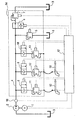
- the only figure shows a circuit diagram-like representation a pressurized water supply according to the invention.
- a motor 1 which is controllable Speed works
- a pump 2 which acts as a pressure source is intended for pressurized water and water from a Reservoir 3 connected on the suction side to the pump 2 into a Distribution line connected to pump 2 on the pressure side 4 promotes for pressurized water.
- the distribution line 4 has several branches, each by a normally closed, seat-controlled Shut-off valve 8.9 or 10 and one in series switched, preferably gap-controlled pressure control valve 11, 12 or 13, the purpose of which is explained below, controlled become.
- valve block 14 The aforementioned valves can form a compact valve block 14 be summarized.
- the pressure relief valve 5 and the overflow valve 7 can be connected on the output side to the reservoir 3. However it is also possible for the water to flow out or overflow to avoid heating the reservoir 3 to the outside conduct.
- shut-off valves 8 to 10 in the example shown downstream pressure control valves 11 to 13 can be on the output side via pressure hoses with pressure water consumers, are connected to spray lances 15 in the example shown, as usual for the removal of ailing material on buildings are.
- a central control unit 17 controls the motor on the one hand 1 and on the other hand the valves 6 to 13. In addition, the Control unit 17. With the actuators of the spray lances 15.16 or the like. connected, the control unit 17 on the one hand the total number of connected spray lances 15.16 or pressure water consumer recognizes and on the other hand the condition the operating elements of the spray lances 15, 16 or Pressurized water consumers recorded.
- the engine 1 is from the control unit 17 to such a working speed or speed adjusted that in the pressurized water distribution line 4 a detectable by means of a pressure sensor 18 Pressure corresponding to one for the respective pressure medium consumer sets the specified target pressure.
- This engine setting is stored by the control unit 17.
- the control unit 17 receives a corresponding switch-off signal and blocks the spray lance 15 assigned shut-off valve 8.
- the shut-off valve 6 opened and the downstream overflow valve 7, which is designed as a controllable throttle valve is controlled so that the predetermined pressure in the pressurized water distribution line 4 is maintained, namely with unchanged power of engine 1, i.e. the setting the motor control and thus the delivery rate of the Pump 2 remain compared to the condition described above - All connected spray lances 15, 16 work parallel - unchanged.
- the overflow valve 7 is the result set to a throttle resistance that is the throttle resistance the switched off spray lance during spraying operation corresponds. If several of the connected spray lances 15,16 are turned off, the throttle resistance the overflow valve 7 is set to a reduced value, which is the throttle resistance of the switched off Spray lances in parallel operation corresponds.
- the control unit 17 receives a corresponding one Activation signal and opens the spray lance 15th assigned shut-off valve 8.
- the shut-off valve 8 opens the downstream pressure control valve 11, which like the other pressure control valves 12 and 13 controllable throttle valve, however, its completely open position only if the pressure is approximately equal on the inlet and outlet side of the pressure control valve can achieve from its severely throttled state increasingly switched to the open state. This reversal takes place in such a way that the desired pressure in the Pressurized water distribution line 4 is maintained independently whether the long pressure hose, if necessary the spray lance 15 is free of pressure before opening the shut-off valve 8 was or not.
- Spray lances 15, 16 are switched off and on again, the power of the motor 1 or the pump 2 readjusted can be as soon as all connected Spray lances 15, 16 work.
- the readjusted state remains saved.
- control unit 17 can be designed or be programmed that different when starting up Learning or testing phases must be carried out:
- the control unit 17 can thus switch on a learning phase force in which all connected consumers or Spray lances 15, 16 are put into operation simultaneously have to.
- the control unit 17 can the engine 1 with the Pump 2 briefly on the maximum pressure water consumption adjust and adjust the corresponding operating parameters of the Motors 1 (possibly also pump 2) "remember" so that In the later spraying operation, insignificant at most Adaptations become necessary.
- the pressure control valves 11, 12, 13 can also be on the inlet side the shut-off valves 8,9,10 can be arranged.
- shut-off valve 6 can also be on the outlet side of the overflow valve 7 may be arranged.
Landscapes
- Engineering & Computer Science (AREA)
- Mechanical Engineering (AREA)
- General Engineering & Computer Science (AREA)
- Physics & Mathematics (AREA)
- Fluid Mechanics (AREA)
- Control Of Positive-Displacement Pumps (AREA)
- Toys (AREA)
- Domestic Plumbing Installations (AREA)
- Fluid-Pressure Circuits (AREA)
- Percussion Or Vibration Massage (AREA)
- Sanitary Device For Flush Toilet (AREA)
- Nozzles (AREA)
- Fire-Extinguishing By Fire Departments, And Fire-Extinguishing Equipment And Control Thereof (AREA)
Abstract
Description
Claims (7)
- Druckwasserversorgung mit mehreren separat zu- und abschaltbaren parallelen Druckwasserverbrauchern (15,16), einer zu den Druckwasserverbrauchern parallelen Überströmanordnung (6,7) zur Ableitung überschüssigen Druckwassers sowie einem Pumpenaggregat (1,2) mit steuerbarer Fördermenge, wobeidas Pumpenaggregat (1,2) bei Zuschaltung aller Verbraucher (15,16) sowie abgesperrter Überströmanordnung auf bedarfsgerechte Förderleistung einstellbar bzw. einregelbar ist,bei Abschaltung eines oder mehrerer der angeschlossenen Druckwasserverbraucher (15,16) die vorgenannte Förderleistung zumindest im wesentlichen unverändert bleibt und die Überströmanordnung (6,7) eine durch die abgeschalteten Druckwasserverbraucher vorgegebene Druckwassermenge abführt, unddie Überströmanordnung (6,7) ein Absperrventil (6) sowie ein dazu in Reihe angeordnetes steuerbares Überströmventil (7) aufweist, dessen maximaler Drosselwiderstand größer ist als der Drosselwiderstand des Druckwasserverbrauchers mit maximalem Drosselwiderstand.
- Druckwasserversorgung mit mehreren separat zu- und abschaltbaren parallelen Druckwasserverbrauchern (15,16), einer zu den Druckwasserverbrauchern parallelen Überströmanordnung (6,7) zur Ableitung überschüssigen Druckwassers sowie einem Pumpenaggregat (1,2) mit steuerbarer Fördermenge, insbesondere nach Anspruch 1,
dadurch gekennzeichnet, daß jeder Verbraucher (15,16) über ein gesondertes Absperrventil (8,9,10) sowie ein dazu in Reihe angeordnetes Druckhalteventil (11,12,13) zuschaltbar ist. - Druckwasserversorgung nach Anspruch 1 oder 2,
dadurch gekennzeichnet, daß alle Absperrventile (5,8,9,10) sitzgesteuert sind. - Druckwasserversorgung nach einem der Ansprüche 1 bis 3,
dadurch gekennzeichnet, daß das Überströmventil (7) und/oder die Druckhalteventile (8,9,10) spaltgesteuert sind. - Druckwasserversorgung nach einem der Ansprüche 1 bis 4,
dadurch gekennzeichnet, daß eine Steuereinheit (17) bei Zuschaltung aller angeschlossenen Verbraucher (15,16) die Überströmanordnung (6,7) absperrt und die Pumpenanordnung (1,2) bzw. deren Antrieb (1) zur Aufrechterhaltung eines vorgegebenen Druckes regelt. - Druckwasserversorgung nach einem der Ansprüche 1 bis 5,
dadurch gekennzeichnet, daß bei Abschaltung zumindest eines der angeschlossenen Verbraucher (15,16) die Pumpenanordnung (1,2) bzw. deren Antrieb (1) von der Steuereinheit (17) nahe einer Leistung für Zuschaltung aller angeschlossenen Verbraucher gehalten und zur Aufrechterhaltung eines vorgegebenen Druckes die Überströmanordnung (6,7) entsprechend betätigt wird. - Druckwasserversorgung nach einem der Ansprüche 1 bis 6,
dadurch gekennzeichnet, daß eine zentrale Steuereinheit (17) die Anzahl der angeschlossenen Druckwasserverbraucher (15,16) erfaßt.
Applications Claiming Priority (2)
| Application Number | Priority Date | Filing Date | Title |
|---|---|---|---|
| DE10014045A DE10014045B4 (de) | 2000-03-23 | 2000-03-23 | Druckwasserversorgung |
| DE10014045 | 2000-03-23 |
Publications (3)
| Publication Number | Publication Date |
|---|---|
| EP1136702A2 true EP1136702A2 (de) | 2001-09-26 |
| EP1136702A3 EP1136702A3 (de) | 2003-09-10 |
| EP1136702B1 EP1136702B1 (de) | 2005-05-18 |
Family
ID=7635812
Family Applications (1)
| Application Number | Title | Priority Date | Filing Date |
|---|---|---|---|
| EP01105014A Expired - Lifetime EP1136702B1 (de) | 2000-03-23 | 2001-03-01 | Druckwasserversorgung |
Country Status (3)
| Country | Link |
|---|---|
| EP (1) | EP1136702B1 (de) |
| AT (1) | ATE295942T1 (de) |
| DE (2) | DE10014045B4 (de) |
Cited By (3)
| Publication number | Priority date | Publication date | Assignee | Title |
|---|---|---|---|---|
| EP1898095A1 (de) * | 2006-09-06 | 2008-03-12 | Claudio Rossner | Steuereinheit für Belüftungseinrichtung |
| CN113757200A (zh) * | 2021-08-31 | 2021-12-07 | 三一汽车制造有限公司 | 一种液压系统、工程机械及其控制方法 |
| WO2024113948A1 (zh) * | 2022-11-30 | 2024-06-06 | 福建侨龙应急装备股份有限公司 | 一种液压系统、供排水车及液压系统控制方法 |
Families Citing this family (1)
| Publication number | Priority date | Publication date | Assignee | Title |
|---|---|---|---|---|
| DE102014100530A1 (de) | 2014-01-17 | 2015-07-23 | Alfred Kärcher Gmbh & Co. Kg | Schaltventilvorrichtung und Hochdruckflüssigkeitsanlage umfassend eine Schaltventilvorrichtung |
Citations (2)
| Publication number | Priority date | Publication date | Assignee | Title |
|---|---|---|---|---|
| DE2413295A1 (de) | 1974-03-20 | 1975-10-02 | Bosch Gmbh Robert | Regeleinrichtung fuer eine verstellbare pumpe |
| DE29516166U1 (de) | 1995-10-12 | 1996-01-11 | Wap Reinigungssysteme Gmbh & Co, 89287 Bellenberg | Druckerzeugungsgerät mit Druckabschaltung und Bypass |
Family Cites Families (4)
| Publication number | Priority date | Publication date | Assignee | Title |
|---|---|---|---|---|
| SE7406518L (sv) * | 1974-05-16 | 1975-11-17 | Euroclean Ab | Regleringsanordning for en tvettningsanleggning. |
| US4593858A (en) * | 1985-04-01 | 1986-06-10 | Butterworth, Inc. | Fail-safe high pressure fluid delivery system |
| FR2686813B1 (fr) * | 1992-02-05 | 1994-05-06 | Joly Gilles | Systeme de distribution d'eau amenee a haute pression et recuperation de cette eau et de dechets occasionnes par le decapage. |
| JP3664733B2 (ja) * | 1995-07-10 | 2005-06-29 | 日立建機株式会社 | 油圧駆動装置 |
-
2000
- 2000-03-23 DE DE10014045A patent/DE10014045B4/de not_active Expired - Fee Related
-
2001
- 2001-03-01 AT AT01105014T patent/ATE295942T1/de not_active IP Right Cessation
- 2001-03-01 EP EP01105014A patent/EP1136702B1/de not_active Expired - Lifetime
- 2001-03-01 DE DE50106241T patent/DE50106241D1/de not_active Expired - Fee Related
Patent Citations (2)
| Publication number | Priority date | Publication date | Assignee | Title |
|---|---|---|---|---|
| DE2413295A1 (de) | 1974-03-20 | 1975-10-02 | Bosch Gmbh Robert | Regeleinrichtung fuer eine verstellbare pumpe |
| DE29516166U1 (de) | 1995-10-12 | 1996-01-11 | Wap Reinigungssysteme Gmbh & Co, 89287 Bellenberg | Druckerzeugungsgerät mit Druckabschaltung und Bypass |
Non-Patent Citations (1)
| Title |
|---|
| "DANFOSS JOURNALEN", no. 4, 1975, pages 4 - 5 |
Cited By (4)
| Publication number | Priority date | Publication date | Assignee | Title |
|---|---|---|---|---|
| EP1898095A1 (de) * | 2006-09-06 | 2008-03-12 | Claudio Rossner | Steuereinheit für Belüftungseinrichtung |
| CN113757200A (zh) * | 2021-08-31 | 2021-12-07 | 三一汽车制造有限公司 | 一种液压系统、工程机械及其控制方法 |
| CN113757200B (zh) * | 2021-08-31 | 2023-05-12 | 三一汽车制造有限公司 | 一种液压系统、工程机械及其控制方法 |
| WO2024113948A1 (zh) * | 2022-11-30 | 2024-06-06 | 福建侨龙应急装备股份有限公司 | 一种液压系统、供排水车及液压系统控制方法 |
Also Published As
| Publication number | Publication date |
|---|---|
| DE10014045B4 (de) | 2005-05-25 |
| DE50106241D1 (de) | 2005-06-23 |
| EP1136702A3 (de) | 2003-09-10 |
| EP1136702B1 (de) | 2005-05-18 |
| DE10014045A1 (de) | 2001-10-11 |
| ATE295942T1 (de) | 2005-06-15 |
Similar Documents
| Publication | Publication Date | Title |
|---|---|---|
| EP1915538B1 (de) | Schaltung zur ansteuerung eines doppeltwirkenden hydraulischen antriebszylinders | |
| DE102017106693B3 (de) | Vorrichtung zum Regeln einer hydraulischen Maschine | |
| EP3601806B1 (de) | Vorrichtung zum regeln einer hydraulischen maschine | |
| EP3748168B1 (de) | Hydraulisches antriebssystem mit zwei pumpen und energierückgewinnung | |
| DE3443265A1 (de) | Regelventil fuer eine verstellpumpe | |
| WO2018108615A1 (de) | Hydraulischer antrieb mit eil- und lasthub | |
| EP1710445A2 (de) | Hydraulische Steuerung | |
| DE102010014071B4 (de) | Hydraulische Anlage | |
| EP0935713A1 (de) | Ventilanordnung und verfahren zur ansteuerung einer derartigen ventilanordnung | |
| EP1136702B1 (de) | Druckwasserversorgung | |
| EP3135924B1 (de) | Hydrauliksteuerung | |
| EP1629156A1 (de) | Hydraulische steueranordnung | |
| DE102010055716B4 (de) | Hydraulischer Antrieb | |
| DE19542275B4 (de) | Vorzugsstromschaltung | |
| DE102009012752A1 (de) | Ventil | |
| DE2753439C2 (de) | ||
| EP3244072A1 (de) | Hydrostatische ventilanordnung und hydrostatische hebevorrichtung mit der ventilanordnung | |
| EP0890030B1 (de) | Sicherheitsschaltung | |
| DE2808032C2 (de) | ||
| EP1837529B1 (de) | Hydraulische Steuervorrichtung | |
| EP2674626B1 (de) | Hydraulikschaltung | |
| DE19948973B4 (de) | Druckabschaltventil | |
| DE202005006719U1 (de) | Pumpvorrichtung | |
| DE19844001A1 (de) | Hydraulisch betätigbare Armatur | |
| EP2339185B1 (de) | Hydrauliksteuerung |
Legal Events
| Date | Code | Title | Description |
|---|---|---|---|
| PUAI | Public reference made under article 153(3) epc to a published international application that has entered the european phase |
Free format text: ORIGINAL CODE: 0009012 |
|
| AK | Designated contracting states |
Kind code of ref document: A2 Designated state(s): AT BE CH CY DE DK ES FI FR GB GR IE IT LI LU MC NL PT SE TR |
|
| AX | Request for extension of the european patent |
Free format text: AL;LT;LV;MK;RO;SI |
|
| PUAL | Search report despatched |
Free format text: ORIGINAL CODE: 0009013 |
|
| AK | Designated contracting states |
Kind code of ref document: A3 Designated state(s): AT BE CH CY DE DK ES FI FR GB GR IE IT LI LU MC NL PT SE TR |
|
| AX | Request for extension of the european patent |
Extension state: AL LT LV MK RO SI |
|
| 17P | Request for examination filed |
Effective date: 20040203 |
|
| AKX | Designation fees paid |
Designated state(s): AT DE FI FR IT NL |
|
| GRAP | Despatch of communication of intention to grant a patent |
Free format text: ORIGINAL CODE: EPIDOSNIGR1 |
|
| GRAS | Grant fee paid |
Free format text: ORIGINAL CODE: EPIDOSNIGR3 |
|
| GRAA | (expected) grant |
Free format text: ORIGINAL CODE: 0009210 |
|
| AK | Designated contracting states |
Kind code of ref document: B1 Designated state(s): AT DE FI FR IT NL |
|
| PG25 | Lapsed in a contracting state [announced via postgrant information from national office to epo] |
Ref country code: IT Free format text: LAPSE BECAUSE OF FAILURE TO SUBMIT A TRANSLATION OF THE DESCRIPTION OR TO PAY THE FEE WITHIN THE PRESCRIBED TIME-LIMIT;WARNING: LAPSES OF ITALIAN PATENTS WITH EFFECTIVE DATE BEFORE 2007 MAY HAVE OCCURRED AT ANY TIME BEFORE 2007. THE CORRECT EFFECTIVE DATE MAY BE DIFFERENT FROM THE ONE RECORDED. Effective date: 20050518 Ref country code: FI Free format text: LAPSE BECAUSE OF FAILURE TO SUBMIT A TRANSLATION OF THE DESCRIPTION OR TO PAY THE FEE WITHIN THE PRESCRIBED TIME-LIMIT Effective date: 20050518 |
|
| REG | Reference to a national code |
Ref country code: IE Ref legal event code: FG4D Free format text: LANGUAGE OF EP DOCUMENT: GERMAN |
|
| REF | Corresponds to: |
Ref document number: 50106241 Country of ref document: DE Date of ref document: 20050623 Kind code of ref document: P |
|
| PGFP | Annual fee paid to national office [announced via postgrant information from national office to epo] |
Ref country code: DE Payment date: 20060116 Year of fee payment: 6 |
|
| PGFP | Annual fee paid to national office [announced via postgrant information from national office to epo] |
Ref country code: AT Payment date: 20060321 Year of fee payment: 6 Ref country code: NL Payment date: 20060321 Year of fee payment: 6 |
|
| PLBE | No opposition filed within time limit |
Free format text: ORIGINAL CODE: 0009261 |
|
| STAA | Information on the status of an ep patent application or granted ep patent |
Free format text: STATUS: NO OPPOSITION FILED WITHIN TIME LIMIT |
|
| 26N | No opposition filed |
Effective date: 20060221 |
|
| EN | Fr: translation not filed | ||
| PG25 | Lapsed in a contracting state [announced via postgrant information from national office to epo] |
Ref country code: AT Free format text: LAPSE BECAUSE OF NON-PAYMENT OF DUE FEES Effective date: 20070301 |
|
| NLV4 | Nl: lapsed or anulled due to non-payment of the annual fee |
Effective date: 20071001 |
|
| PG25 | Lapsed in a contracting state [announced via postgrant information from national office to epo] |
Ref country code: NL Free format text: LAPSE BECAUSE OF NON-PAYMENT OF DUE FEES Effective date: 20071001 Ref country code: DE Free format text: LAPSE BECAUSE OF NON-PAYMENT OF DUE FEES Effective date: 20071002 |
|
| PG25 | Lapsed in a contracting state [announced via postgrant information from national office to epo] |
Ref country code: FR Free format text: LAPSE BECAUSE OF FAILURE TO SUBMIT A TRANSLATION OF THE DESCRIPTION OR TO PAY THE FEE WITHIN THE PRESCRIBED TIME-LIMIT Effective date: 20050518 |