EP1136696B1 - Procédé et dispositif de positionnement d'un moteur thermique, dans une position d'arrêt facilitant le démarrage - Google Patents
Procédé et dispositif de positionnement d'un moteur thermique, dans une position d'arrêt facilitant le démarrage Download PDFInfo
- Publication number
- EP1136696B1 EP1136696B1 EP01400722A EP01400722A EP1136696B1 EP 1136696 B1 EP1136696 B1 EP 1136696B1 EP 01400722 A EP01400722 A EP 01400722A EP 01400722 A EP01400722 A EP 01400722A EP 1136696 B1 EP1136696 B1 EP 1136696B1
- Authority
- EP
- European Patent Office
- Prior art keywords
- engine
- crankshaft
- thermal engine
- speed
- angular position
- Prior art date
- Legal status (The legal status is an assumption and is not a legal conclusion. Google has not performed a legal analysis and makes no representation as to the accuracy of the status listed.)
- Expired - Lifetime
Links
- 238000000034 method Methods 0.000 title claims description 24
- 238000002485 combustion reaction Methods 0.000 title description 3
- 230000002349 favourable effect Effects 0.000 title description 2
- 230000002441 reversible effect Effects 0.000 claims description 8
- 230000000737 periodic effect Effects 0.000 claims description 3
- 230000003068 static effect Effects 0.000 claims description 3
- 210000000056 organ Anatomy 0.000 description 3
- 238000013459 approach Methods 0.000 description 2
- 238000010586 diagram Methods 0.000 description 2
- 239000007858 starting material Substances 0.000 description 2
- 238000009776 industrial production Methods 0.000 description 1
- 230000001131 transforming effect Effects 0.000 description 1
Images

Classifications
-
- F—MECHANICAL ENGINEERING; LIGHTING; HEATING; WEAPONS; BLASTING
- F02—COMBUSTION ENGINES; HOT-GAS OR COMBUSTION-PRODUCT ENGINE PLANTS
- F02N—STARTING OF COMBUSTION ENGINES; STARTING AIDS FOR SUCH ENGINES, NOT OTHERWISE PROVIDED FOR
- F02N19/00—Starting aids for combustion engines, not otherwise provided for
- F02N19/005—Aiding engine start by starting from a predetermined position, e.g. pre-positioning or reverse rotation
-
- F—MECHANICAL ENGINEERING; LIGHTING; HEATING; WEAPONS; BLASTING
- F01—MACHINES OR ENGINES IN GENERAL; ENGINE PLANTS IN GENERAL; STEAM ENGINES
- F01B—MACHINES OR ENGINES, IN GENERAL OR OF POSITIVE-DISPLACEMENT TYPE, e.g. STEAM ENGINES
- F01B27/00—Starting of machines or engines
- F01B27/02—Starting of machines or engines of reciprocating-piston engines
- F01B27/08—Means for moving crank off dead-centre
-
- F—MECHANICAL ENGINEERING; LIGHTING; HEATING; WEAPONS; BLASTING
- F02—COMBUSTION ENGINES; HOT-GAS OR COMBUSTION-PRODUCT ENGINE PLANTS
- F02D—CONTROLLING COMBUSTION ENGINES
- F02D41/00—Electrical control of supply of combustible mixture or its constituents
- F02D41/009—Electrical control of supply of combustible mixture or its constituents using means for generating position or synchronisation signals
-
- F—MECHANICAL ENGINEERING; LIGHTING; HEATING; WEAPONS; BLASTING
- F02—COMBUSTION ENGINES; HOT-GAS OR COMBUSTION-PRODUCT ENGINE PLANTS
- F02D—CONTROLLING COMBUSTION ENGINES
- F02D41/00—Electrical control of supply of combustible mixture or its constituents
- F02D41/02—Circuit arrangements for generating control signals
- F02D41/04—Introducing corrections for particular operating conditions
- F02D41/042—Introducing corrections for particular operating conditions for stopping the engine
-
- F—MECHANICAL ENGINEERING; LIGHTING; HEATING; WEAPONS; BLASTING
- F02—COMBUSTION ENGINES; HOT-GAS OR COMBUSTION-PRODUCT ENGINE PLANTS
- F02D—CONTROLLING COMBUSTION ENGINES
- F02D41/00—Electrical control of supply of combustible mixture or its constituents
- F02D41/02—Circuit arrangements for generating control signals
- F02D41/04—Introducing corrections for particular operating conditions
- F02D41/06—Introducing corrections for particular operating conditions for engine starting or warming up
- F02D41/062—Introducing corrections for particular operating conditions for engine starting or warming up for starting
-
- F—MECHANICAL ENGINEERING; LIGHTING; HEATING; WEAPONS; BLASTING
- F02—COMBUSTION ENGINES; HOT-GAS OR COMBUSTION-PRODUCT ENGINE PLANTS
- F02N—STARTING OF COMBUSTION ENGINES; STARTING AIDS FOR SUCH ENGINES, NOT OTHERWISE PROVIDED FOR
- F02N11/00—Starting of engines by means of electric motors
- F02N11/04—Starting of engines by means of electric motors the motors being associated with current generators
-
- F—MECHANICAL ENGINEERING; LIGHTING; HEATING; WEAPONS; BLASTING
- F02—COMBUSTION ENGINES; HOT-GAS OR COMBUSTION-PRODUCT ENGINE PLANTS
- F02D—CONTROLLING COMBUSTION ENGINES
- F02D41/00—Electrical control of supply of combustible mixture or its constituents
- F02D41/009—Electrical control of supply of combustible mixture or its constituents using means for generating position or synchronisation signals
- F02D2041/0095—Synchronisation of the cylinders during engine shutdown
-
- F—MECHANICAL ENGINEERING; LIGHTING; HEATING; WEAPONS; BLASTING
- F02—COMBUSTION ENGINES; HOT-GAS OR COMBUSTION-PRODUCT ENGINE PLANTS
- F02N—STARTING OF COMBUSTION ENGINES; STARTING AIDS FOR SUCH ENGINES, NOT OTHERWISE PROVIDED FOR
- F02N19/00—Starting aids for combustion engines, not otherwise provided for
- F02N19/005—Aiding engine start by starting from a predetermined position, e.g. pre-positioning or reverse rotation
- F02N2019/008—Aiding engine start by starting from a predetermined position, e.g. pre-positioning or reverse rotation the engine being stopped in a particular position
Definitions
- the invention relates to a method and a positioning device moving parts of a heat engine, in a stopping position of the motor facilitating start.
- Internal combustion engines have at least a piston movable alternately in a cylinder and generally several pistons each mounted in a cylinder, the piston or each pistons being connected to a crankshaft by a connecting rod causing the crankshaft in rotation about an axis.
- the inventor of the present patent application has found that the starting power depended in particular on the position of the organs moving the engine to a standstill before starting and especially the angular position of the crankshaft.
- the invention therefore relates to a method of positioning the organs moving of a heat engine, in a stopping position of the engine facilitating the starting, the motor comprising at least one movable piston of alternative way in a cylinder, connected to a crankshaft by a connecting rod driving the crankshaft in rotation about an axis, in which the angular position of the crankshaft about its axis of rotation, to place it in a predetermined angular position, using a rotating machine electrical connection rotatably connected to the crankshaft and characterized by the fact that the engine is braked with the help of the electric rotary machine, during the shutdown of the engine, so that at the time of shutdown complete engine, the crankshaft is in its angular position predetermined.
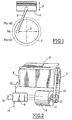
- FIG. 1 diagrammatically shows a piston 1 of an internal combustion engine that moves during operation of the engine, in a cylinder of the engine, as represented by the double arrow 2.
- the piston 1 is connected via a connecting rod 3 to a crankshaft 4 rotatably mounted about an axis 5.
- crankshaft 4 was greatly exaggerated to show the angular positions stop crankshaft.
- crankshaft 4 is rotated about its axis 5 by the connecting rod 3 transforming the linear movement of the piston 1 into movement of rotation.
- crankshaft such as the crankshaft 4 of a heat engine
- the crankshaft when the engine stops, systematically stops at an angular position about its axis of rotation, situated in an angular zone extending from on both sides of an average position P m with a respective angular amplitude A 1 and A 2 .
- FIG. 1 shows, on a dotted circle centered on the axis 5 of the crankshaft 4, the average stopping position P m and the extreme stopping positions P m + A 1 and P m - A 2 .
- the starting power required is about 30% higher than the power corresponding to the initial average position P m .
- the invention thus relates to a method and a device for place the moving parts of the engine and in particular the crankshaft, so automatic, in a position facilitating the starting of the engine and allowing a start with a minimum starting power.
- FIG. 2 schematically shows a device to implement the method of the invention, to facilitate the starting a heat engine 6 represented, in a conventional manner, in the form of a parallelepiped.
- the heat engine 6 has a crankshaft rotatably mounted next a longitudinal axis of the motor 6 and integral, at its longitudinal ends, a pulley 7 and a steering wheel 8, respectively.
- the device for adjusting the stopping position of the motor according to the invention has a rotating electrical machine 10 which can be, as it will be explained later, an alternator or an electric motor.
- the electric rotary machine 10 is connected, via a electronic control module 9, to a battery 14 which can be the battery of a motor vehicle driven by the engine 6.
- a position sensor 15 makes it possible to locate very precisely the angular position of the flywheel 8 and the crankshaft of the engine 6.
- the position sensor 15 is connected to the electronic control module 9, so as to transmit a position signal representative of the instantaneous position of the crankshaft of the heat engine 6.
- the electronic control module 9 also receives a reference signal 16 corresponding to a position signal representative of the ideal average position P m of the crankshaft of the heat engine 6, for which starting is obtained with a minimum starting power.
- the angular position adjustment of the crankshaft of the engine is carried out, during engine shutdown, to obtain a favorable restart position engine after shutdown.
- the electronic control unit 9 When the engine stop is requested by the driver (function stop), an order is transmitted to the electronic control unit 9, way that it realizes the acquisition of an angular position signal of the crankshaft of the heat engine 6 transmitted by the position sensor 15.
- the housing electronic control 9 realizes the continuous acquisition of the position angular angle of the crankshaft of the heat engine 6. It can be realized also the acquisition of the rotational speed of the crankshaft, in time real, while the engine is decelerating.
- the rotating electrical machine 10 which can be constituted by the alternator of the motor vehicle, is made and ordered in such a way as to to be able to work in a reversible way.
- the reversible electric machine 10 can control the deceleration of the engine to force its stop on the preferred angular position P m of the crankshaft of the heat engine 6.
- the electric machine is driven by the housing of electronic control 9, so as to create a resistant torque for braking the engine 6.
- the current produced by the reversible electric machine 10 then recharges the battery 14.
- the control of the electric machine 10 is adapted to hold account, at all operating speeds of the engine, the value of the torque produced, so as to ensure a correct approach to the ideal stop position of the crankshaft.
- FIG. 3 shows, in the form of a logic diagram, the implementation of the method according to the invention.
- the electronic control unit of the electric machine constituted for example by a reversible type alternator receives as input a position signal of the engine crankshaft ⁇ mot.
- the position signal is processed in a first unit 17 of the control module, so as to obtain the engine speed expressed in revolutions / minute in the form of the value N and compared, as shown in 18a, 18b and 18c in the figure 3, at the engine speed at idle N r and at a predetermined speed N 1 lower than the idle speed N r .
- the engine 6 When the speed of the engine N is lower than the speed N 1 , before stopping the engine, the engine 6 is periodically braked by the alternator, as shown in 19b.
- the periodic braking consists of braking the engine 6, when the crankshaft is between the two extreme positions P m + A 1 and P m - A 2 , that is to say in the angular zone of stop crankshaft.
- the resistive torque exerted on the heat engine is modulated from the alternator 10 so as to increase the resistance torque when approaching the ideal position P m of the crankshaft.
- step 18c When the complete stopping of the engine has been obtained, as represented at 18c, a comparison is made between the position of the crankshaft measured by the position sensor 15 and the ideal theoretical position P m . If a difference between these two positions is detected, a static registration is performed as illustrated in step 19c in FIG. 3.
- the static registration of the crankshaft consists in feeding the alternator operating as a motor, in order to turn it in a direction or in the other until the ideal position of the crankshaft.
- the alternator can then be used as a motor to start the engine of the engine with a reduced starting power.
- the function of the reversible alternator realizing, at the moment of the shutdown of the engine, its positioning in the ideal angular position and the starting the engine from this ideal position can facilitate the implementation a "stop and start” function.
- the method according to the invention therefore makes it possible to place the moving parts of the engine at the time of shutdown or after engine shutdown thermal, to obtain ideal starting conditions when using future engine.
- the implementation of the method of the invention also makes it possible to obtain energy saving, because we recover charge energy of the battery, during the braking of the engine, when it stops. In in addition, obtaining the ideal position of stopping the engine is obtained more quickly than when making a subsequent registration after stopping the engine.
- the implementation of the method of the invention is relatively complex and requires the use of calculation and control quite a lot of complexity.
- An electric machine of any type can be used continuous or alternative.
- the invention applies to any heat engine and in particular to thermal engines for traction of motor vehicles.
Landscapes
- Engineering & Computer Science (AREA)
- Chemical & Material Sciences (AREA)
- Combustion & Propulsion (AREA)
- Mechanical Engineering (AREA)
- General Engineering & Computer Science (AREA)
- Output Control And Ontrol Of Special Type Engine (AREA)
- Control Of Vehicle Engines Or Engines For Specific Uses (AREA)
- Electrical Control Of Ignition Timing (AREA)
- Jigs For Machine Tools (AREA)
- Control Of Throttle Valves Provided In The Intake System Or In The Exhaust System (AREA)
- Combined Controls Of Internal Combustion Engines (AREA)
Description
Claims (9)
- Procédé de positionnement des organes mobiles (2, 3, 4) d'un moteur thermique (6), dans une position d'arrêt du moteur (6) facilitant le démarrage, le moteur (6) comportant au moins un piston (2) mobile de manière alternative dans un cylindre, relié à un vilebrequin (4) par une bielle (3) entraínant le vilebrequin (4) en rotation autour d'un axe (5), dans lequel on règle la position angulaire du vilebrequin (4) autour de son axe de rotation (5), pour le placer dans une position angulaire (Pm) prédéterminée, à l'aide d'une machine tournante électrique (10) reliée en rotation au vilebrequin (4), caractérisé par le fait qu'on freine le moteur thermique (6) à l'aide de la machine tournante électrique (10), pendant l'arrêt du moteur thermique (6), de manière qu'au moment de l'arrêt complet du moteur thermique (6), le vilebrequin (4) se trouve dans sa position angulaire (Pm) prédéterminée.
- Procédé selon la revendication 1, caractérisé par le fait qu'on module le freinage du moteur thermique (6) en fonction de la vitesse de rotation du moteur thermique (6) mesurée pendant l'arrêt du moteur thermique (6).
- Procédé suivant la revendication 2, caractérisé par le fait qu'on réalise un freinage continu du moteur thermique (6) en exerçant un couple résistant sur le vilebrequin (4) lorsque la vitesse du moteur thermique (6) est comprise entre une vitesse prédéterminée (N1) inférieure à la vitesse de ralenti (Nr) du moteur et la vitesse de ralenti, et qu'on réalise un freinage périodique du moteur, lorsque sa vitesse est inférieure à la vitesse (N1) prédéterminée inférieure à la vitesse de ralenti, le freinage du moteur étant réalisé au cours de périodes où le vilebrequin est dans une zone d'arrêt s'étendant de part et d'autre de la position angulaire prédéterminée (Pm).
- Procédé suivant la revendication 3, caractérisé par le fait qu'on module le freinage périodique du moteur dans la zone angulaire d'arrêt du vilebrequin (4) en rendant le couple résistant de la machine électrique (10) maximal dans la position angulaire prédéterminée (Pm) du vilebrequin (4).
- Procédé suivant l'une quelconque des revendications 1 à 4, caractérisé par le fait qu'après l'arrêt complet du moteur thermique (6), on effectue un recalage statique de position du vilebrequin (4), en utilisant la machine tournante électrique comme moteur.
- Procédé suivant l'une quelconque des revendications 1 à 5, caractérisé par le fait qu'on mesure la position angulaire du vilebrequin (4) du moteur, qu'on compare cette position angulaire à la position angulaire prédéterminée (Pm) et qu'on élabore à partir du résultat de la comparaison, un signal de commande de la machine tournante électrique (10) pour réaliser l'une au moins des fonctions de freinage et de recalage du moteur thermique (6).
- Dispositif de positionnement des organes mobiles (2, 3, 4) d'un moteur thermique (6), dans une position d'arrêt du moteur (6) facilitant le démarrage, le moteur thermique (6) comportant au moins un piston (2) mobile de manière alternative dans un cylindre, relié à un vilebrequin (4) par une bielle (3) entraínant le vilebrequin en rotation autour d'un axe (5), caractérisé par le fait qu'il comporte une machine électrique tournante (10) reliée en rotation au vilebrequin (4) du moteur thermique (6) et des moyens de commande électronique (9, 23) de la machine électrique (10) pour freiner et arrêter le moteur thermique (6) avec son vilebrequin dans une position angulaire prédéterminée (Pm).
- Dispositif suivant la revendication 7, caractérisé par le fait que la machine tournante électrique (10) est un alternateur réversible pouvant fonctionner en alternateur ou en moteur.
- Dispositif suivant l'une quelconque des revendications 7 et 8, caractérisé par le fait que les moyens de commande de la machine tournante électrique (10) comportent des moyens de comparaison de la vitesse du moteur à des valeurs prédéterminées et des moyens de commande du freinage du moteur thermique (6) par la machine tournante électrique (10) en fonction des résultats de la comparaison de la vitesse du moteur et des valeurs prédéterminées.
Applications Claiming Priority (2)
| Application Number | Priority Date | Filing Date | Title |
|---|---|---|---|
| FR0003609 | 2000-03-21 | ||
| FR0003609A FR2806757B1 (fr) | 2000-03-21 | 2000-03-21 | Procede et dispositif de positionnement d'un moteur thermique, dans une position d'arret facilitant le demarrage |
Publications (2)
| Publication Number | Publication Date |
|---|---|
| EP1136696A1 EP1136696A1 (fr) | 2001-09-26 |
| EP1136696B1 true EP1136696B1 (fr) | 2005-08-03 |
Family
ID=8848344
Family Applications (1)
| Application Number | Title | Priority Date | Filing Date |
|---|---|---|---|
| EP01400722A Expired - Lifetime EP1136696B1 (fr) | 2000-03-21 | 2001-03-20 | Procédé et dispositif de positionnement d'un moteur thermique, dans une position d'arrêt facilitant le démarrage |
Country Status (5)
| Country | Link |
|---|---|
| EP (1) | EP1136696B1 (fr) |
| AT (1) | ATE301246T1 (fr) |
| DE (1) | DE60112349T2 (fr) |
| ES (1) | ES2245673T3 (fr) |
| FR (1) | FR2806757B1 (fr) |
Cited By (1)
| Publication number | Priority date | Publication date | Assignee | Title |
|---|---|---|---|---|
| WO2015111275A1 (fr) * | 2014-01-21 | 2015-07-30 | Toyota Jidosha Kabushiki Kaisha | Appareil de commande pour alternateur de véhicule |
Families Citing this family (13)
| Publication number | Priority date | Publication date | Assignee | Title |
|---|---|---|---|---|
| DE10050170A1 (de) * | 2000-10-11 | 2002-04-25 | Daimler Chrysler Ag | Vorrichtung zum Starten einer Brennkraftmaschine |
| JP2004036429A (ja) * | 2002-07-01 | 2004-02-05 | Toyota Motor Corp | 内燃機関の制御装置 |
| JP4082578B2 (ja) * | 2002-10-04 | 2008-04-30 | 本田技研工業株式会社 | エンジン始動制御装置 |
| EP1422421B1 (fr) * | 2002-11-25 | 2010-11-24 | Ford Global Technologies, LLC | Méthode et dispositif d'arrêt et de redémarrage d'un moteur à combustion interne |
| DE60232524D1 (de) * | 2002-11-25 | 2009-07-16 | Ford Global Tech Llc | Blockierungsmechanismus für die Kurbelwelle einer Brennkraftmaschine |
| EP1588047B1 (fr) | 2003-01-27 | 2008-04-02 | Toyota Jidosha Kabushiki Kaisha | Appareil de commande d'un moteur a combustion interne |
| JP3794389B2 (ja) * | 2003-01-27 | 2006-07-05 | トヨタ自動車株式会社 | 内燃機関の停止制御装置 |
| JP4062264B2 (ja) | 2003-06-06 | 2008-03-19 | アイシン・エィ・ダブリュ株式会社 | 車両駆動制御装置、車両駆動制御方法及びプログラム |
| JP4075699B2 (ja) | 2003-06-20 | 2008-04-16 | トヨタ自動車株式会社 | 車両の制御装置 |
| EP1586765B1 (fr) | 2004-04-15 | 2011-06-29 | TEMIC Automotive Electric Motors GmbH | Procédé et système de commande pour positioner les vilebrequine lors de l'arrêt d'un moteur à combustion |
| FR2970128A1 (fr) * | 2011-01-04 | 2012-07-06 | Peugeot Citroen Automobiles Sa | Procede de freinage d'un moteur thermique et vehicule |
| EP3064762B1 (fr) * | 2013-12-20 | 2021-07-07 | Yamaha Hatsudoki Kabushiki Kaisha | Véhicule à enfourcher avec ensemble moteur |
| FR3110638A1 (fr) | 2020-05-25 | 2021-11-26 | Psa Automobiles Sa | Procede de repositionnement d'un vilebrequin de moteur thermique avant re-demarrage |
Family Cites Families (3)
| Publication number | Priority date | Publication date | Assignee | Title |
|---|---|---|---|---|
| US3762387A (en) * | 1969-08-29 | 1973-10-02 | Husqvarna Vapenfabriks Ab | Arrangement for automatically positioning a piston in an internal combustion engine |
| DE4439849A1 (de) * | 1994-11-08 | 1996-05-09 | Bosch Gmbh Robert | Verfahren und Vorrichtung zum Starten einer Brennkraftmaschine |
| DE19841752A1 (de) * | 1998-09-11 | 2000-03-16 | Bayerische Motoren Werke Ag | Verfahren zum Starten eines Verbrennungsmotors |
-
2000
- 2000-03-21 FR FR0003609A patent/FR2806757B1/fr not_active Expired - Fee Related
-
2001
- 2001-03-20 ES ES01400722T patent/ES2245673T3/es not_active Expired - Lifetime
- 2001-03-20 EP EP01400722A patent/EP1136696B1/fr not_active Expired - Lifetime
- 2001-03-20 DE DE60112349T patent/DE60112349T2/de not_active Expired - Lifetime
- 2001-03-20 AT AT01400722T patent/ATE301246T1/de not_active IP Right Cessation
Cited By (1)
| Publication number | Priority date | Publication date | Assignee | Title |
|---|---|---|---|---|
| WO2015111275A1 (fr) * | 2014-01-21 | 2015-07-30 | Toyota Jidosha Kabushiki Kaisha | Appareil de commande pour alternateur de véhicule |
Also Published As
| Publication number | Publication date |
|---|---|
| FR2806757B1 (fr) | 2002-06-21 |
| DE60112349D1 (de) | 2005-09-08 |
| EP1136696A1 (fr) | 2001-09-26 |
| ATE301246T1 (de) | 2005-08-15 |
| ES2245673T3 (es) | 2006-01-16 |
| FR2806757A1 (fr) | 2001-09-28 |
| DE60112349T2 (de) | 2006-03-09 |
Similar Documents
| Publication | Publication Date | Title |
|---|---|---|
| EP2512898B1 (fr) | Procede et systeme de desaccouplement d'une machine electrique sur un train roulant de vehicule, notamment d'un vehicule automobile hydride | |
| EP1136696A1 (fr) | Procédé et dispositif de positionnement d'un moteur thermique, dans une position d'arrêt facilitant le démarrage | |
| FR2636108A1 (fr) | Dispositif pour regler la position angulaire relative de deux arbres relies selon une liaison motrice | |
| EP1567766B1 (fr) | Systeme de transmission associant un moteur a combustion interne et un alterno-demarreur | |
| EP2160510A1 (fr) | Dispositif de demarrage d'un moteur thermique, notamment de vehicule automobile | |
| FR2818315A1 (fr) | Procede et dispositif de commande pour determiner l'angle vilebrequin d'un moteur a combustion interne, et train d'entrainement | |
| WO2011138367A1 (fr) | Circuit et procédé de commande pour moteur électrique, notamment d'entraînement d'essuie-glace | |
| FR3049540A1 (fr) | Appareil de commande de vehicule et procede de commande de vehicule | |
| FR2815087A1 (fr) | Dispositif pour demarrer un moteur a combustion interne | |
| WO1981000833A1 (fr) | Groupe propulseur pour vehicule automobile utilisant un moteur thermique jusqu'aux plus bas regimes | |
| EP2441949B1 (fr) | Procédé de détection d'un glissement d'une courroie d'accessoires | |
| FR2824599A1 (fr) | Dispositif de demarrage d'un moteur a combustion interne de propulsion d'un vehicule automobile | |
| FR2486610A1 (fr) | Dispositif d'entrainement rotatif a deux vitesses, notamment pour alternateur de vehicule automobile | |
| EP0069017A1 (fr) | Installation de découpe rotative de flans | |
| FR2846380A1 (fr) | Ensemble a demarreur/alternateur pour moteur a combustion interne et procede pour sa commande | |
| FR2514424A1 (fr) | Vehicule automobile ayant un demarreur lie au moteur par une roue libre | |
| FR3062883B1 (fr) | Systeme et procede de repositionnement de rotor de moteur thermique | |
| EP0767367A1 (fr) | Procédé et dispositif d'équilibrage d'un corps tournant en rotation par addition de masses d'équilibrage | |
| FR2935307A1 (fr) | Vehicule hybride muni d'au moins une machine electrique accouplee aux roues par l'intermediaire d'un reducteur a rapport de demultiplication variable. | |
| FR2847300A1 (fr) | Reglage d'arbre a cames | |
| EP1258616B1 (fr) | Dispositif et procédé de freinage et d'arrêt d'un moteur à combustion interne de propulsion d'un véhicule automobile | |
| FR3013915A1 (fr) | Procede de pilotage d'une machine electrique pour assurer le redemarrage d'un vehicule automobile | |
| FR2984957A1 (fr) | Groupe moteur | |
| FR2797909A1 (fr) | Procede pour commander le fonctionnement d'unites auxiliaires d'un moteur a combustion interne et dispositif d'entrainement pour de telles unites | |
| WO2021255351A1 (fr) | Procede de reduction de contraintes sur un tendeur accessoires |
Legal Events
| Date | Code | Title | Description |
|---|---|---|---|
| PUAI | Public reference made under article 153(3) epc to a published international application that has entered the european phase |
Free format text: ORIGINAL CODE: 0009012 |
|
| AK | Designated contracting states |
Kind code of ref document: A1 Designated state(s): AT BE CH CY DE DK ES FI FR GB GR IE IT LI LU MC NL PT SE TR |
|
| AX | Request for extension of the european patent |
Free format text: AL;LT;LV;MK;RO;SI |
|
| 17P | Request for examination filed |
Effective date: 20020301 |
|
| AKX | Designation fees paid |
Free format text: AT BE CH CY DE DK ES FI FR GB GR IE IT LI LU MC NL PT SE TR |
|
| 17Q | First examination report despatched |
Effective date: 20040820 |
|
| GRAP | Despatch of communication of intention to grant a patent |
Free format text: ORIGINAL CODE: EPIDOSNIGR1 |
|
| GRAS | Grant fee paid |
Free format text: ORIGINAL CODE: EPIDOSNIGR3 |
|
| GRAA | (expected) grant |
Free format text: ORIGINAL CODE: 0009210 |
|
| AK | Designated contracting states |
Kind code of ref document: B1 Designated state(s): AT BE CH CY DE DK ES FI FR GB GR IE IT LI LU MC NL PT SE TR |
|
| PG25 | Lapsed in a contracting state [announced via postgrant information from national office to epo] |
Ref country code: TR Free format text: LAPSE BECAUSE OF FAILURE TO SUBMIT A TRANSLATION OF THE DESCRIPTION OR TO PAY THE FEE WITHIN THE PRESCRIBED TIME-LIMIT Effective date: 20050803 Ref country code: IE Free format text: LAPSE BECAUSE OF FAILURE TO SUBMIT A TRANSLATION OF THE DESCRIPTION OR TO PAY THE FEE WITHIN THE PRESCRIBED TIME-LIMIT Effective date: 20050803 Ref country code: NL Free format text: LAPSE BECAUSE OF FAILURE TO SUBMIT A TRANSLATION OF THE DESCRIPTION OR TO PAY THE FEE WITHIN THE PRESCRIBED TIME-LIMIT Effective date: 20050803 Ref country code: AT Free format text: LAPSE BECAUSE OF FAILURE TO SUBMIT A TRANSLATION OF THE DESCRIPTION OR TO PAY THE FEE WITHIN THE PRESCRIBED TIME-LIMIT Effective date: 20050803 Ref country code: FI Free format text: LAPSE BECAUSE OF FAILURE TO SUBMIT A TRANSLATION OF THE DESCRIPTION OR TO PAY THE FEE WITHIN THE PRESCRIBED TIME-LIMIT Effective date: 20050803 |
|
| REG | Reference to a national code |
Ref country code: GB Ref legal event code: FG4D Free format text: NOT ENGLISH |
|
| REG | Reference to a national code |
Ref country code: CH Ref legal event code: EP |
|
| REG | Reference to a national code |
Ref country code: IE Ref legal event code: FG4D Free format text: LANGUAGE OF EP DOCUMENT: FRENCH |
|
| REF | Corresponds to: |
Ref document number: 60112349 Country of ref document: DE Date of ref document: 20050908 Kind code of ref document: P |
|
| GBT | Gb: translation of ep patent filed (gb section 77(6)(a)/1977) |
Effective date: 20050912 |
|
| PG25 | Lapsed in a contracting state [announced via postgrant information from national office to epo] |
Ref country code: DK Free format text: LAPSE BECAUSE OF FAILURE TO SUBMIT A TRANSLATION OF THE DESCRIPTION OR TO PAY THE FEE WITHIN THE PRESCRIBED TIME-LIMIT Effective date: 20051103 Ref country code: GR Free format text: LAPSE BECAUSE OF FAILURE TO SUBMIT A TRANSLATION OF THE DESCRIPTION OR TO PAY THE FEE WITHIN THE PRESCRIBED TIME-LIMIT Effective date: 20051103 Ref country code: SE Free format text: LAPSE BECAUSE OF FAILURE TO SUBMIT A TRANSLATION OF THE DESCRIPTION OR TO PAY THE FEE WITHIN THE PRESCRIBED TIME-LIMIT Effective date: 20051103 |
|
| PG25 | Lapsed in a contracting state [announced via postgrant information from national office to epo] |
Ref country code: PT Free format text: LAPSE BECAUSE OF FAILURE TO SUBMIT A TRANSLATION OF THE DESCRIPTION OR TO PAY THE FEE WITHIN THE PRESCRIBED TIME-LIMIT Effective date: 20060103 |
|
| REG | Reference to a national code |
Ref country code: ES Ref legal event code: FG2A Ref document number: 2245673 Country of ref document: ES Kind code of ref document: T3 |
|
| NLV1 | Nl: lapsed or annulled due to failure to fulfill the requirements of art. 29p and 29m of the patents act | ||
| REG | Reference to a national code |
Ref country code: IE Ref legal event code: FD4D |
|
| PG25 | Lapsed in a contracting state [announced via postgrant information from national office to epo] |
Ref country code: BE Free format text: LAPSE BECAUSE OF NON-PAYMENT OF DUE FEES Effective date: 20060331 Ref country code: MC Free format text: LAPSE BECAUSE OF NON-PAYMENT OF DUE FEES Effective date: 20060331 Ref country code: LI Free format text: LAPSE BECAUSE OF NON-PAYMENT OF DUE FEES Effective date: 20060331 Ref country code: CH Free format text: LAPSE BECAUSE OF NON-PAYMENT OF DUE FEES Effective date: 20060331 Ref country code: LU Free format text: LAPSE BECAUSE OF NON-PAYMENT OF DUE FEES Effective date: 20060331 |
|
| PLBE | No opposition filed within time limit |
Free format text: ORIGINAL CODE: 0009261 |
|
| STAA | Information on the status of an ep patent application or granted ep patent |
Free format text: STATUS: NO OPPOSITION FILED WITHIN TIME LIMIT |
|
| 26N | No opposition filed |
Effective date: 20060504 |
|
| REG | Reference to a national code |
Ref country code: CH Ref legal event code: PL |
|
| REG | Reference to a national code |
Ref country code: GB Ref legal event code: 746 Effective date: 20070116 |
|
| BERE | Be: lapsed |
Owner name: PEUGEOT CITROEN AUTOMOBILES SA Effective date: 20060331 |
|
| PG25 | Lapsed in a contracting state [announced via postgrant information from national office to epo] |
Ref country code: CY Free format text: LAPSE BECAUSE OF FAILURE TO SUBMIT A TRANSLATION OF THE DESCRIPTION OR TO PAY THE FEE WITHIN THE PRESCRIBED TIME-LIMIT Effective date: 20050803 |
|
| PGFP | Annual fee paid to national office [announced via postgrant information from national office to epo] |
Ref country code: ES Payment date: 20090305 Year of fee payment: 9 |
|
| REG | Reference to a national code |
Ref country code: ES Ref legal event code: FD2A Effective date: 20110415 |
|
| PG25 | Lapsed in a contracting state [announced via postgrant information from national office to epo] |
Ref country code: ES Free format text: LAPSE BECAUSE OF NON-PAYMENT OF DUE FEES Effective date: 20110404 |
|
| PG25 | Lapsed in a contracting state [announced via postgrant information from national office to epo] |
Ref country code: ES Free format text: LAPSE BECAUSE OF NON-PAYMENT OF DUE FEES Effective date: 20100321 |
|
| PGFP | Annual fee paid to national office [announced via postgrant information from national office to epo] |
Ref country code: IT Payment date: 20120225 Year of fee payment: 12 |
|
| PGFP | Annual fee paid to national office [announced via postgrant information from national office to epo] |
Ref country code: GB Payment date: 20130228 Year of fee payment: 13 |
|
| GBPC | Gb: european patent ceased through non-payment of renewal fee |
Effective date: 20140320 |
|
| PG25 | Lapsed in a contracting state [announced via postgrant information from national office to epo] |
Ref country code: GB Free format text: LAPSE BECAUSE OF NON-PAYMENT OF DUE FEES Effective date: 20140320 |
|
| PG25 | Lapsed in a contracting state [announced via postgrant information from national office to epo] |
Ref country code: IT Free format text: LAPSE BECAUSE OF NON-PAYMENT OF DUE FEES Effective date: 20140320 |
|
| REG | Reference to a national code |
Ref country code: FR Ref legal event code: PLFP Year of fee payment: 16 |
|
| REG | Reference to a national code |
Ref country code: FR Ref legal event code: PLFP Year of fee payment: 17 |
|
| REG | Reference to a national code |
Ref country code: FR Ref legal event code: PLFP Year of fee payment: 18 |
|
| REG | Reference to a national code |
Ref country code: FR Ref legal event code: CA Effective date: 20180312 Ref country code: FR Ref legal event code: CD Owner name: PEUGEOT CITROEN AUTOMOBILES SA, FR Effective date: 20180312 |
|
| PGFP | Annual fee paid to national office [announced via postgrant information from national office to epo] |
Ref country code: DE Payment date: 20190219 Year of fee payment: 19 |
|
| PGFP | Annual fee paid to national office [announced via postgrant information from national office to epo] |
Ref country code: FR Payment date: 20190220 Year of fee payment: 19 |
|
| REG | Reference to a national code |
Ref country code: DE Ref legal event code: R119 Ref document number: 60112349 Country of ref document: DE |
|
| PG25 | Lapsed in a contracting state [announced via postgrant information from national office to epo] |
Ref country code: DE Free format text: LAPSE BECAUSE OF NON-PAYMENT OF DUE FEES Effective date: 20201001 Ref country code: FR Free format text: LAPSE BECAUSE OF NON-PAYMENT OF DUE FEES Effective date: 20200331 |